Download to read offline
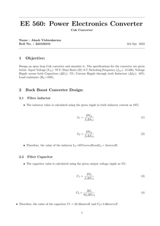
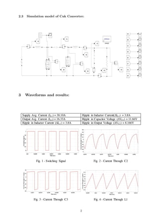

The document describes the design and simulation of an open loop Cuk converter. The specifications include an input voltage of 70V, duty ratio of 0.7, switching frequency of 15kHz, voltage ripple of 5% across capacitors, and current ripple of 10% through inductors. The inductor values are calculated as 857uH and 2uH using the current ripple specification. The capacitor values are calculated as 65.32uF and 1.66uF using the voltage ripple specification. A simulation model of the Cuk converter is created based on the design values.


![ppt on IC [Integrated Circuit]](https://cdn.slidesharecdn.com/ss_thumbnails/1-171227170055-thumbnail.jpg?width=640&height=640&fit=bounds)


