Downloaded 184 times
![REFERENCES
[1] Tanwani, N. K., Memon, A. P., Adil, W. A., & Ansari, J. A. Simulation Techniques of
Electrical Power System Stability Studies Utilizing Matlab/Simulink. engineer, 9, 18.
[2] Yarlagadda, Venu, BV Sankar Ram, and K. R. M. Rao. "Automatic Control of Thyristor
Controlled Series Capacitor (TCSC)." margin 2.3 (2012): 444-449.
[3] Narne, Rajendraprasad, P. C. Panda, and Jose P. Therattil. "Transient stability
enhancement of SMIB system using PSS and TCSC-based controllers." Power Electronics
and Drive Systems (PEDS), 2011 IEEE Ninth International Conference on. IEEE, 2011.
[4] Narain G.Hingorani, Laszlo Gyugyi, 2000, “Concepts and Technology of Flexible AC
Transmission Systems”, Understanding FACTS:IEEE Inc., New York, USA, 0-78033455-8.
[5] R. Mohan Mathur, R.K Verma, “Thyristor Based FACTS Controllers for Electrical
Transmission System “, Wiley & Sons, Inc. Publication, 2002.
[6] Kothari, Dwarkadas Pralhaddas, and I. J. Nagrath. Modern power system analysis. Tata
McGraw-Hill Education, 2003.
24](https://image.slidesharecdn.com/tcsc-170603151126/85/TCSC-24-320.jpg)


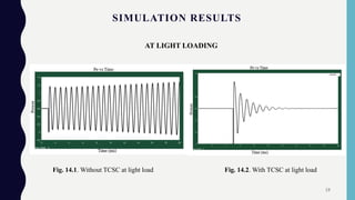
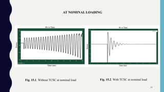
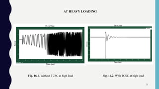
This document discusses using a Thyristor Controlled Series Capacitor (TCSC) to enhance power system stability. It first reviews power system stability concepts like steady state, transient, and dynamic stability. It then discusses factors limiting transmission line loading capacity and introduces Flexible AC Transmission Systems (FACTS) technology. The document focuses on TCSC, explaining its working principle and applications. It presents simulation results in MATLAB showing that TCSC improves stability performance and dampens power oscillations under different loading conditions like light, nominal, and heavy loads. The conclusion is that TCSC effectively enhances power system stability.