Downloaded 290 times

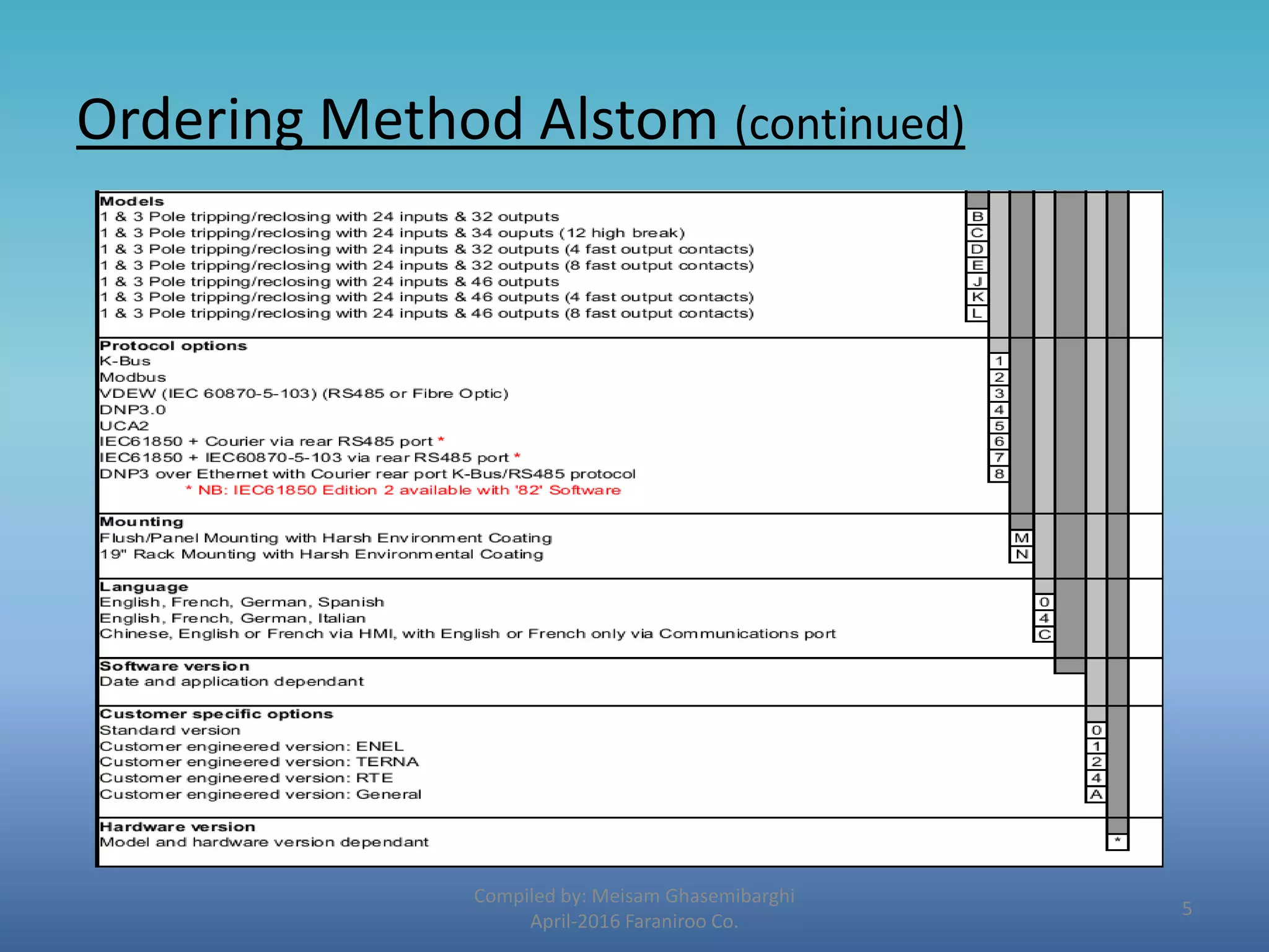


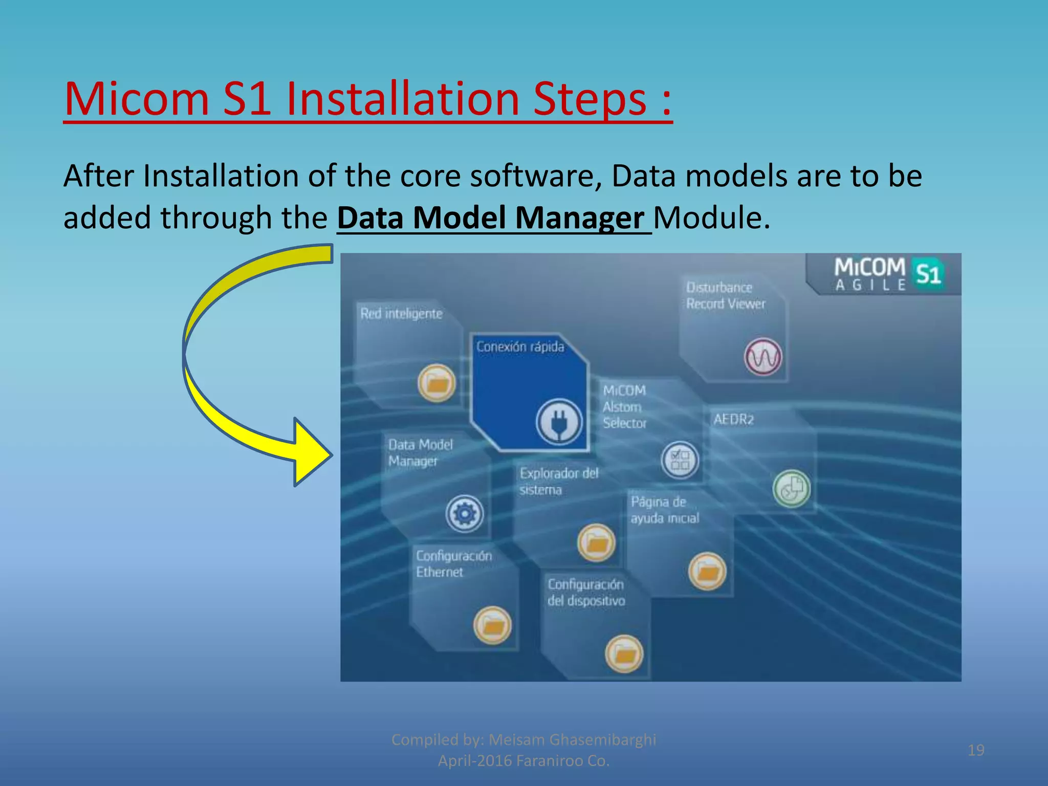


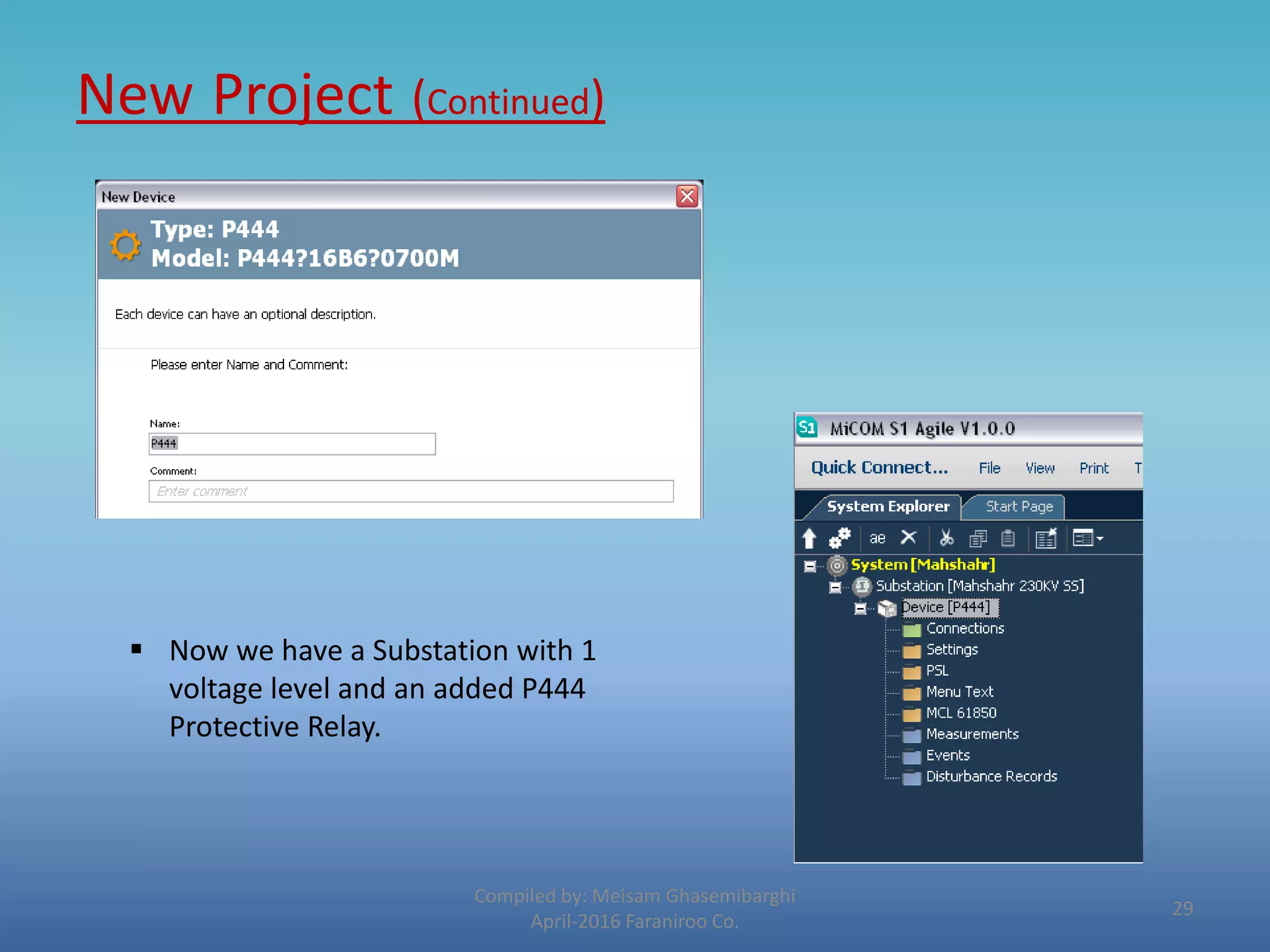

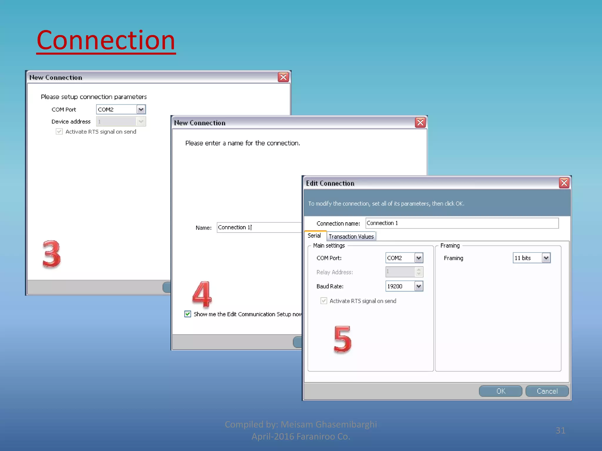

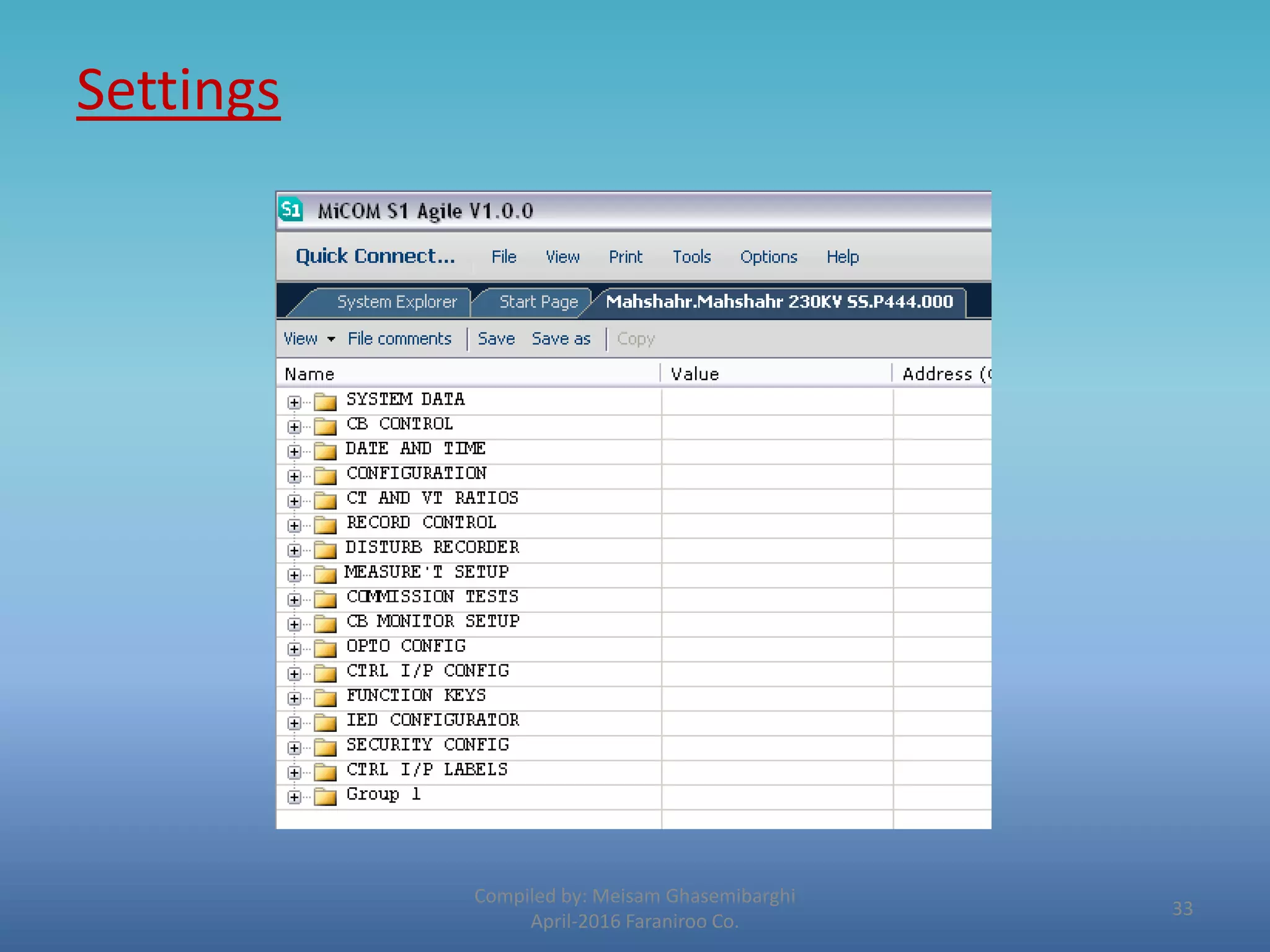
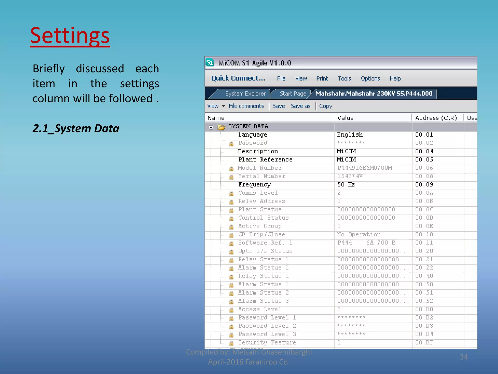


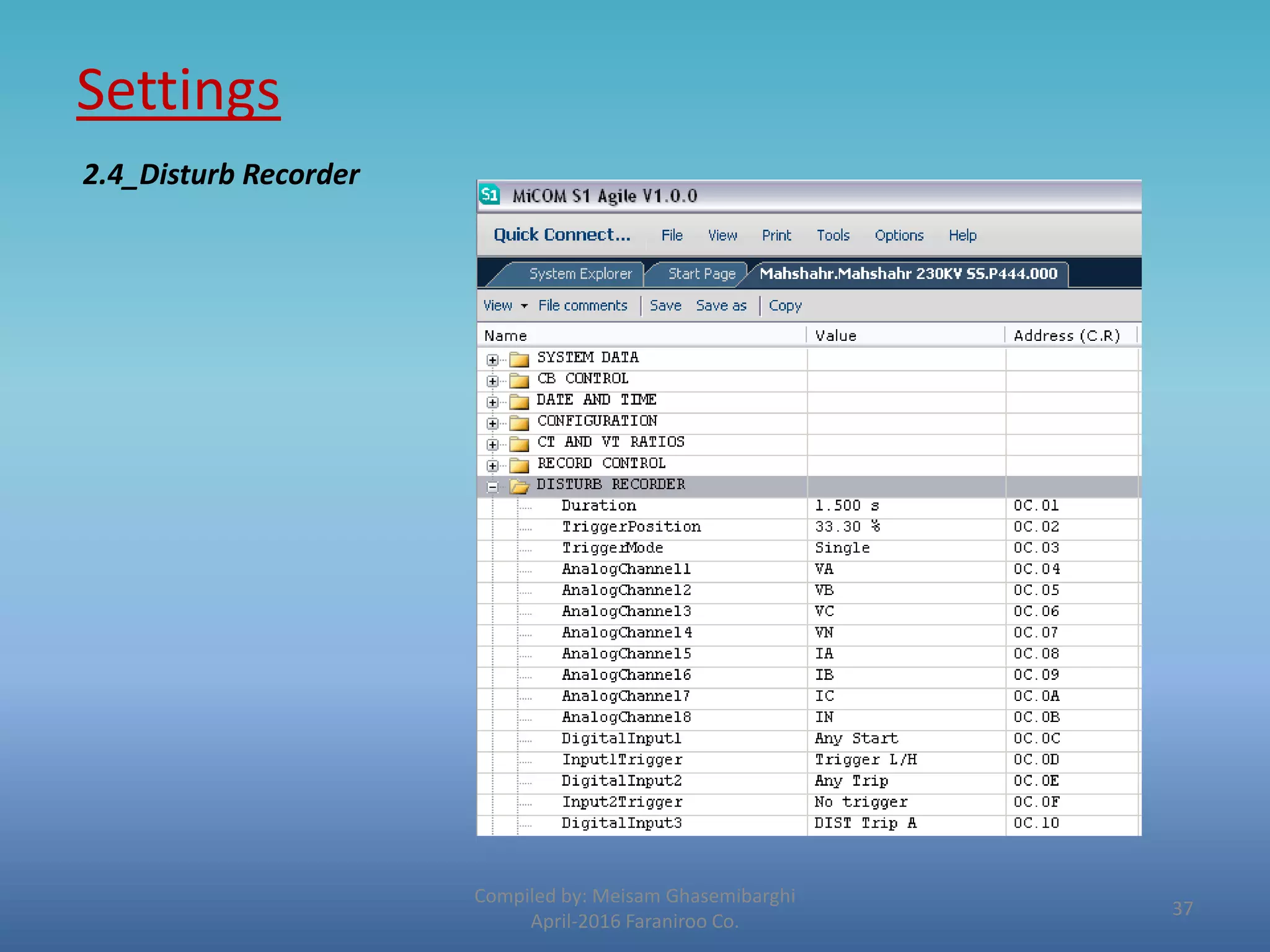


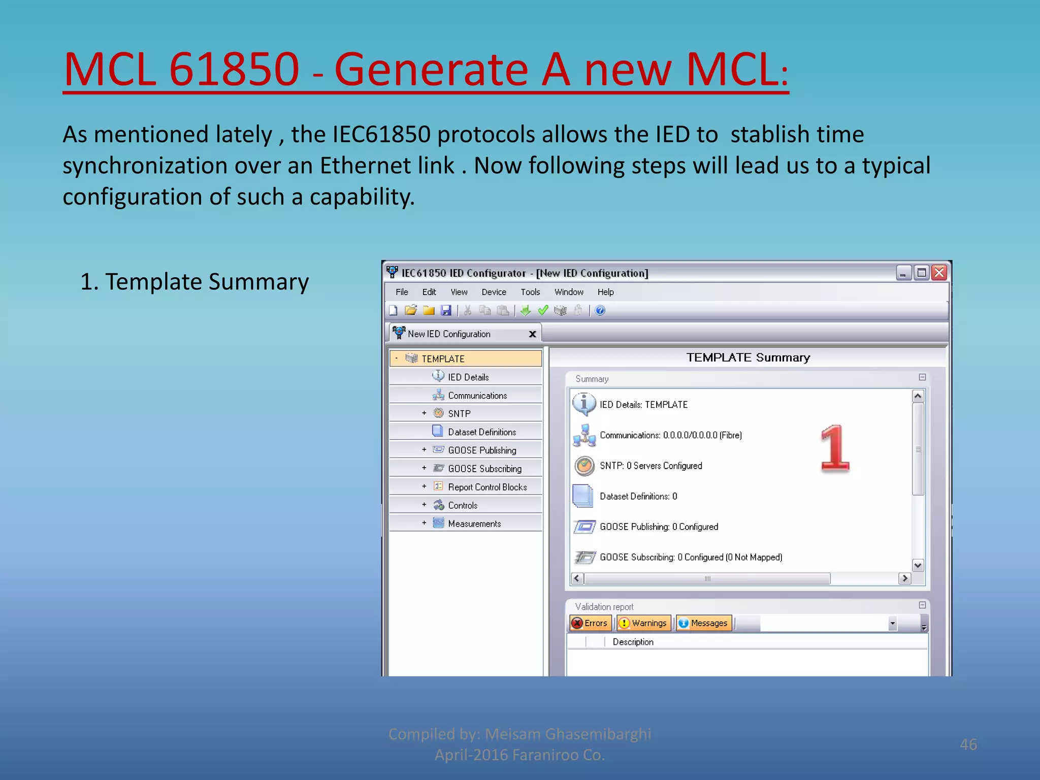


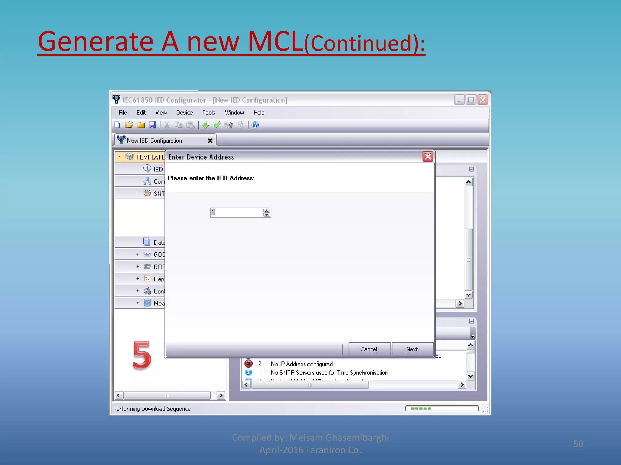
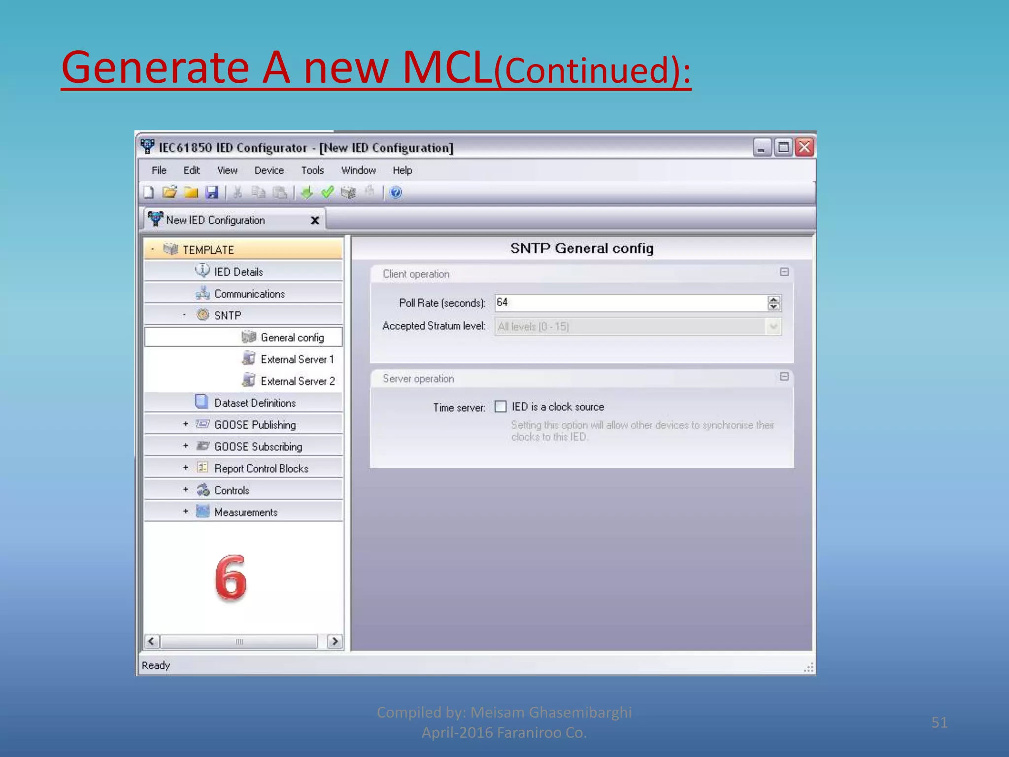
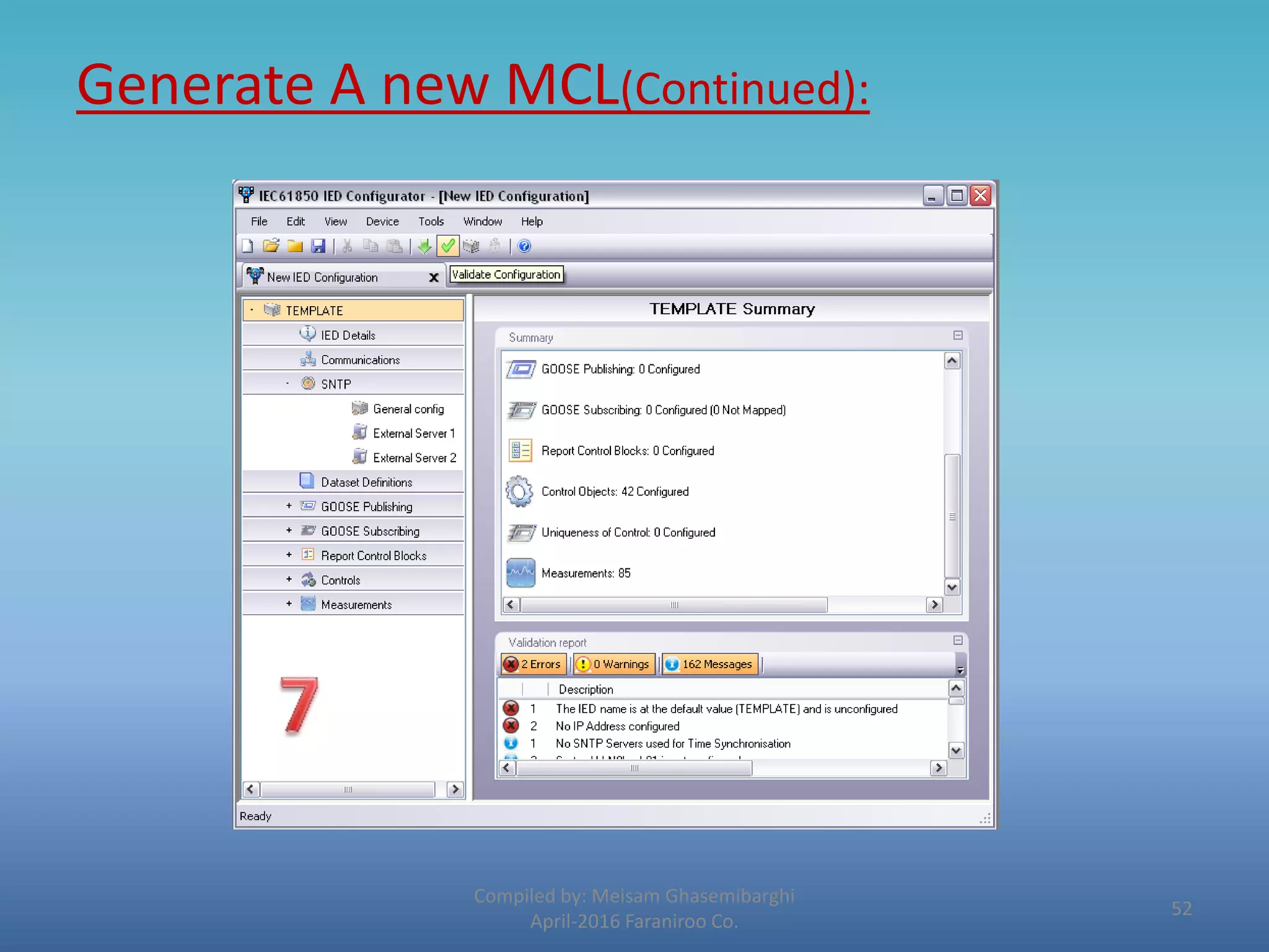


The document provides an introduction to Alstom's Micom protective relays and their Agile software. It discusses the key features of Micom S1 Agile, including its integrated programmable curve tool and redundant Ethernet configuration. It also covers installing data models, creating a new project in S1 Agile, and configuring settings, programmable scheme logic (PSL), and MCL 61850 capabilities. The document is a training compilation on Micom protective relays and their S1 Agile configuration software.


![Rubén Santamarta - SCADA Trojans: Attacking the Grid [Rooted CON 2011]](https://cdn.slidesharecdn.com/ss_thumbnails/scadatrojansrubenrootedcon-110322163433-phpapp02-thumbnail.jpg?width=640&height=640&fit=bounds)