This document discusses relay coordination and overcurrent protection. It begins with an introduction to relay coordination, covering the basic philosophy of selectivity, sensitivity and speed. It then discusses the need for protection coordination to ensure equipment safety, proper discrimination of faulty vs healthy portions of the power system, and reduced outage times. The document outlines various protection schemes including unit and non-unit schemes. It also covers overcurrent protection characteristics such as time-overcurrent, definite time, and instantaneous and provides examples of how relay trip times are calculated based on standards.


![ RC TYPES:
15
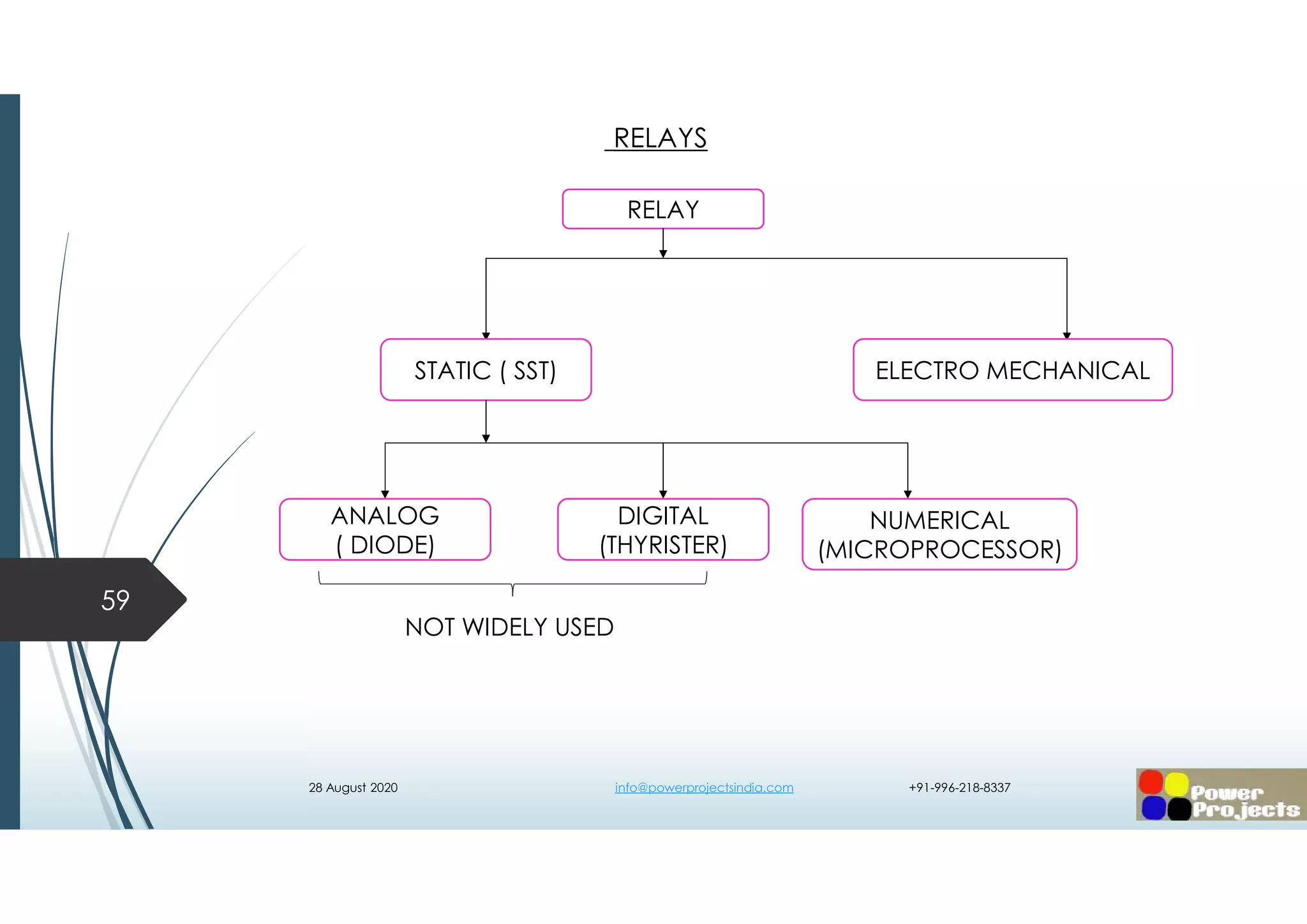
SIGNIFICANCE OF RELAY AND RELEASE
RELAY CO-ORDINATION
>1kV <1kV
MV LV
RELAY
RELEASE
OVER CURRENT OVER CURRENTEARTH FAULT EARTH FAULT
TIME OVER CURRENT(TOC)
OR IDMT [51]
DEFINITE MINI’M TIME(DMT)
OR DEFINITE TIME( DT) ,[50]
INSTANTANEOUS [50 I]
LONG [51]
SHORT [50 ]
INSTANTANEOUS [50 I]
28 August 2020 info@powerprojectsindia.com +91-996-218-8337](https://image.slidesharecdn.com/ipsa-mvrelayco-ordiantionshaikadam-200828023731/75/Ipsa-mv-relay-co-ordiantion-shaik-adam-15-2048.jpg)
![ CHARACTERISTICS :
Depending on the time of operation of relays, they are categorized as follows:
TOC – TIME OVER CURRENT (OR) INVERSE DEFINITE MINIMUM TIME ( IDMT) [51]
Standard / Normal / Moderate Inverse [ IEC/IEEE /ANSI ]
Long Inverse [ IEC/IEEE /ANSI ]
Very Inverse [ IEC/IEEE /ANSI ]
Extreme Inverse [ IEC/IEEE /ANSI ]
DEFINITE MINIMUM TIME OR DEFINITE TIME [50]
INSTANTANEOUS [50I]
20
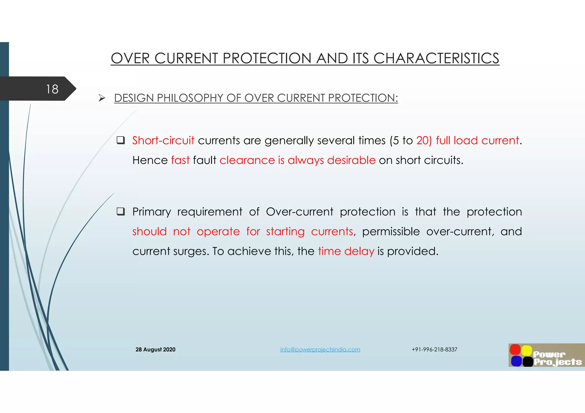
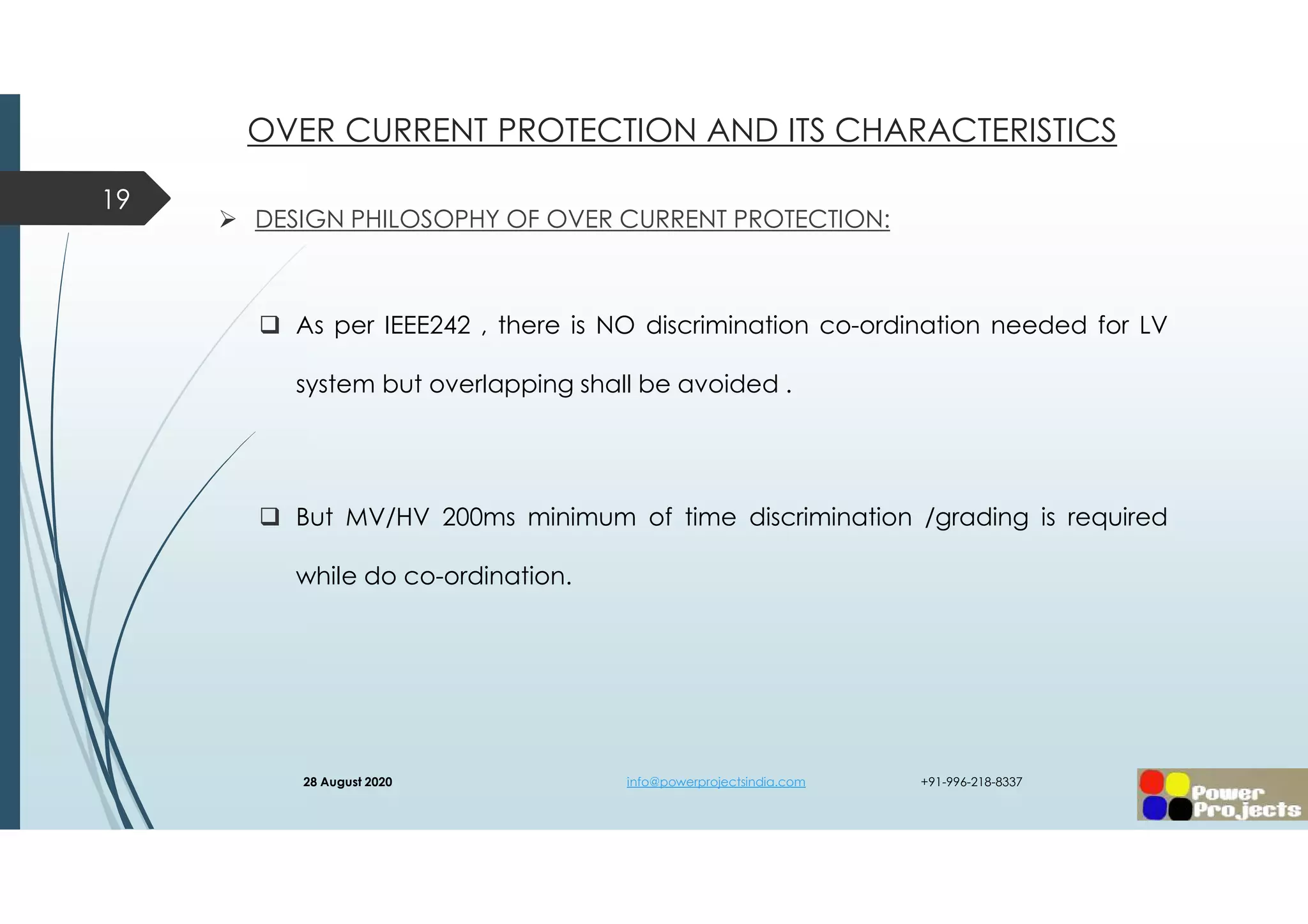
OVER CURRENT PROTECTION AND ITS CHARACTERISTICS
28 August 2020 info@powerprojectsindia.com +91-996-218-8337](https://image.slidesharecdn.com/ipsa-mvrelayco-ordiantionshaikadam-200828023731/75/Ipsa-mv-relay-co-ordiantion-shaik-adam-20-2048.jpg)
![ CHARACTERISTICS :
TOC – TIME OVER CURRENT (OR) INVERSE DEFINITE MINIMUM TIME ( IDMT) [51]
Inverse definite minimum time (IDMT) over-current Relay is one in which the
operating time is approximately inversely proportional to the fault current near
pick-up value and then becomes constant above the pick-up value of the
relay.
The relay will go to a definite time after 20 times of pickup current.
21
OVER CURRENT PROTECTION AND ITS CHARACTERISTICS
28 August 2020 info@powerprojectsindia.com +91-996-218-8337](https://image.slidesharecdn.com/ipsa-mvrelayco-ordiantionshaikadam-200828023731/75/Ipsa-mv-relay-co-ordiantion-shaik-adam-21-2048.jpg)
![TOC – TIME OVER CURRENT (OR) INVERSE DEFINITE MINIMUM TIME ( IDMT) [51]
From the picture, it is clear that there is some definite time after which the Relay
will operate. It is also clear that the time of operation at Pick-up value is nearly
very high and as the fault current increases the time of operation decreases
maintaining some definite time.
22
OVER CURRENT PROTECTION AND ITS CHARACTERISTICS
28 August 2020 info@powerprojectsindia.com +91-996-218-8337](https://image.slidesharecdn.com/ipsa-mvrelayco-ordiantionshaikadam-200828023731/75/Ipsa-mv-relay-co-ordiantion-shaik-adam-22-2048.jpg)
![ CHARECTERISTICS :
DEFINITE MINIMUM TIME OR DEFINITE TIME [50]
This relay is created by applying intentional time delay after crossing pick up
the value of the current. A definite minimum time overcurrent relay can be
adjusted to issue a trip output at an exact amount of time after it picks up.
Thus, it has a time setting adjustment and pickup adjustment.
23
OVER CURRENT PROTECTION AND ITS CHARACTERISTICS
28 August 2020 info@powerprojectsindia.com +91-996-218-8337](https://image.slidesharecdn.com/ipsa-mvrelayco-ordiantionshaikadam-200828023731/75/Ipsa-mv-relay-co-ordiantion-shaik-adam-23-2048.jpg)
![ CHARECTERISTICS :
INSTANTANEOUS [50I]
This relay is referred as instantaneous over current relay, as ideally, the relay
operates as soon as the current gets higher than pick upsetting current. There
is no intentional time delay applied. But there is always an inherent time delay
which we cannot avoid practically. In practice, the operating time of an
instantaneous relay is of the order of a few milliseconds..
24
OVER CURRENT PROTECTION AND ITS CHARACTERISTICS
28 August 2020 info@powerprojectsindia.com +91-996-218-8337](https://image.slidesharecdn.com/ipsa-mvrelayco-ordiantionshaikadam-200828023731/75/Ipsa-mv-relay-co-ordiantion-shaik-adam-24-2048.jpg)


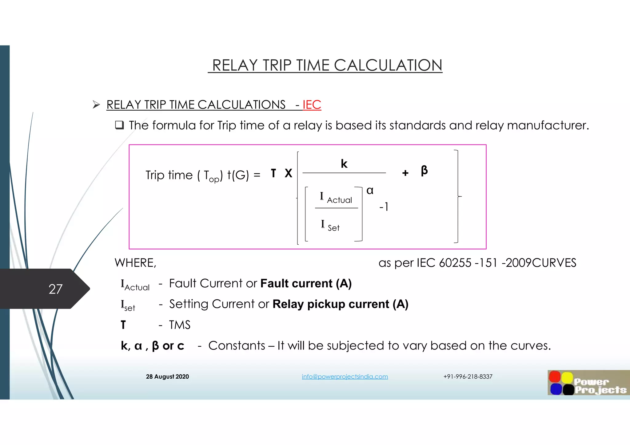
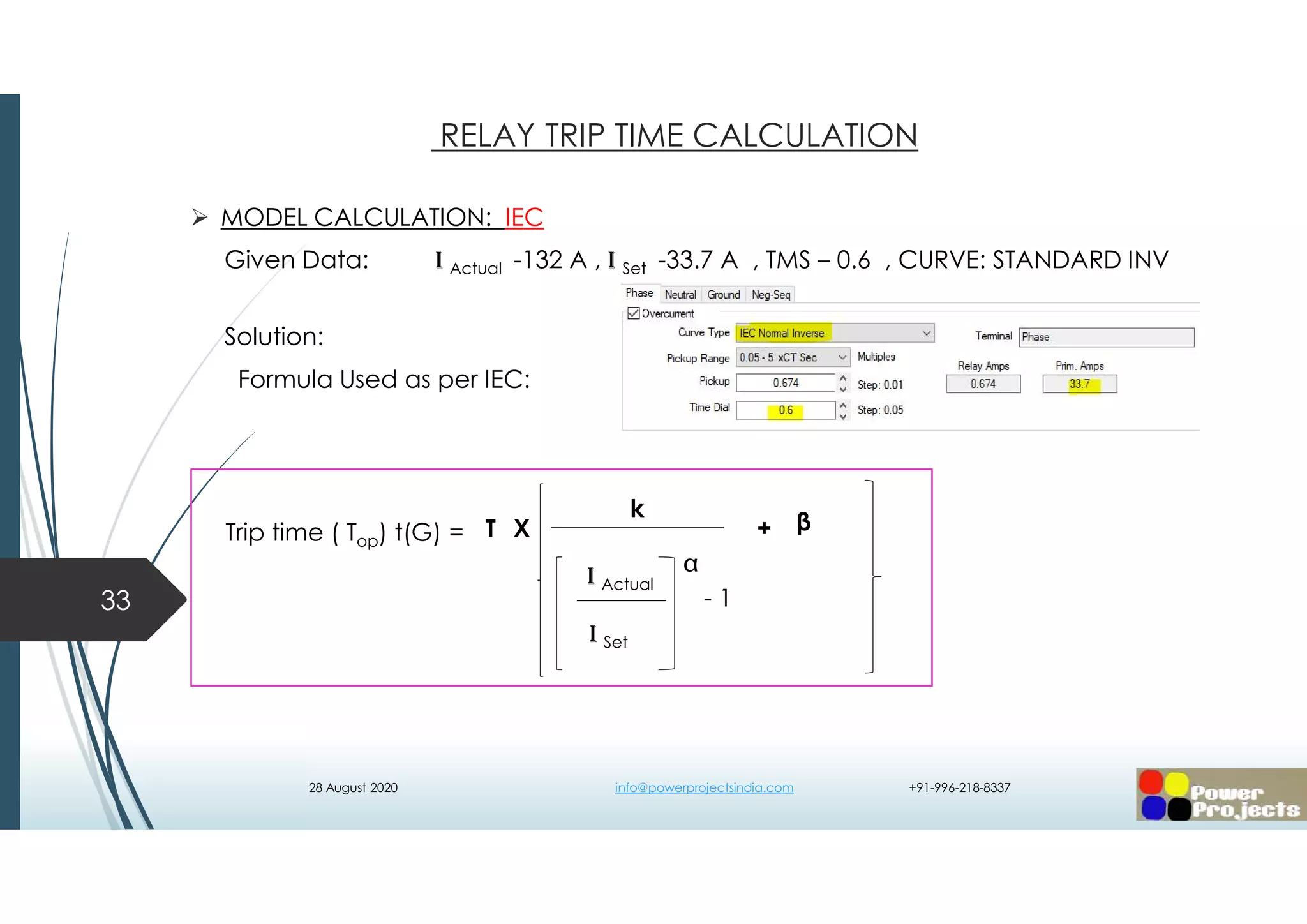
![ RELAY TRIP TIME CALCULATIONS - IEC
WHERE, as per IEC 60255 -151 -2009CURVES
- PLUG SETTING MULTIPLIER [ PSM ]28
RELAY TRIP TIME CALCULATION
I Actual
I Set
-1
k
I Actual
I Set
T βX +Trip time ( Top) t(G) =
28 August 2020 info@powerprojectsindia.com +91-996-218-8337](https://image.slidesharecdn.com/ipsa-mvrelayco-ordiantionshaikadam-200828023731/75/Ipsa-mv-relay-co-ordiantion-shaik-adam-28-2048.jpg)
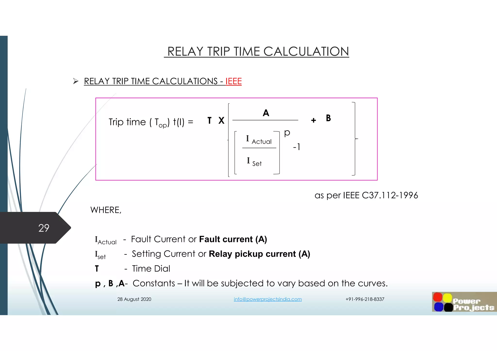
![ RELAY TRIP TIME CALCULATIONS - IEEE
WHERE, as per IEEE C37.112-1996
- PLUG SETTING MULTIPLIER [ PSM ]30
RELAY TRIP TIME CALCULATION
I Actual
I Set
-1
A
I Actual
I Set
p
T BX +Trip time ( Top) t(I) =
28 August 2020 info@powerprojectsindia.com +91-996-218-8337](https://image.slidesharecdn.com/ipsa-mvrelayco-ordiantionshaikadam-200828023731/75/Ipsa-mv-relay-co-ordiantion-shaik-adam-30-2048.jpg)


![ TOC CURVES - PRIOIRITY SELECTION: [51] ( TRIPPING TIME MODERATE)
SOURCE / INCOMER SIDE - STANDARD INVERSE.
EQUIPMENT LOAD SIDE- LONG INVERSE/ EXTREME INVERSE / VERY INVERSE.
IOC - PRIOIRITY SELECTION: [50] ( TRIPPING TIME IMMEDIATE)
SOURCE / INCOMER /EUIPMENT SIDE - DMT - TIME DELAY / TIME GRADE IS
DESIRED.
LOAD SIDE – NO INTENTIONAL TIME DELAY ( INHERENT TIME DELAY)
36
RELAY TRIP TIME CALCULATION
28 August 2020 info@powerprojectsindia.com +91-996-218-8337](https://image.slidesharecdn.com/ipsa-mvrelayco-ordiantionshaikadam-200828023731/75/Ipsa-mv-relay-co-ordiantion-shaik-adam-36-2048.jpg)
![ TOC CURVES (IDMT) : [51] ( TRIPPING TIME MODERATE) As per ALSTOM P141
Phase TOC [51]
Neutral TOC [51N]
Ground TOC [51G]
Sensitive Ground TOC [51SEN]
Negative Sequence TOC [51NS]
37
RELAY TRIP TIME CALCULATION
PROTECTION PHASE NEUTRAL GROUND SEN .GROUND NEG SEQ
TOC (IDMT) 51 51N 51G 51SG 51NS
LOCATION (TOC)
PREFERRED
ALL TRANSFORMER
MOTOR/
NEUTRAL
FEEDER -- --
28 August 2020 info@powerprojectsindia.com +91-996-218-8337](https://image.slidesharecdn.com/ipsa-mvrelayco-ordiantionshaikadam-200828023731/75/Ipsa-mv-relay-co-ordiantion-shaik-adam-37-2048.jpg)
![ IOC (DMT) : [50] ( TRIPPING TIME IMMEDIATE) as per ALSTOM P141
Phase IOC [50I]
Neutral IOC [50N]
Ground IOC [50G]
Sensitive Ground IOC [50SG]
Negative Sequence IOC [50NS]
38
RELAY TRIP TIME CALCULATION
PROTECTION PHASE NEUTRAL GROUND SEN .GROUND NEG SEQ
INSTANTANEOUS 50I 50N 50G 50SG 50NS
DEFINITE/SHORT TIME
(DMT)
50D 50D 50D 50D 50D
LOCATION (INSTANT)
PREFERRED
LOAD SIDE/END
EQUIPMENT
TRANFORMER/
INCOMER
FEEDER -- --
28 August 2020 info@powerprojectsindia.com +91-996-218-8337](https://image.slidesharecdn.com/ipsa-mvrelayco-ordiantionshaikadam-200828023731/75/Ipsa-mv-relay-co-ordiantion-shaik-adam-38-2048.jpg)

![ PROTECTION CO-ORDINATION : OVERCURRENT [51] AND EARTH FAULT [51G/N]
EQUIPMENTS TO BE COVERED :
TRANSFORMER
MOTOR
41
EQUIPMENTS DETAILS
28 August 2020 info@powerprojectsindia.com +91-996-218-8337](https://image.slidesharecdn.com/ipsa-mvrelayco-ordiantionshaikadam-200828023731/75/Ipsa-mv-relay-co-ordiantion-shaik-adam-41-2048.jpg)


![CTI: IEEE242 – 15.5
When plotting coordination curves, certain time intervals should be maintained
between the curves of various protective devices to ensure correct selective
operation and to reduce nuisance tripping. Without adequate CTIs, these
protective devices could trip incorrectly.
49
CO-ORDINATION TIME INTERVAL [ CTI ]
28 August 2020 info@powerprojectsindia.com +91-996-218-8337](https://image.slidesharecdn.com/ipsa-mvrelayco-ordiantionshaikadam-200828023731/75/Ipsa-mv-relay-co-ordiantion-shaik-adam-49-2048.jpg)
![ CTI:
When coordinating inverse time overcurrent relays, the time interval
according to ANSI/ IEEE Std-242 is usually 0.3 to 0.4 seconds. This interval is
measured between relays in series at the instantaneous setting of the
load side feeder circuit breaker relay and upcoming incomer relays.
The recommended time has the following components:
• circuit breaker opening time (5 cycles): 0.10 seconds
• relay overtravel: 0.10 seconds ( Electromechanical relay)
• safety factor for CT saturation, setting errors, etc.: 0.22 seconds.
NOTE: CYCLE( T) = 1/ f , Where f- supply frequency [50Hz], then 1 cycle
=1/50 , =20ms (0.02 seconds).
50
CO-ORDINATION TIME INTERVAL [ CTI ]
28 August 2020 info@powerprojectsindia.com +91-996-218-8337](https://image.slidesharecdn.com/ipsa-mvrelayco-ordiantionshaikadam-200828023731/75/Ipsa-mv-relay-co-ordiantion-shaik-adam-50-2048.jpg)
![ CTI:
The recommended time has the following components:
Traditional Time ( 200ms)
Relay Sensing time : 20ms
Breaker opening time : 40ms
CT saturation, setting error : 20ms
Safety factor / Margin : 100ms
So total 180ms ≈ 200ms or 250ms is provided between series relay’s time
discrimination.
51
CO-ORDINATION TIME INTERVAL [ CTI ]
28 August 2020 info@powerprojectsindia.com +91-996-218-8337](https://image.slidesharecdn.com/ipsa-mvrelayco-ordiantionshaikadam-200828023731/75/Ipsa-mv-relay-co-ordiantion-shaik-adam-51-2048.jpg)
![ CTI:
The CTI time interval is changing with respect to the country where the
project is executed and plant’s complex network.
52
CO-ORDINATION TIME INTERVAL [ CTI ]
28 August 2020 info@powerprojectsindia.com +91-996-218-8337](https://image.slidesharecdn.com/ipsa-mvrelayco-ordiantionshaikadam-200828023731/75/Ipsa-mv-relay-co-ordiantion-shaik-adam-52-2048.jpg)
![ CTI CALCULATION:
CTI =
WHERE,
tR – Relay Timing Error IN %
tCT – CT Error IN %
tOP – Breaker Operation Time Max.1000ms( Changeable With Country / Client)
When Fault Occurred The Immediate Breaker Operate To Isolate.
tOV – Over Travel Time of Electro-Mechanical Relay ( Not Applicable for
Numerical relay)
53
CO-ORDINATION TIME INTERVAL [ CTI ]
2tR + tCT
100
X tOP + tOv + tCB + tAT + tS
28 August 2020 info@powerprojectsindia.com +91-996-218-8337](https://image.slidesharecdn.com/ipsa-mvrelayco-ordiantionshaikadam-200828023731/75/Ipsa-mv-relay-co-ordiantion-shaik-adam-53-2048.jpg)
![ CTI CALCULATION:
CTI =
WHERE,
tCB – Breaker Opening Time ( Vendor catalogue) - 40-45ms.
tAT – Additional Time required by the relay.
tS – Safety factor
When the overcurrent relays have independent definite time delay
characteristics, it is not necessary to include the allowance for CT error. Hence:
54
CO-ORDINATION TIME INTERVAL [ CTI ]
2tR + tCT
100
X tOP + tOv + tCB + tAT + tS
28 August 2020 info@powerprojectsindia.com +91-996-218-8337](https://image.slidesharecdn.com/ipsa-mvrelayco-ordiantionshaikadam-200828023731/75/Ipsa-mv-relay-co-ordiantion-shaik-adam-54-2048.jpg)
![ CONCLUSION ON CTI :
CTI =
BETWEEN DOWNSTREAM AND UPSTREAM RELAYS CTI
55
CO-ORDINATION TIME INTERVAL [ CTI ]
2tR + tCT
100
X tOP + tOv + tCB + tAT + tS
RELAY TYPE CTI ( ms)
STATIC RELAY / SST MAX 350 NO MIN
ELECTRO MECHANICAL RELAY MIN 400
NUMERICAL RELAY 200 TO 300
28 August 2020 info@powerprojectsindia.com +91-996-218-8337](https://image.slidesharecdn.com/ipsa-mvrelayco-ordiantionshaikadam-200828023731/75/Ipsa-mv-relay-co-ordiantion-shaik-adam-55-2048.jpg)
![ EXAMPLE SCENARIOS:
SCENARIO 1: Load To Source All Feeders are
Cables And Source Incomer [CB7]
Is Located At Plant Premises.
CTI : 200ms each stage .
56
CO-ORDINATION TIME INTERVAL [ CTI ]
28 August 2020 info@powerprojectsindia.com +91-996-218-8337](https://image.slidesharecdn.com/ipsa-mvrelayco-ordiantionshaikadam-200828023731/75/Ipsa-mv-relay-co-ordiantion-shaik-adam-56-2048.jpg)
![ EXAMPLE SCENARIOS:
SCENARIO 2: Load To Source All Feeders are
Cables And Source Incomer [CB4]
Is Located At Plant Premises.
CTI : Even a single cable always maintain
an additional time interval to avoid nuisance
relations with utility.
So CTI is 600ms at Relay-5 [ utility ]when its
Down stream incomer relay Relay-4 has CTI 400ms.
57
CO-ORDINATION TIME INTERVAL [ CTI ]
28 August 2020 info@powerprojectsindia.com +91-996-218-8337](https://image.slidesharecdn.com/ipsa-mvrelayco-ordiantionshaikadam-200828023731/75/Ipsa-mv-relay-co-ordiantion-shaik-adam-57-2048.jpg)
![ EXAMPLE SCENARIOS:
SCENARIO 3: Load To Source All Feeders are
Cables and has Transformer [CB5]
Is Located At Plant Premises.
CTI : In order to avoid tripping Transformer HV frequently
respect to LV faults 50- 100ms additional CTI is
added at Transformer HV Relay-5. Avoid frequent
In-rush currents on transformer.
So CTI is 500ms at Relay-5 [ Transformer HV ]when its
Down stream Transformer LV Relay-4 has CTI 400ms.
58
CO-ORDINATION TIME INTERVAL [ CTI ]
28 August 2020 info@powerprojectsindia.com +91-996-218-8337](https://image.slidesharecdn.com/ipsa-mvrelayco-ordiantionshaikadam-200828023731/75/Ipsa-mv-relay-co-ordiantion-shaik-adam-58-2048.jpg)