Downloaded 146 times

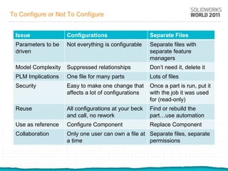
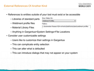


The document outlines strategies for designing durable models using SolidWorks, focusing on automation techniques that minimize user intervention through API programming or partner products. Key topics include avoiding unwanted parent-child relationships, considerations for automating weldments and sheet metal, and recommendations for simulating and drawing automation. It emphasizes the importance of understanding the target audience and appropriately simplifying models to enhance stability and usability in automation.


![SCRM[1]](https://cdn.slidesharecdn.com/ss_thumbnails/6541d089-07f6-4578-95aa-2aba974be43e-151012061047-lva1-app6892-thumbnail.jpg?width=640&height=640&fit=bounds)