The document discusses UML component diagrams, which model software components and their interfaces and dependencies. Key points include:
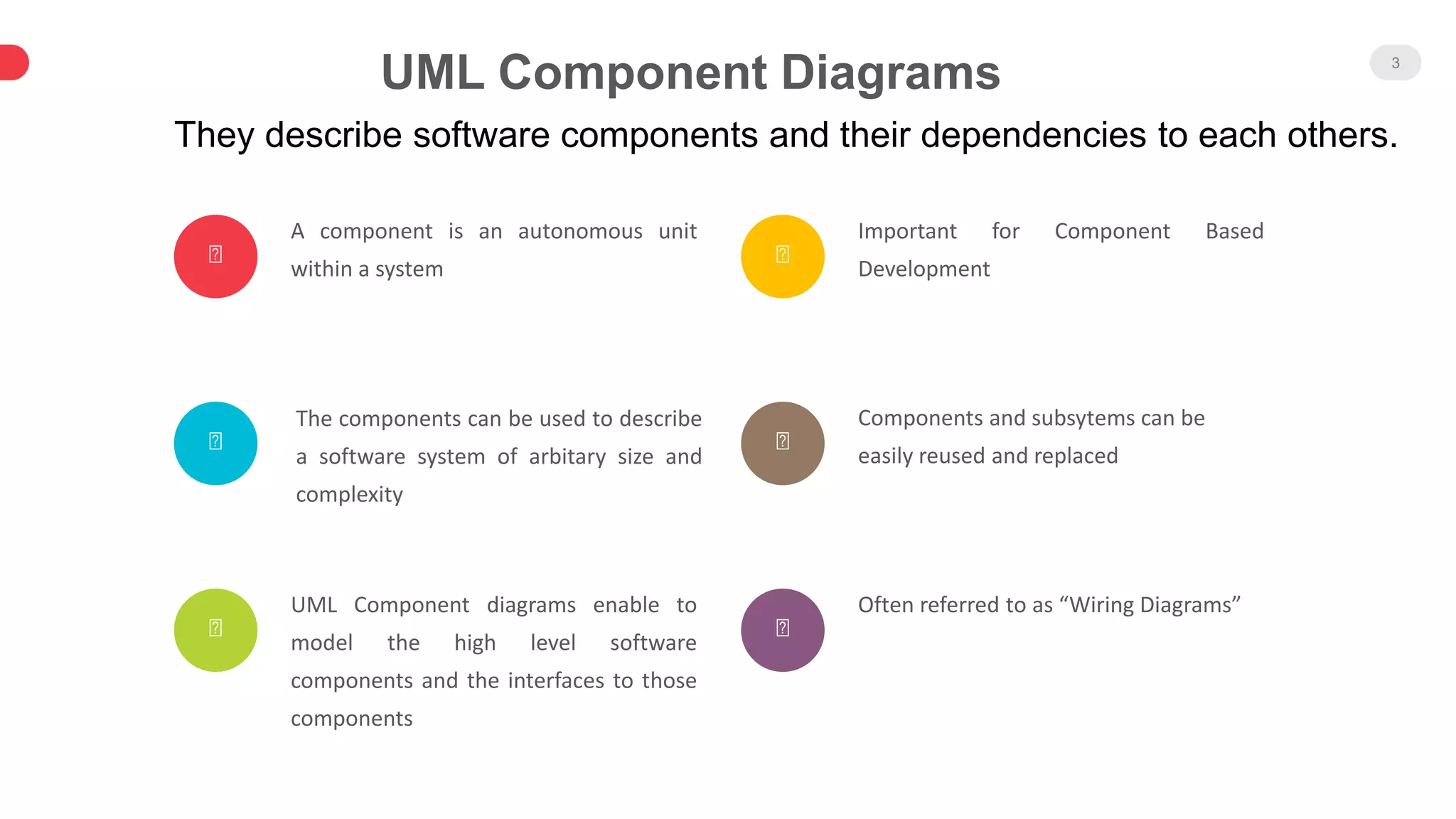
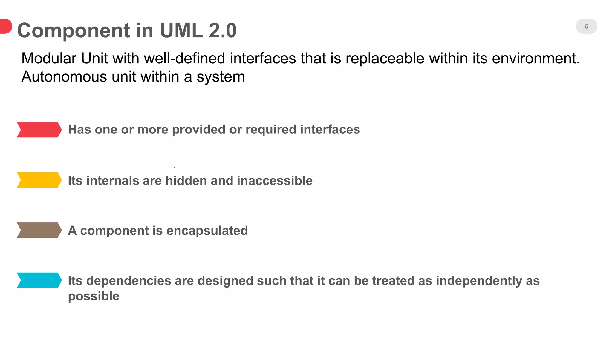
- A component is an autonomous unit that provides and requires interfaces. Components can be reused and replaced.
- Component diagrams show high-level software components and their interfaces. They are often called "wiring diagrams" as they depict dependencies between components.
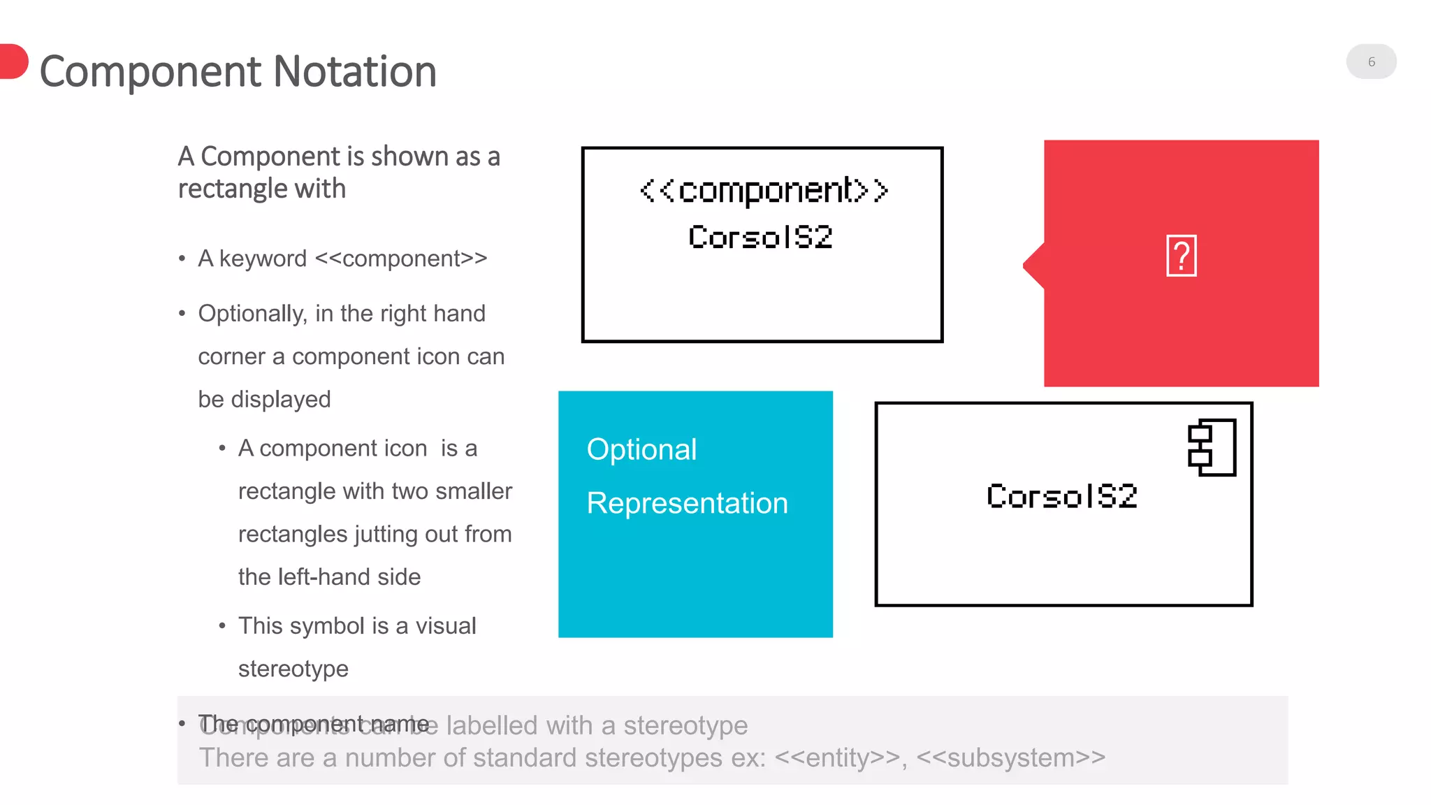
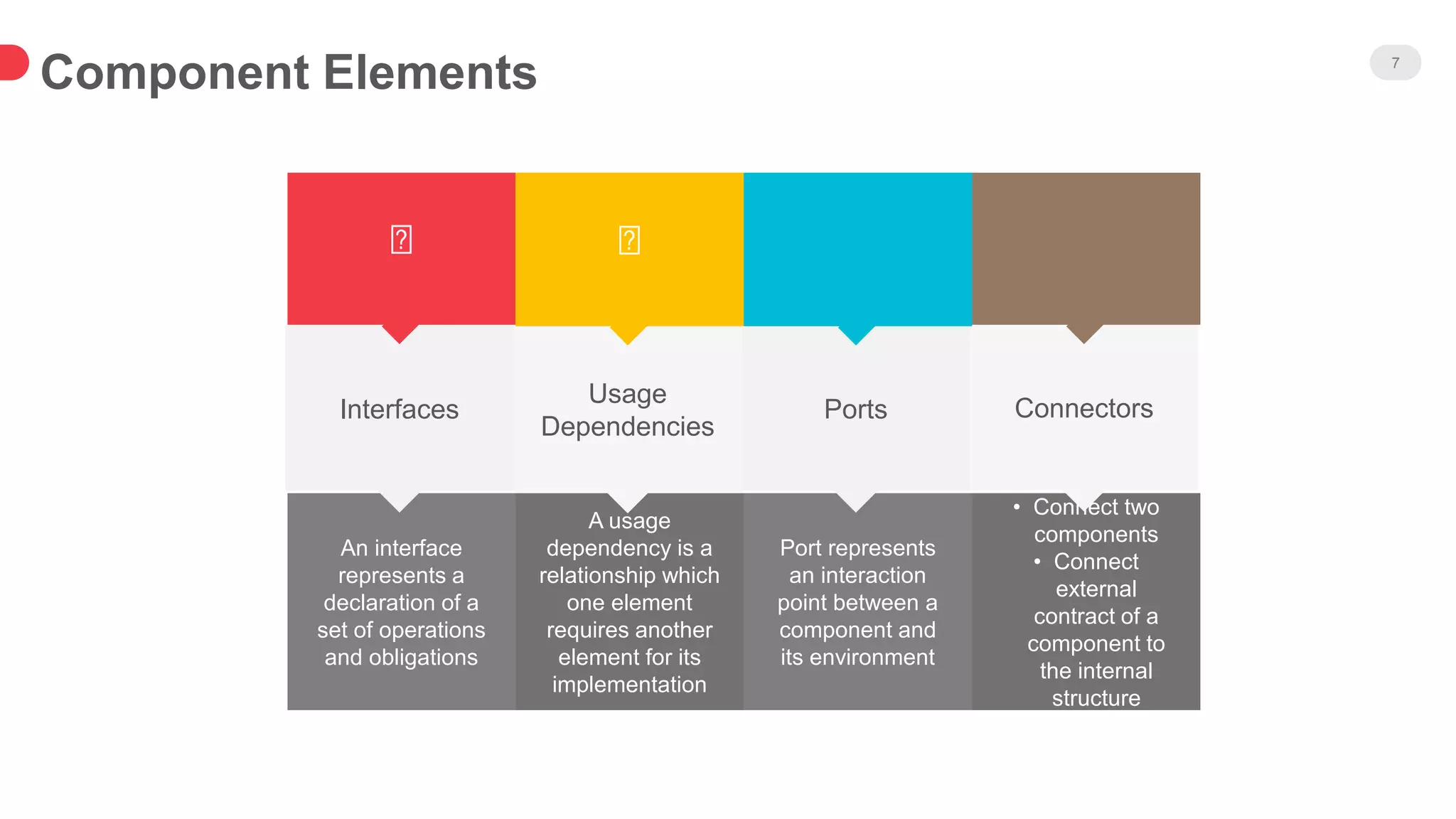
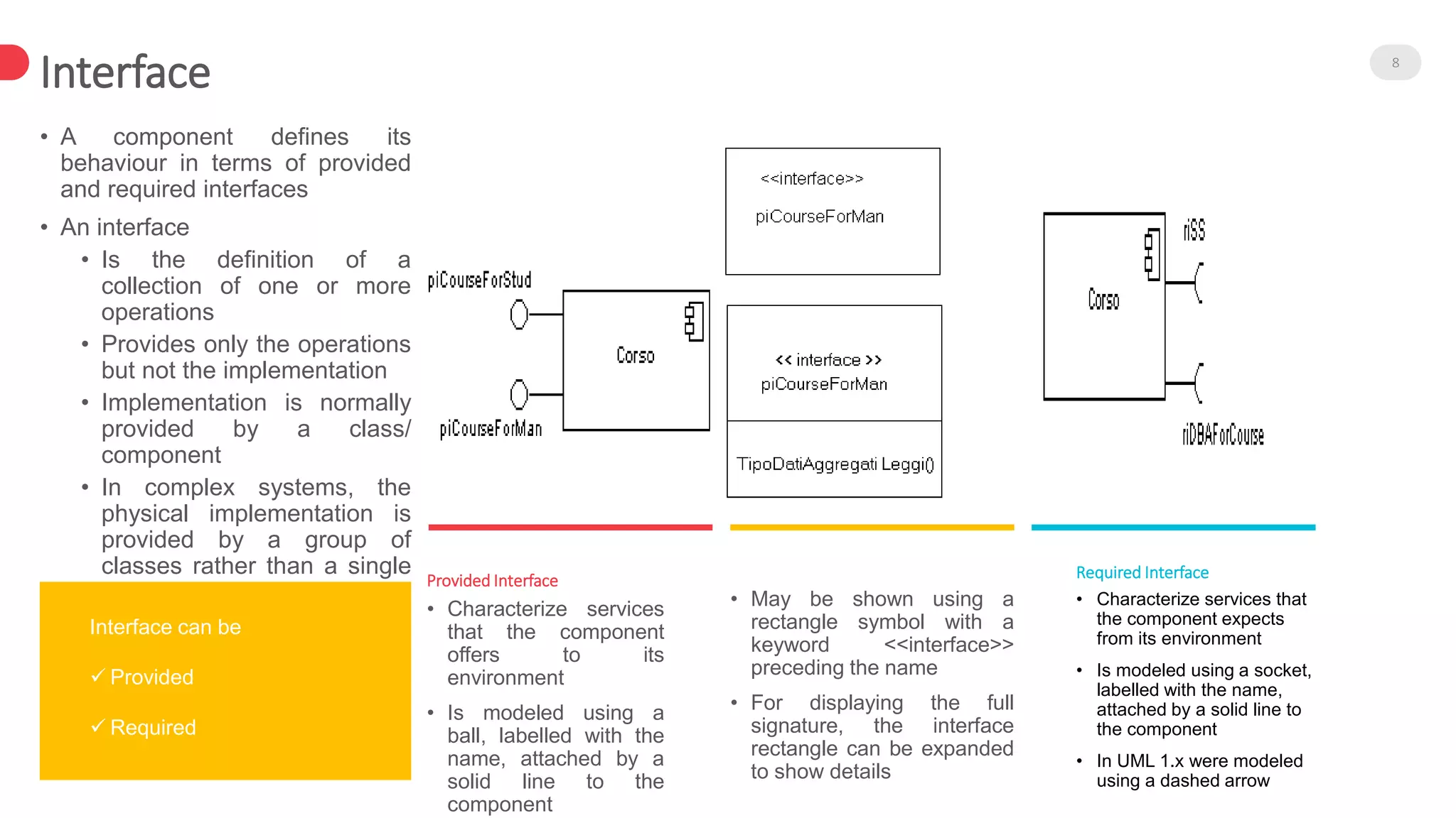
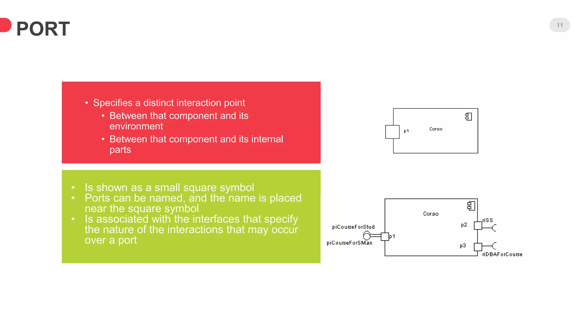
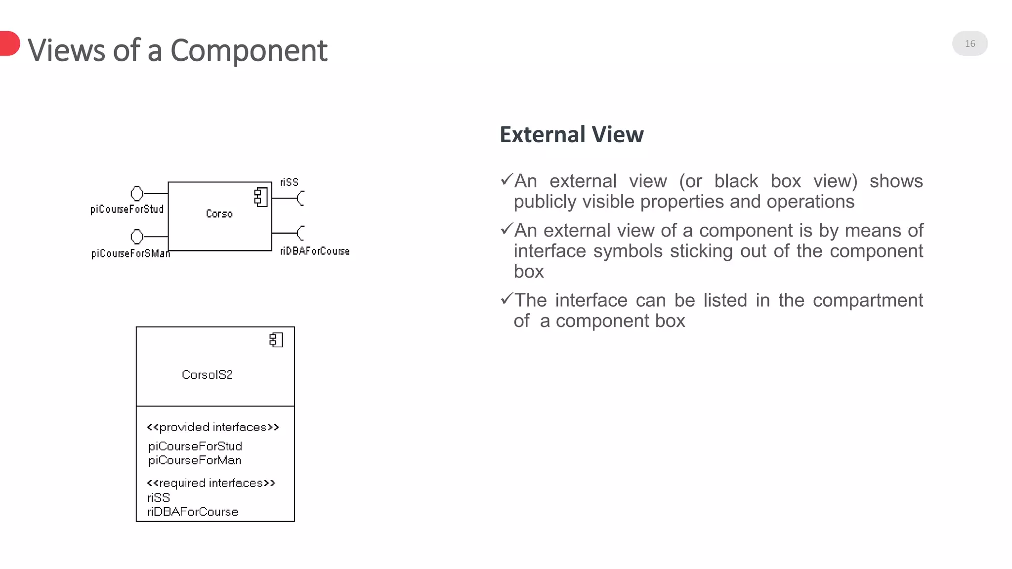
- Components have provided and required interfaces, ports, and usage dependencies. Interfaces define collections of operations without implementation details.
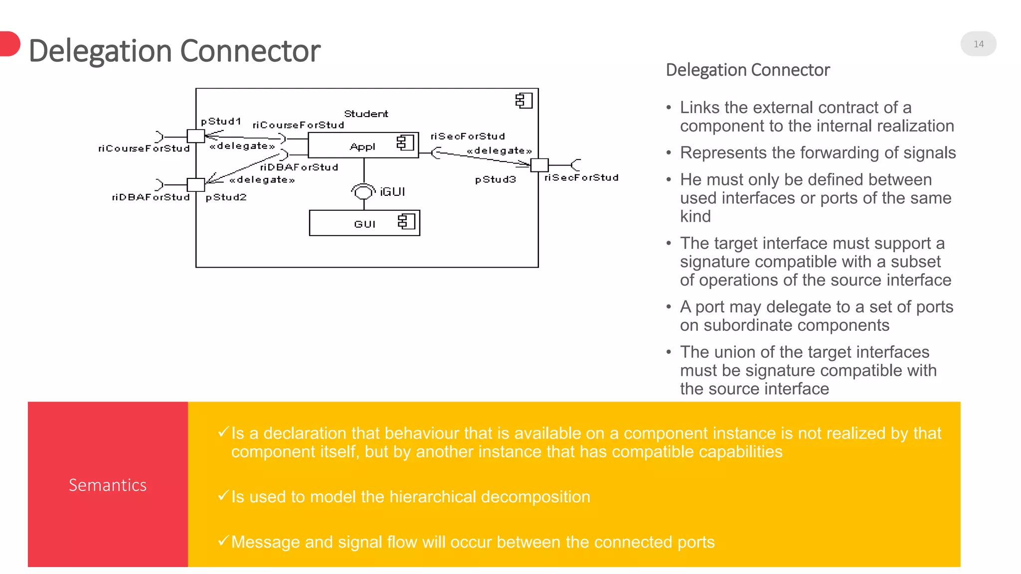
- Connectors link compatible required and provided interfaces to show how components interact. Assembly connectors pass signals, while delegation connectors forward signals internally.
- Components can be shown externally through their interfaces or internally with nested realizing classes