Download as PDF, PPTX
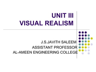

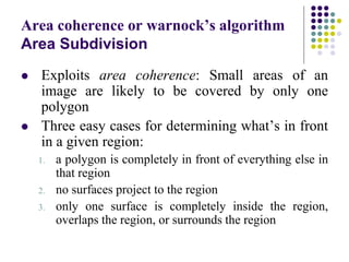
![Z-BUFFER ALGORITHM:
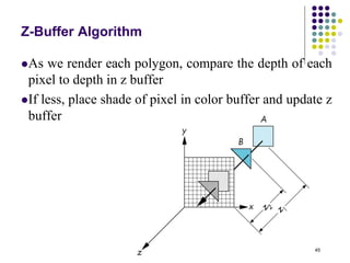
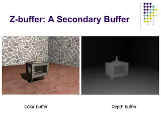
• Its an extension of Frame Buffer
• Display is always stored on Frame Buffer
• Frame Buffer stores information of each and every
pixel on the screen
• Bits (0, 1) decide that the pixel will be ON or OFF
• Z- Buffer apart from Frame buffer stores the depth
of pixel
• After analyzing the data of the overlapping
polygons, pixel closer to the eye will be updated
• Resolution of X,Y => Array[X,Y]](https://image.slidesharecdn.com/unit3visualrealism-180828100820/85/Unit-3-visual-realism-48-320.jpg)
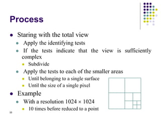
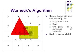
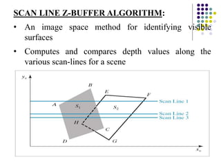
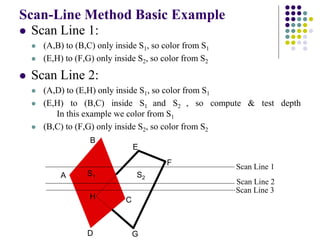

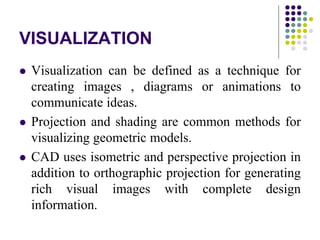
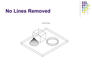
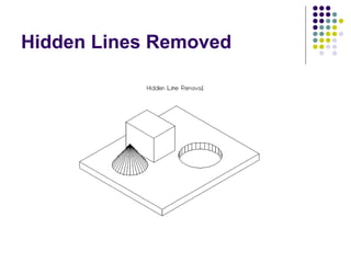
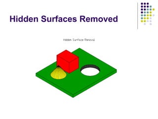
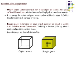
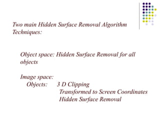
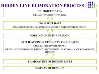
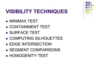
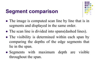
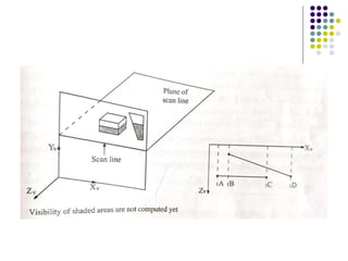
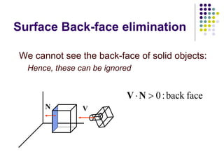
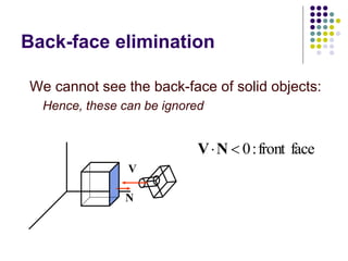
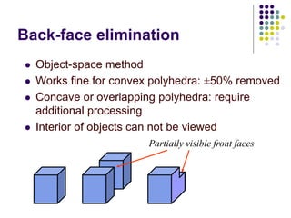
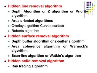
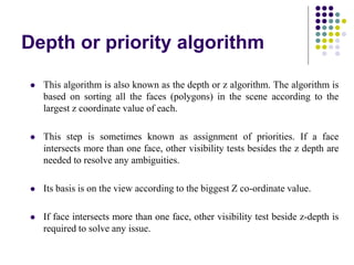
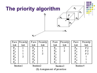
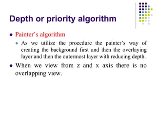
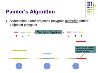
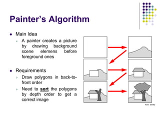
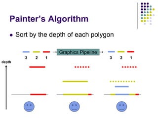
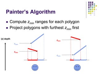
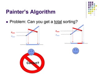
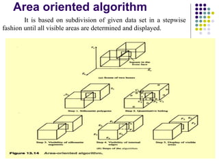
The document discusses various techniques for achieving visual realism in 3D modeling and visualization. It describes methods for projecting 3D objects into 2D views, including orthographic projection, isometric projection, and perspective projection. Techniques for removing hidden lines and surfaces like backface elimination are covered. The document also discusses algorithms for hidden surface removal including the depth/priority, painter's, area-oriented, and scanline algorithms. Applications of visualization like robot simulations, CNC programming, and scientific computing are also mentioned.