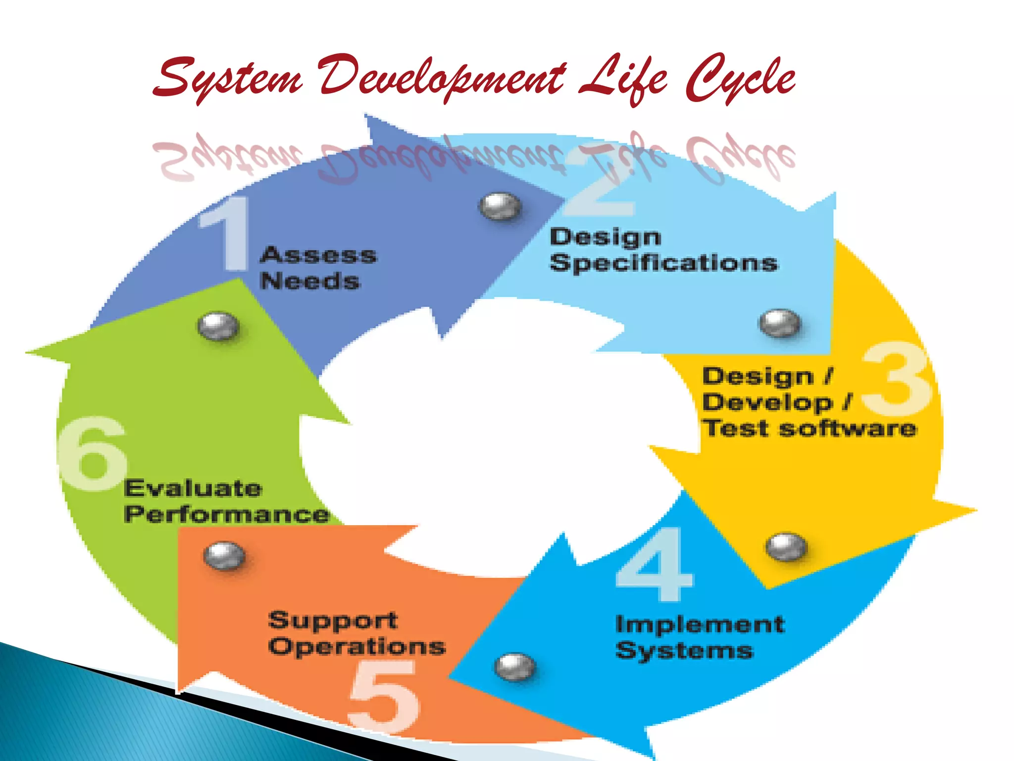
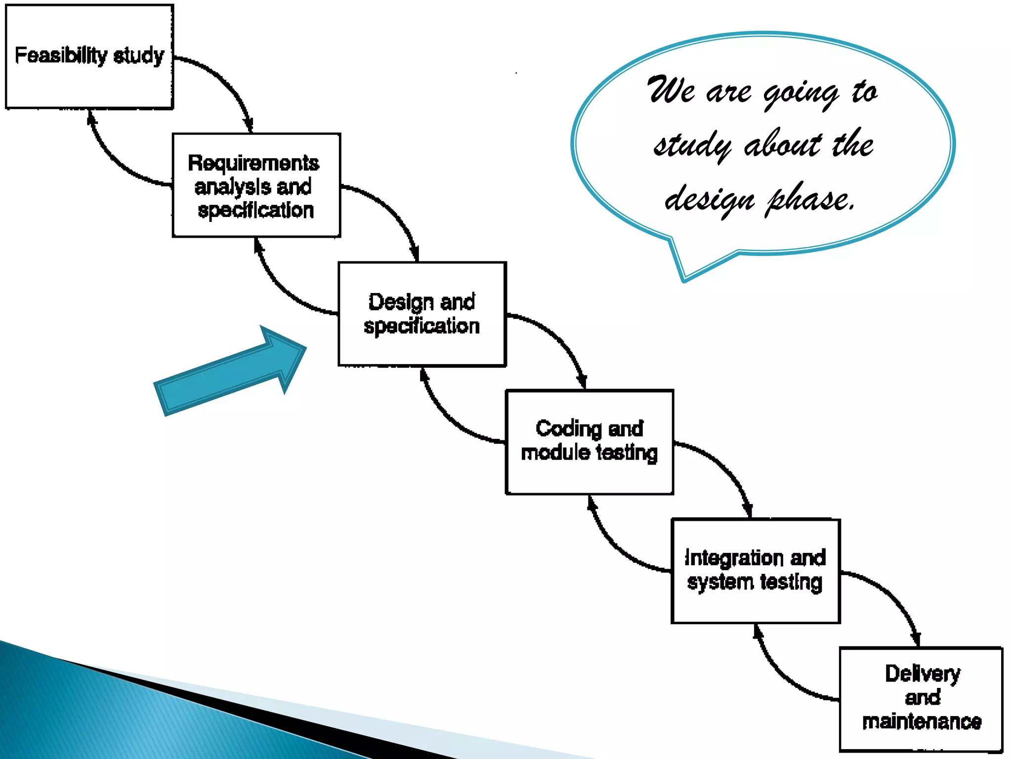
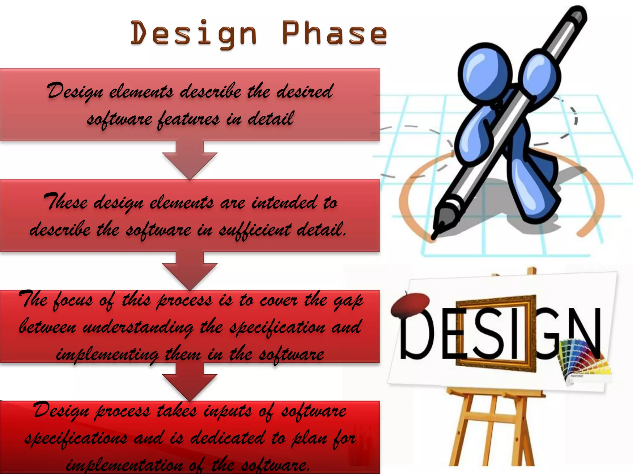
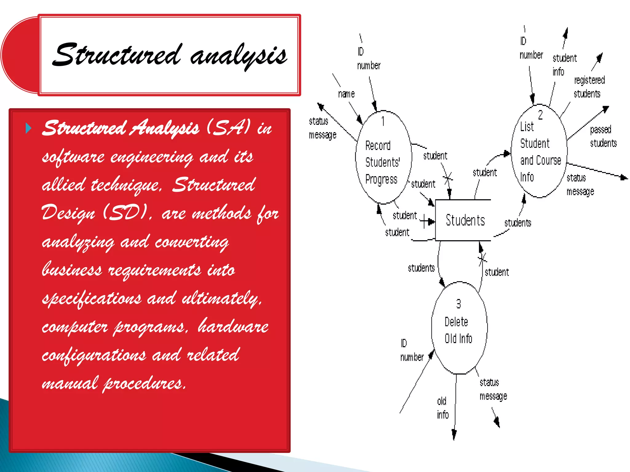
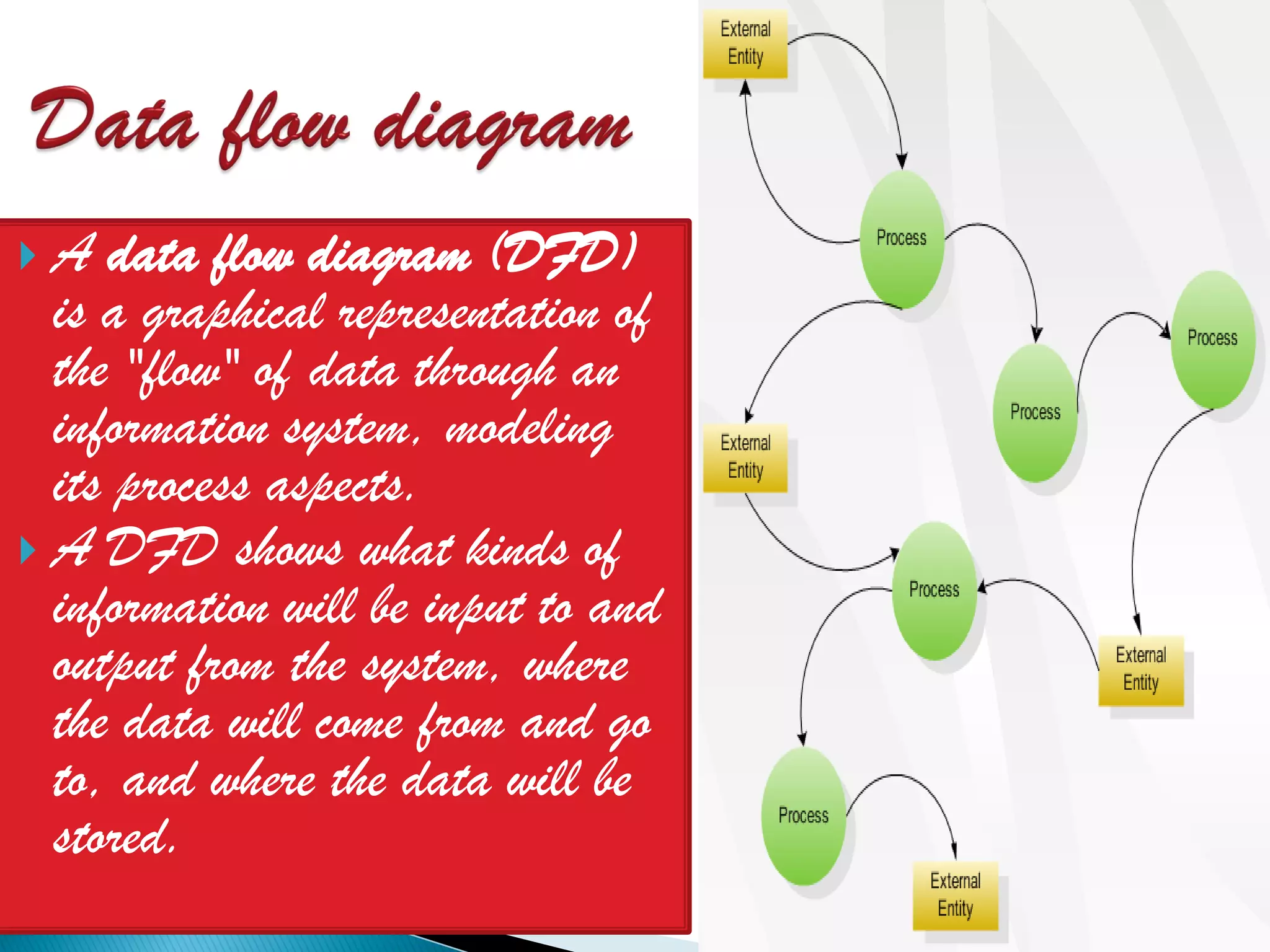
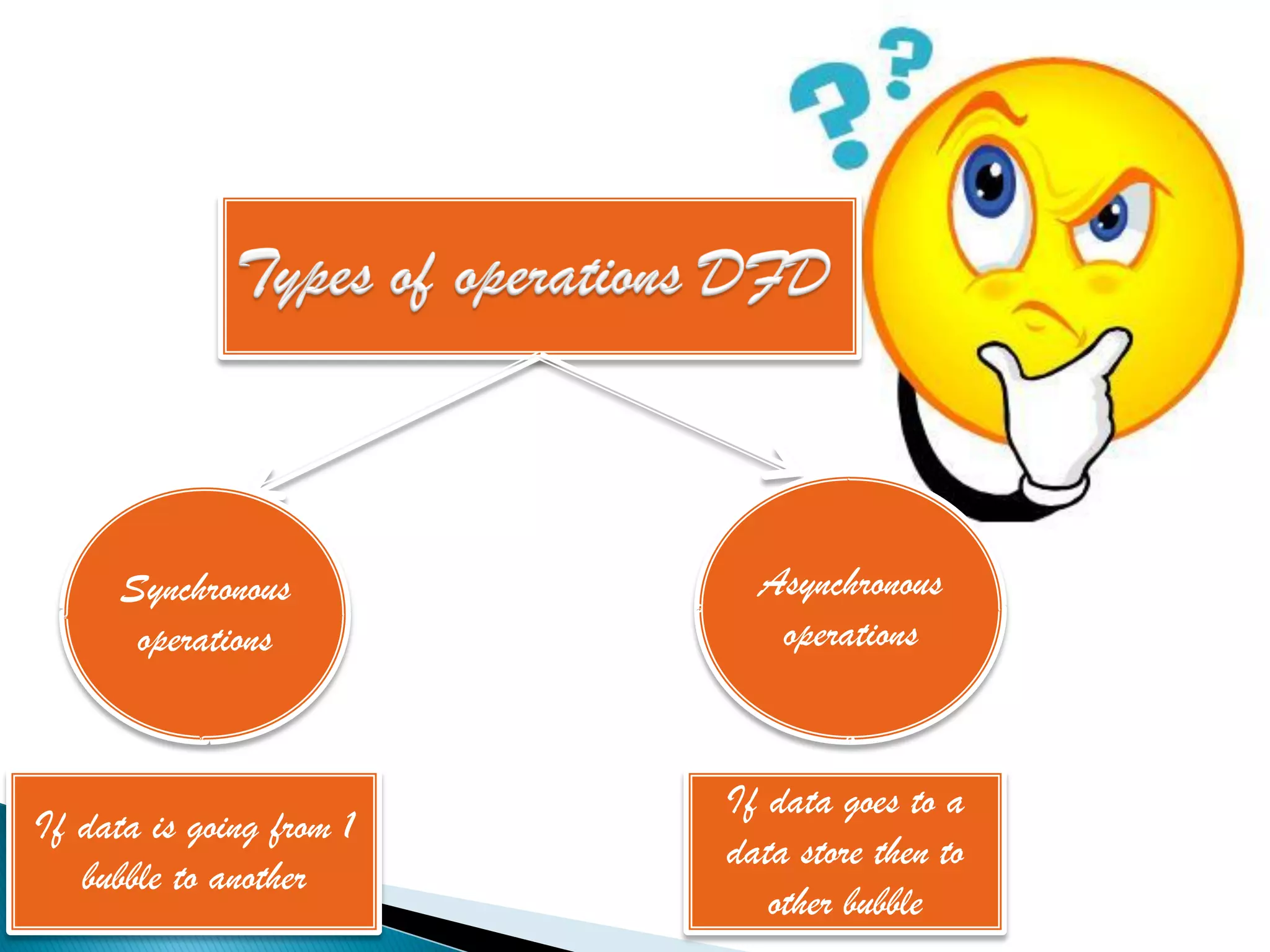
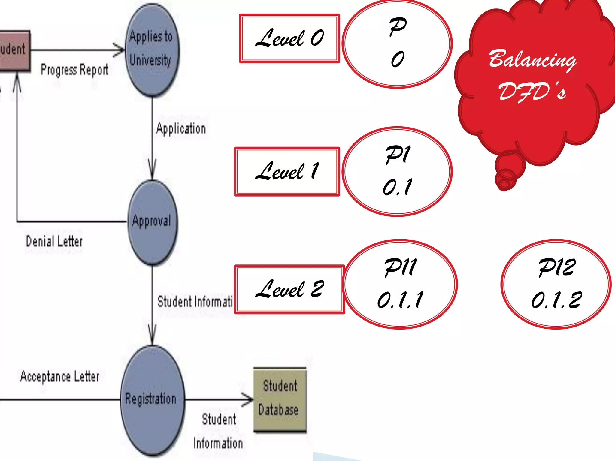
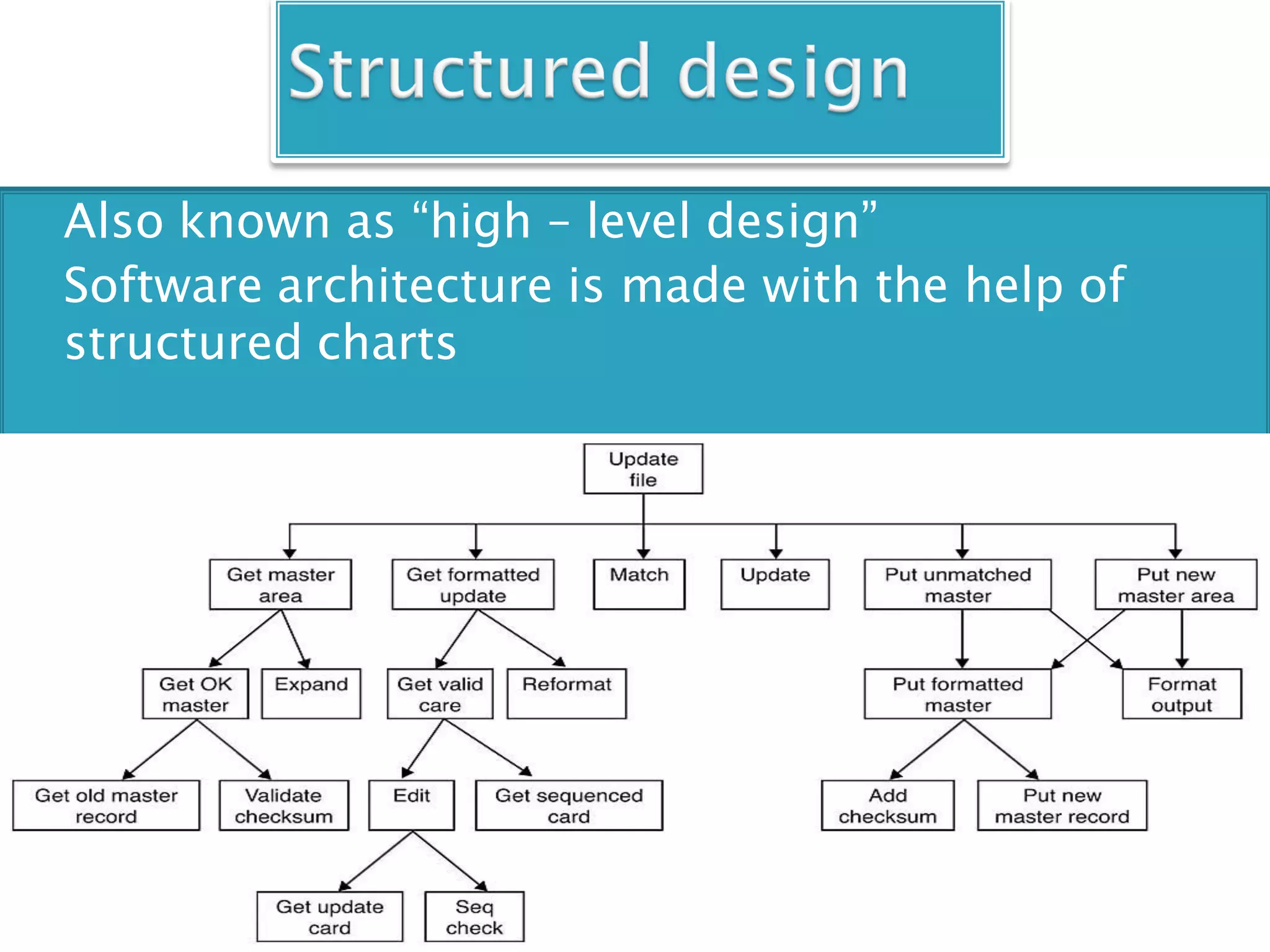
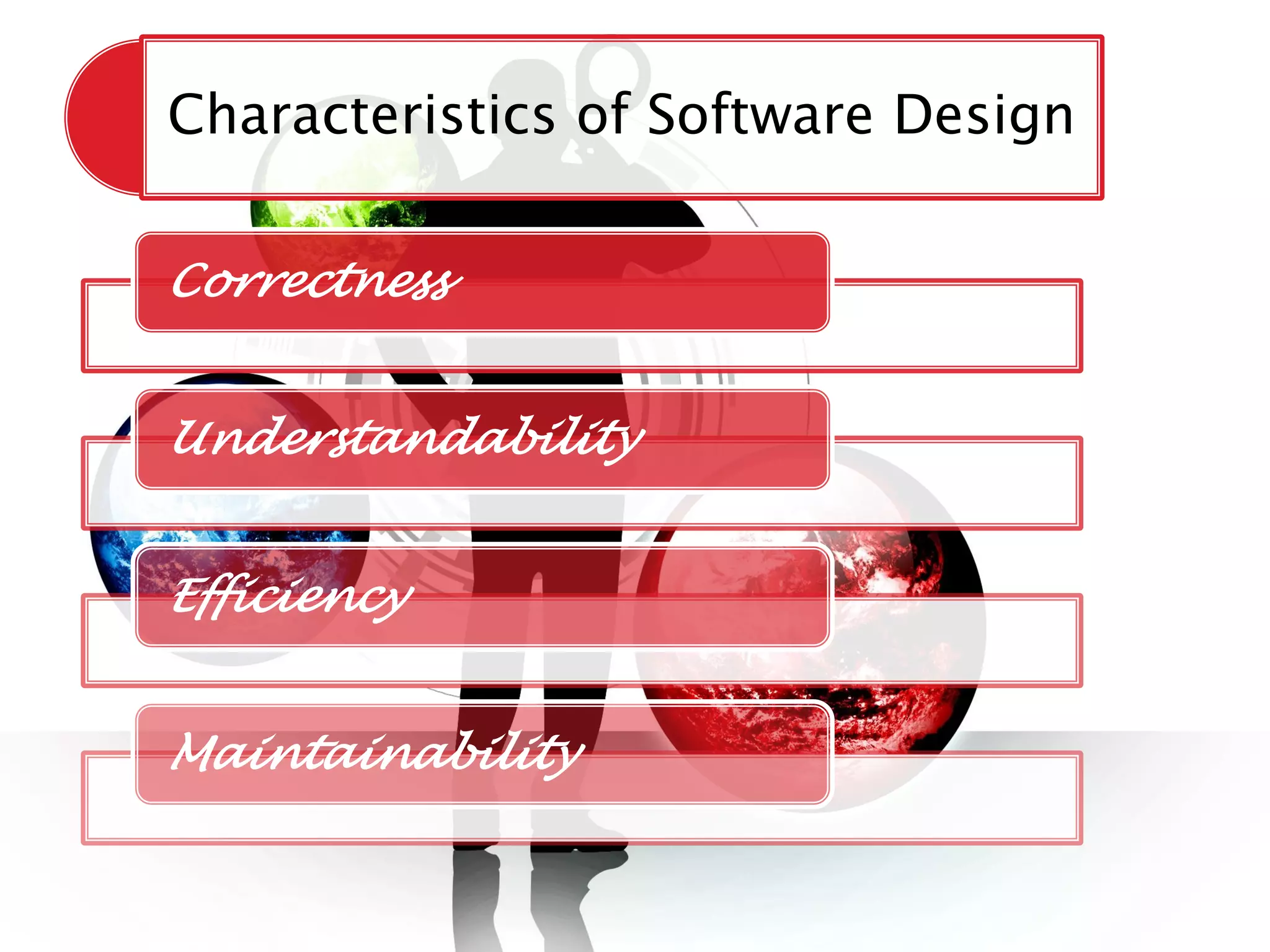
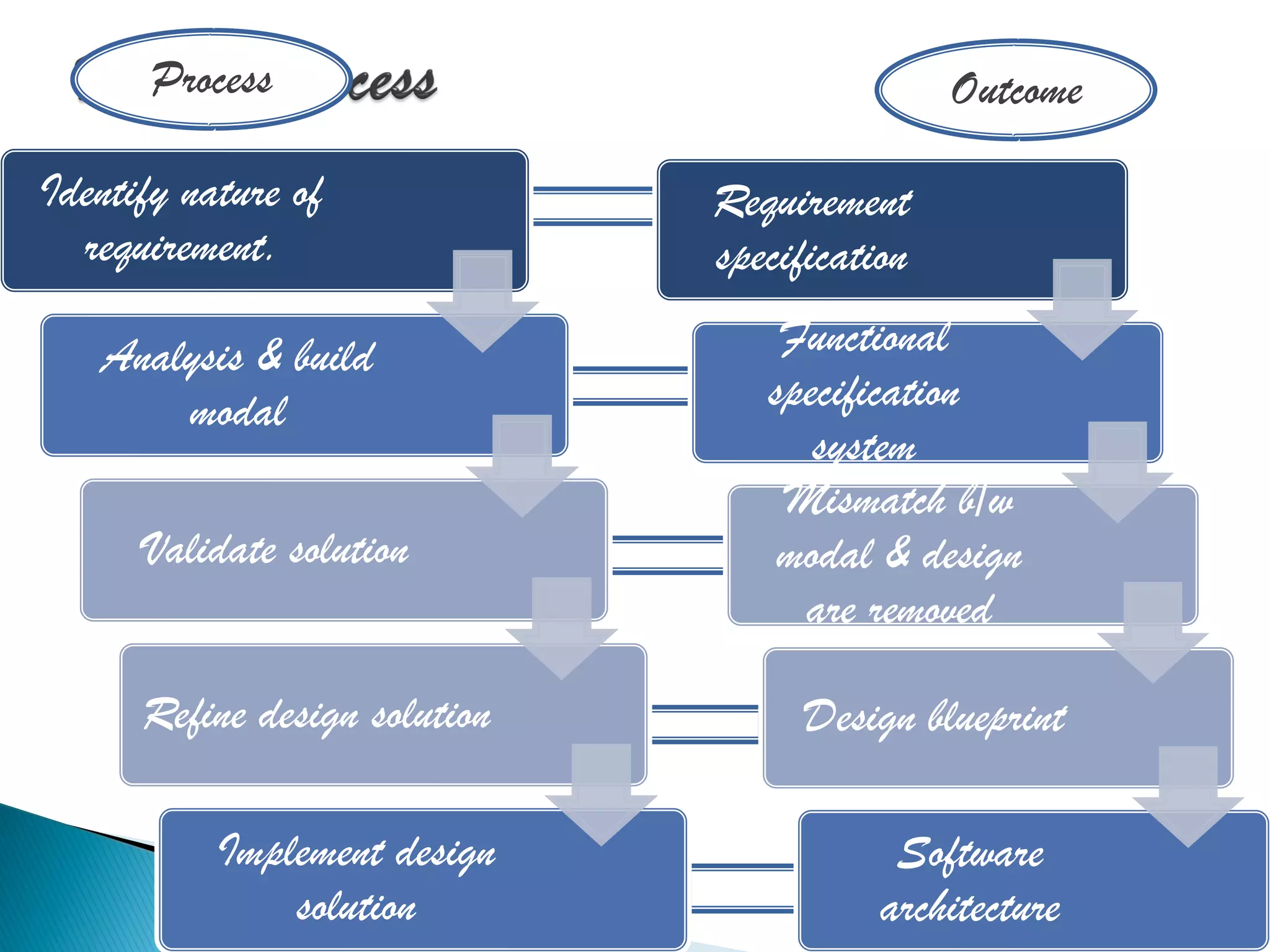
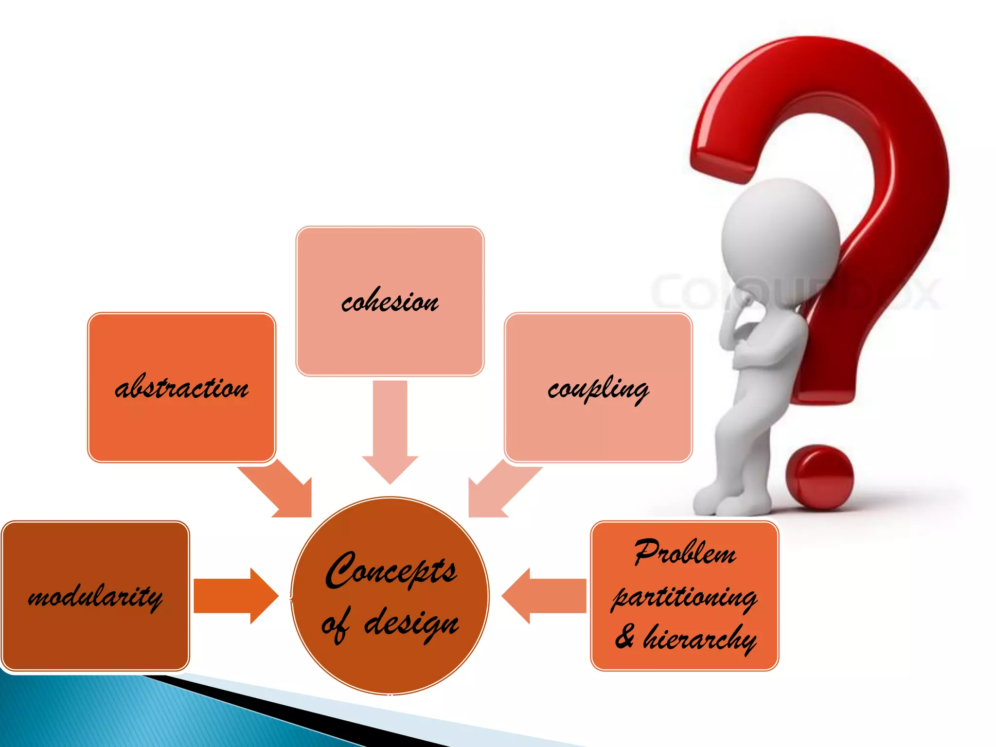
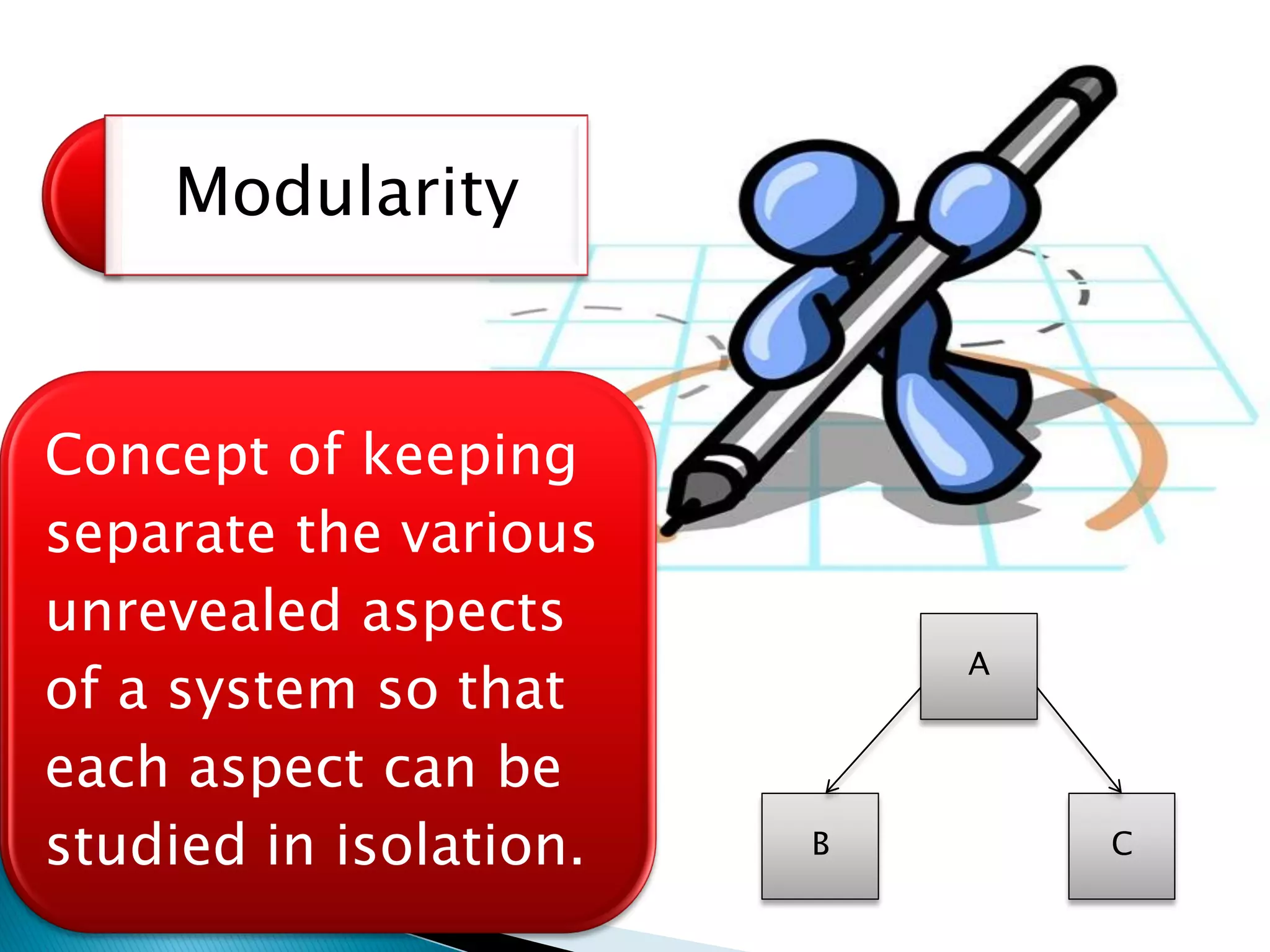
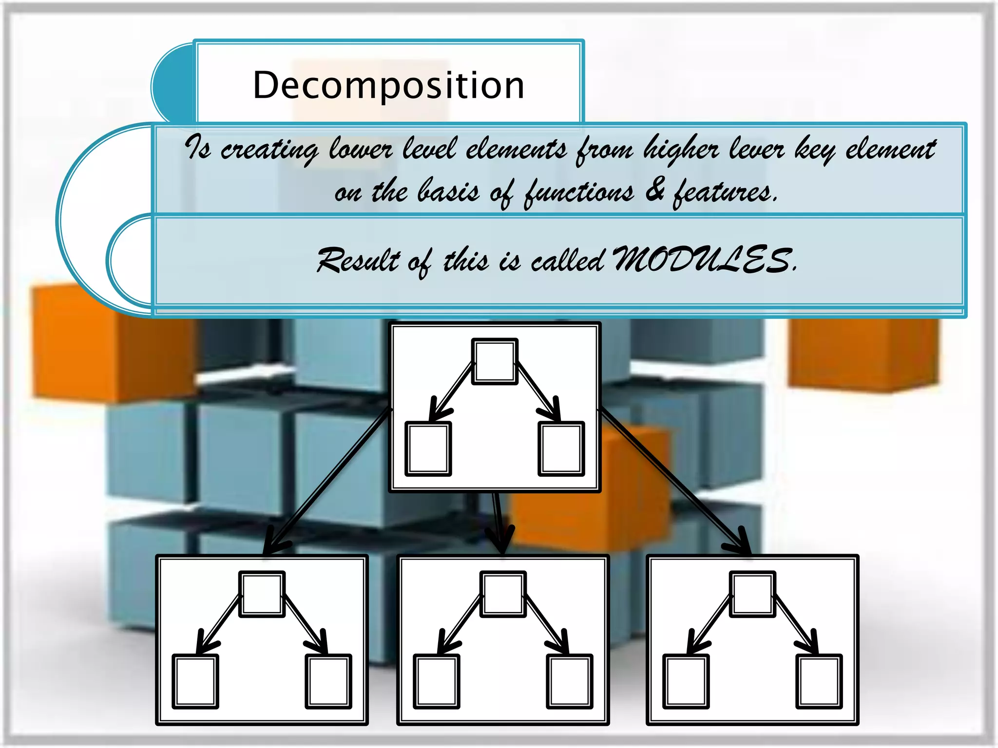
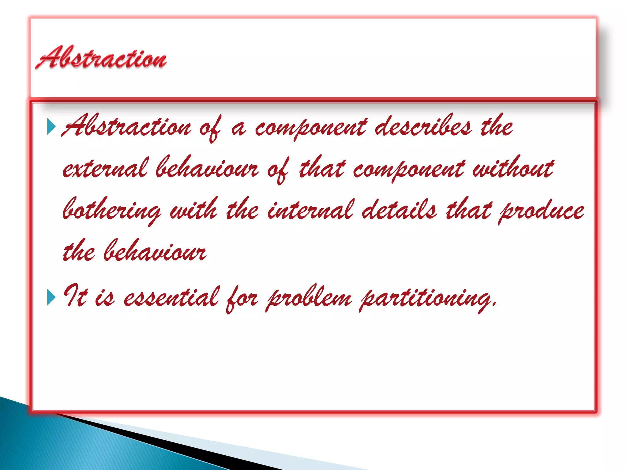
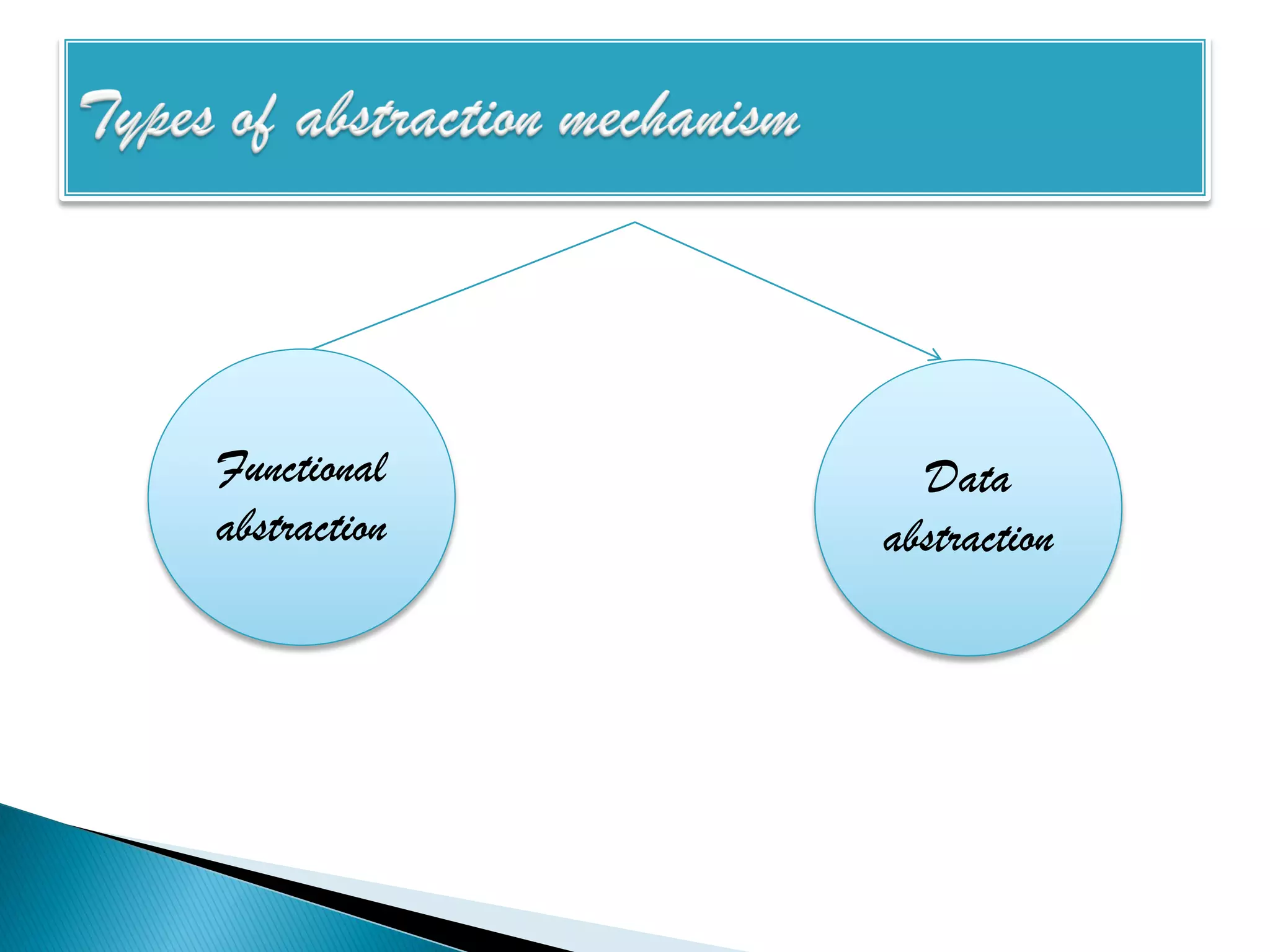
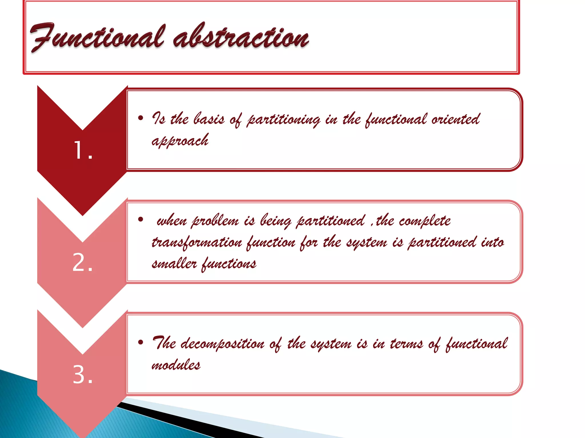
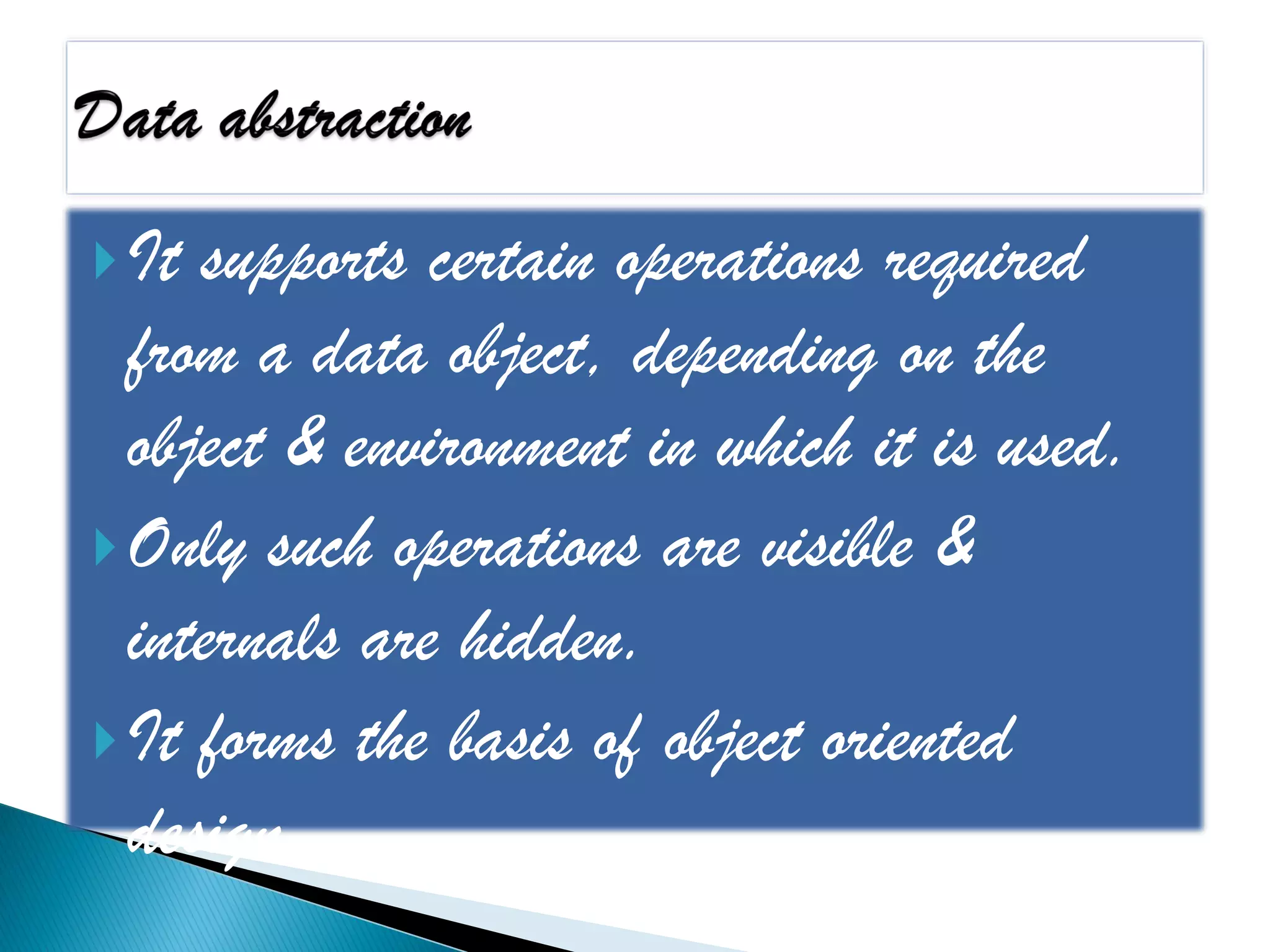
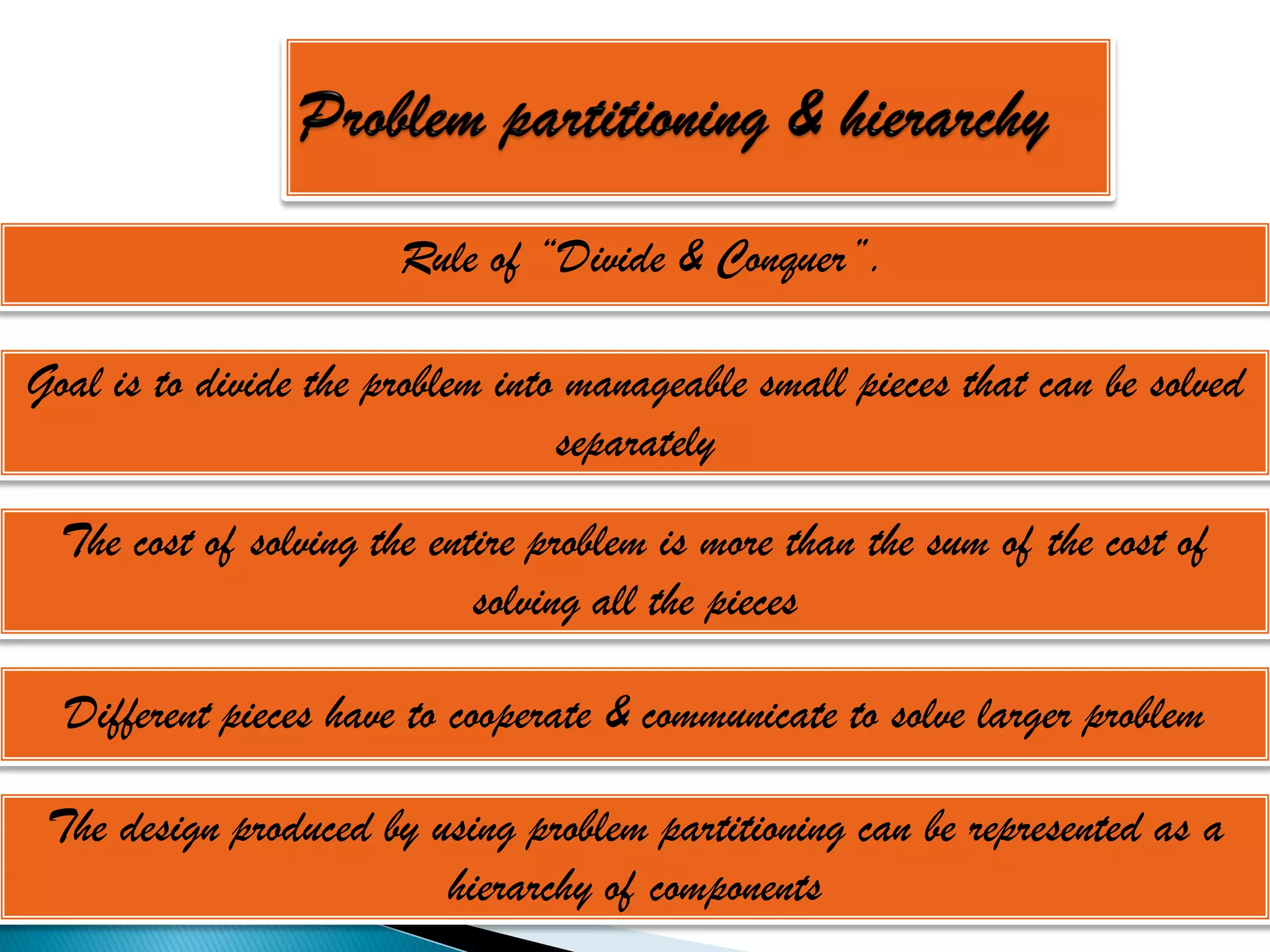
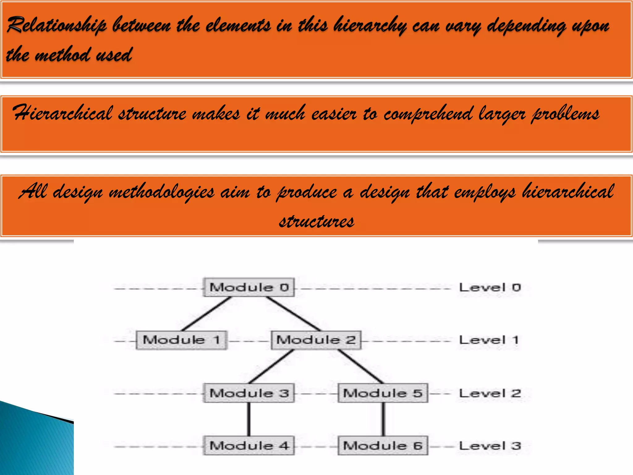
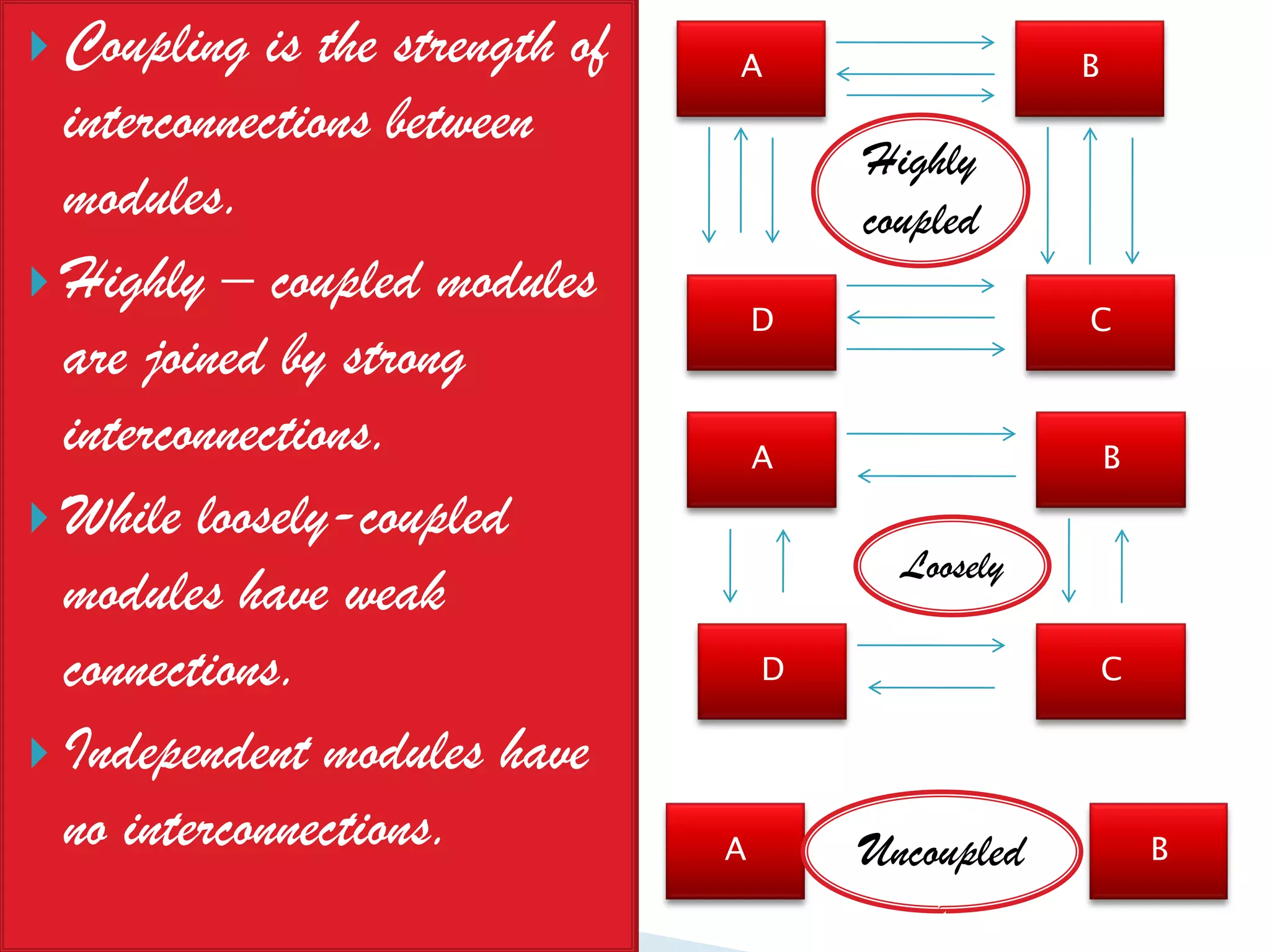
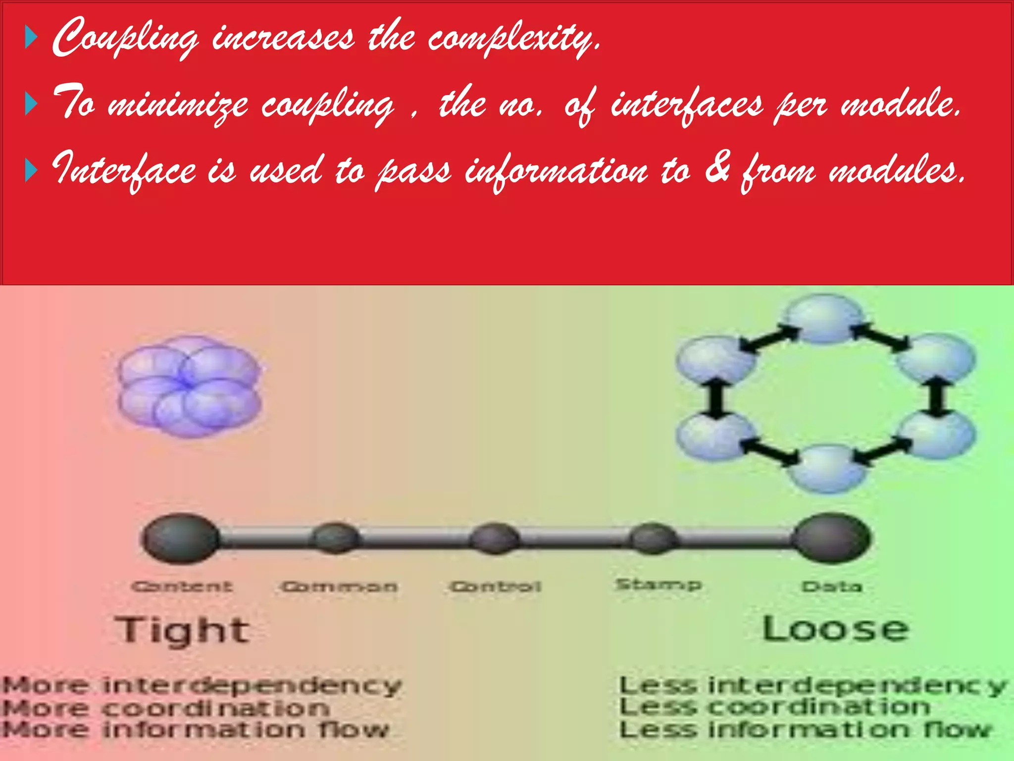
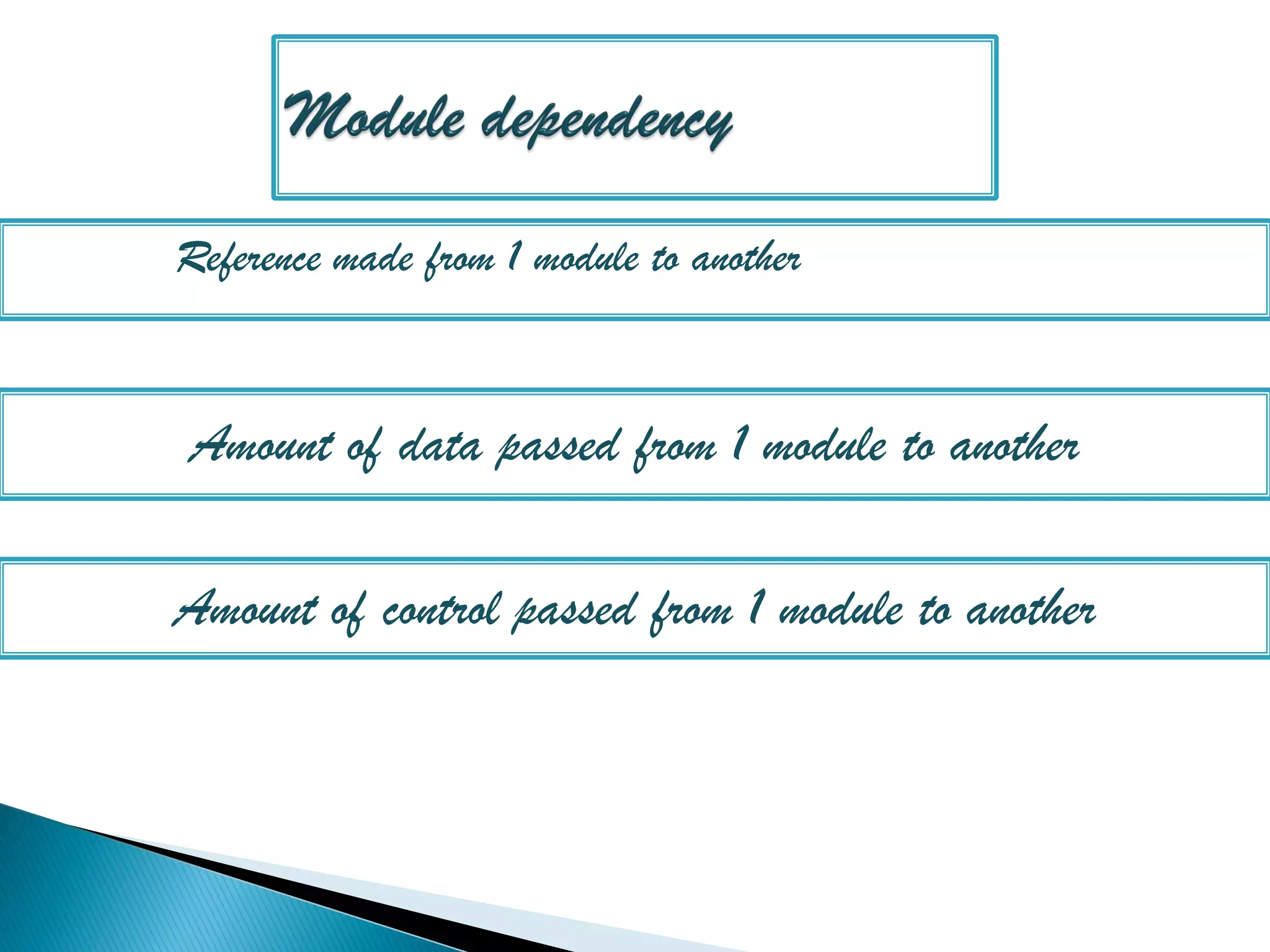
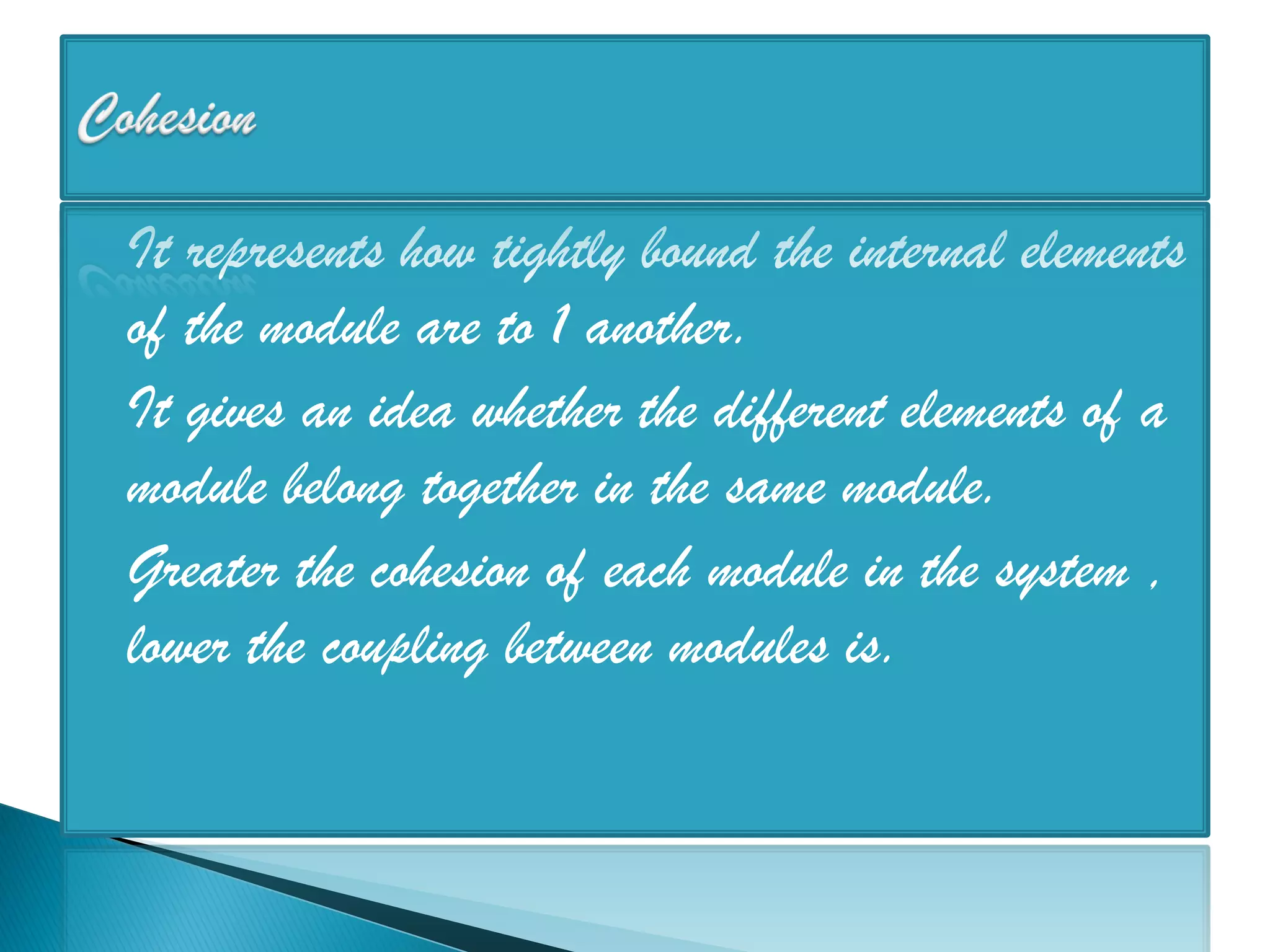
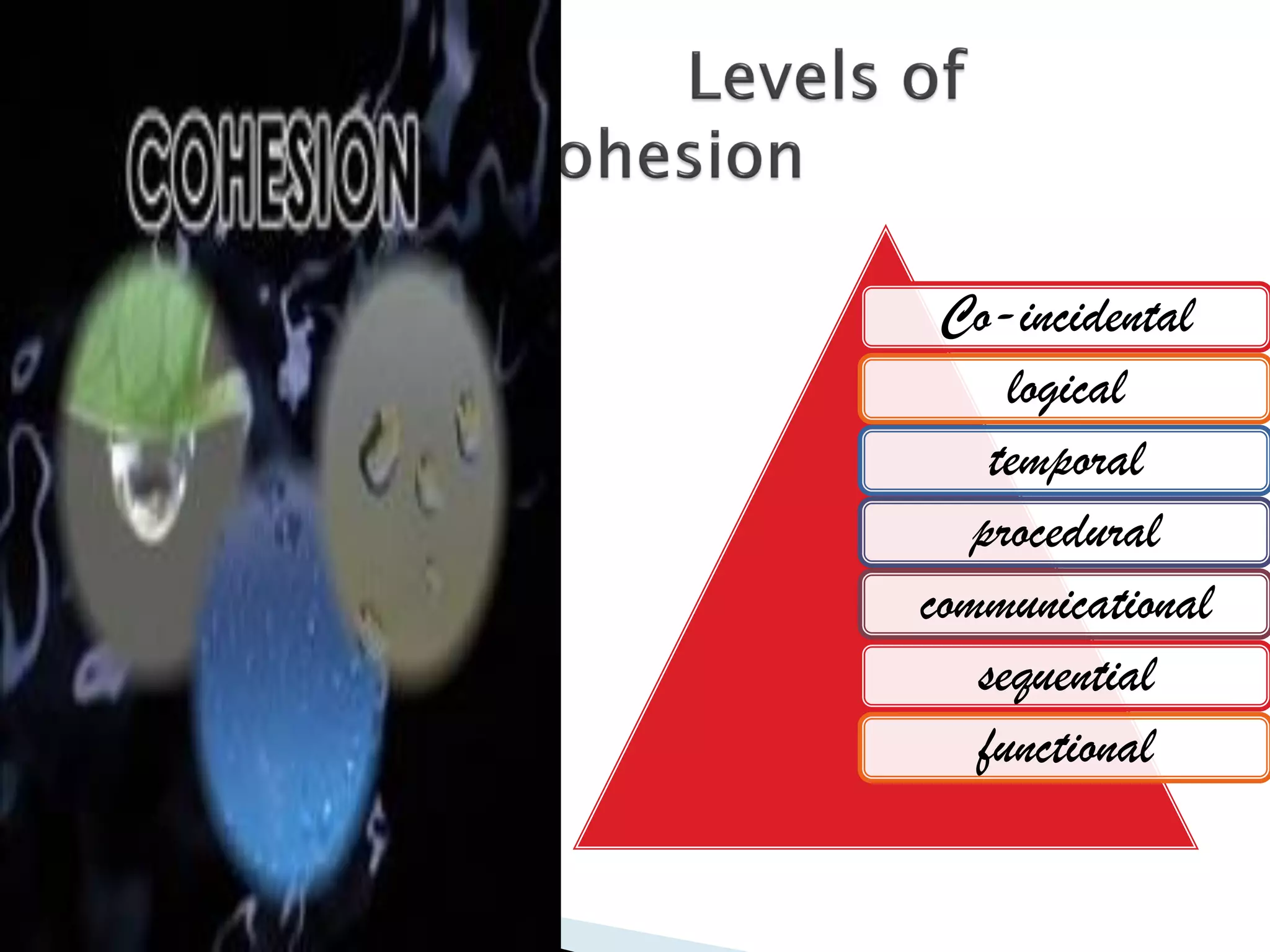
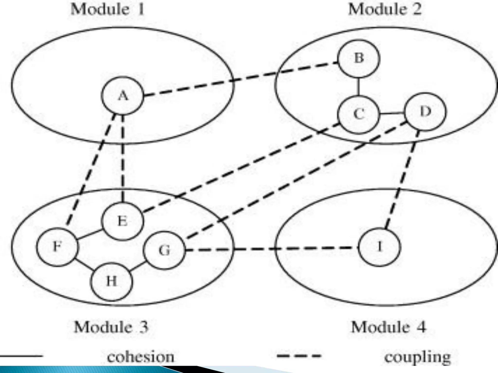
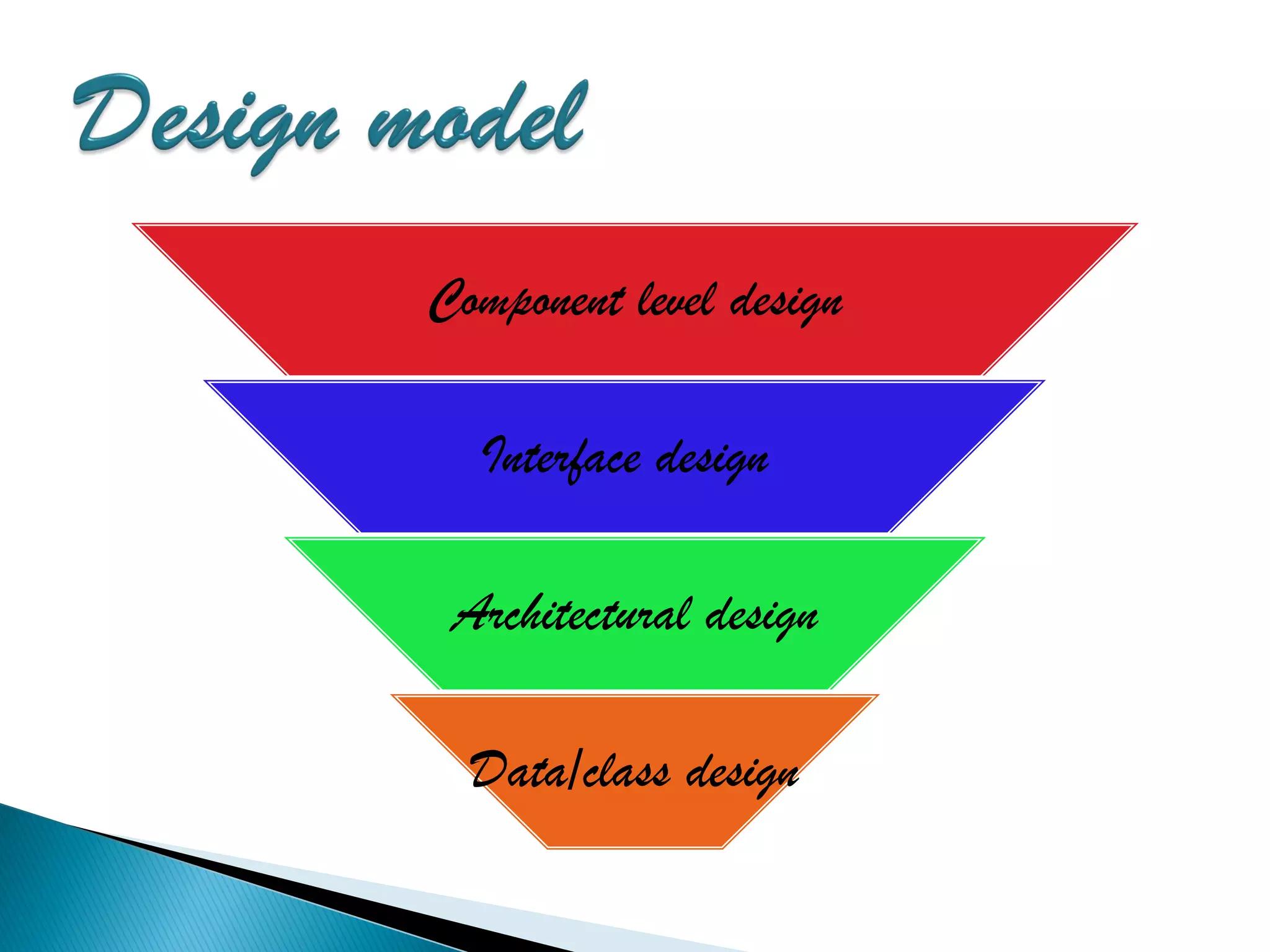
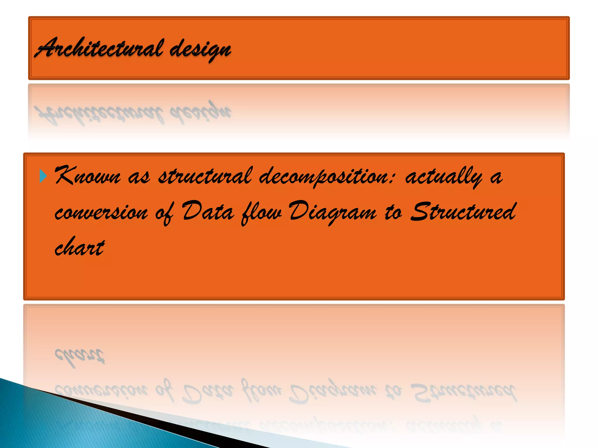
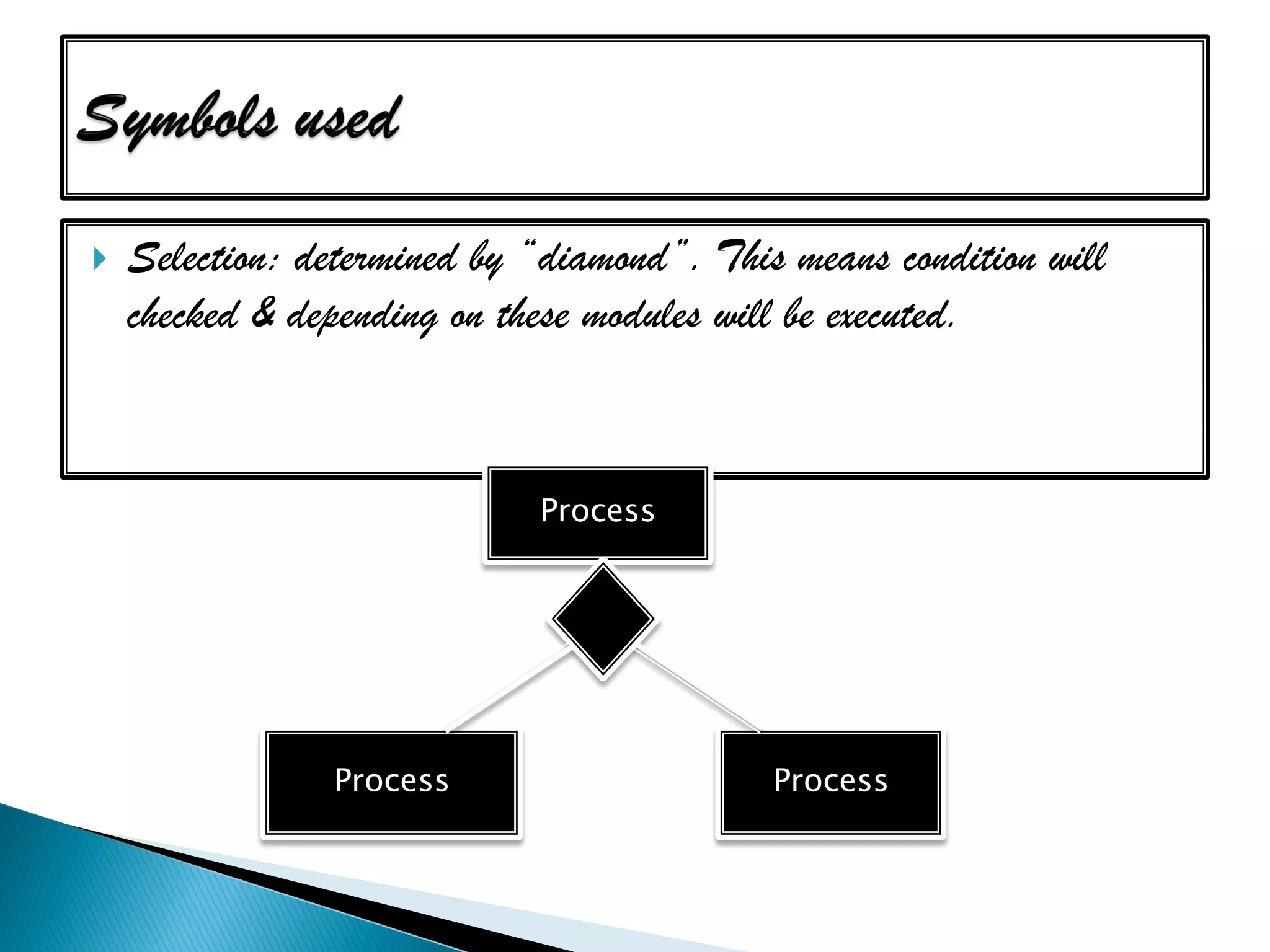
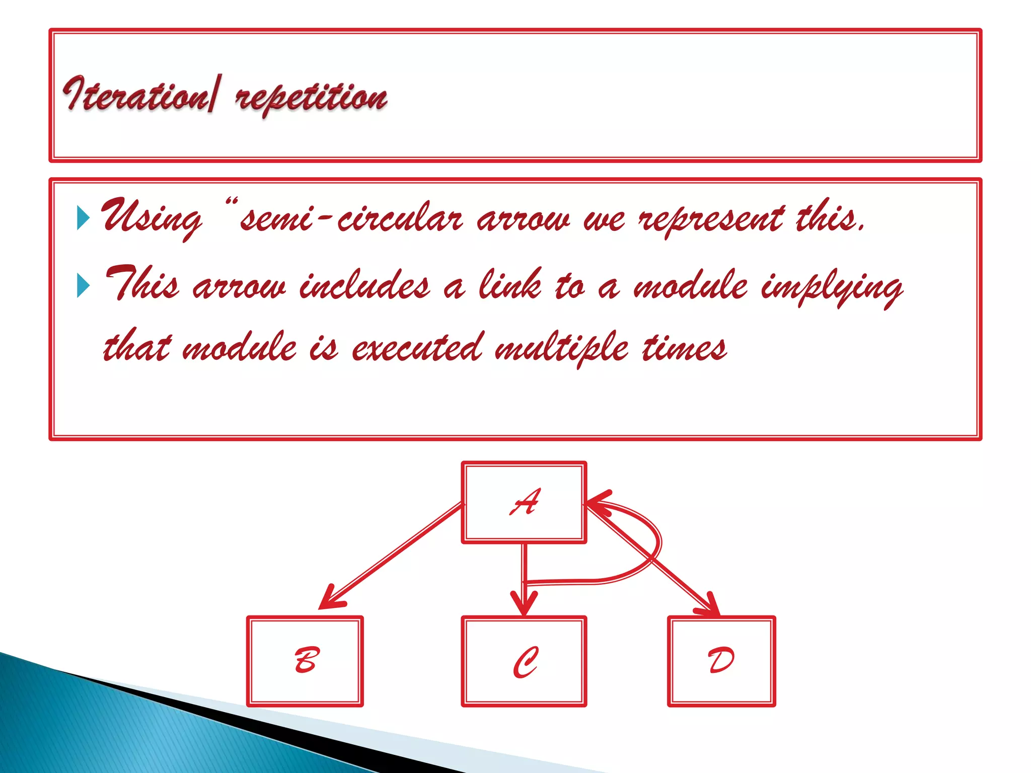
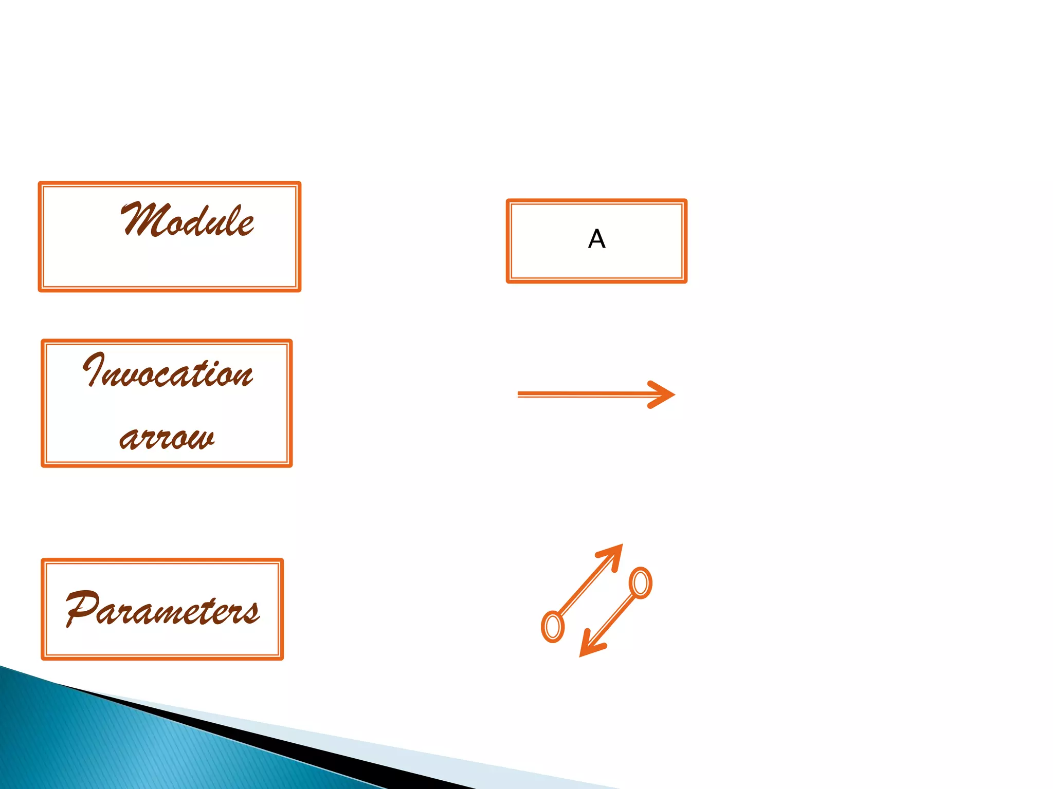
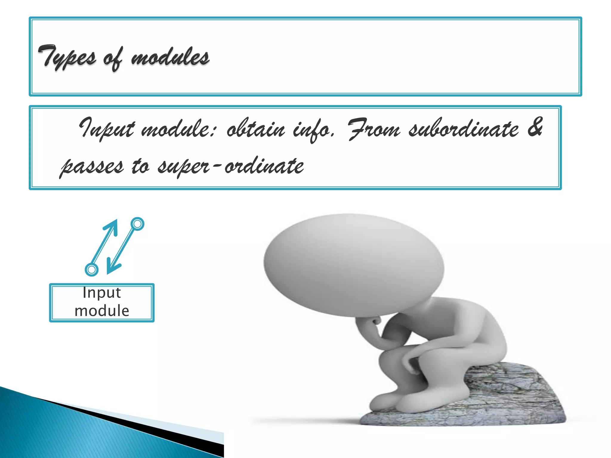
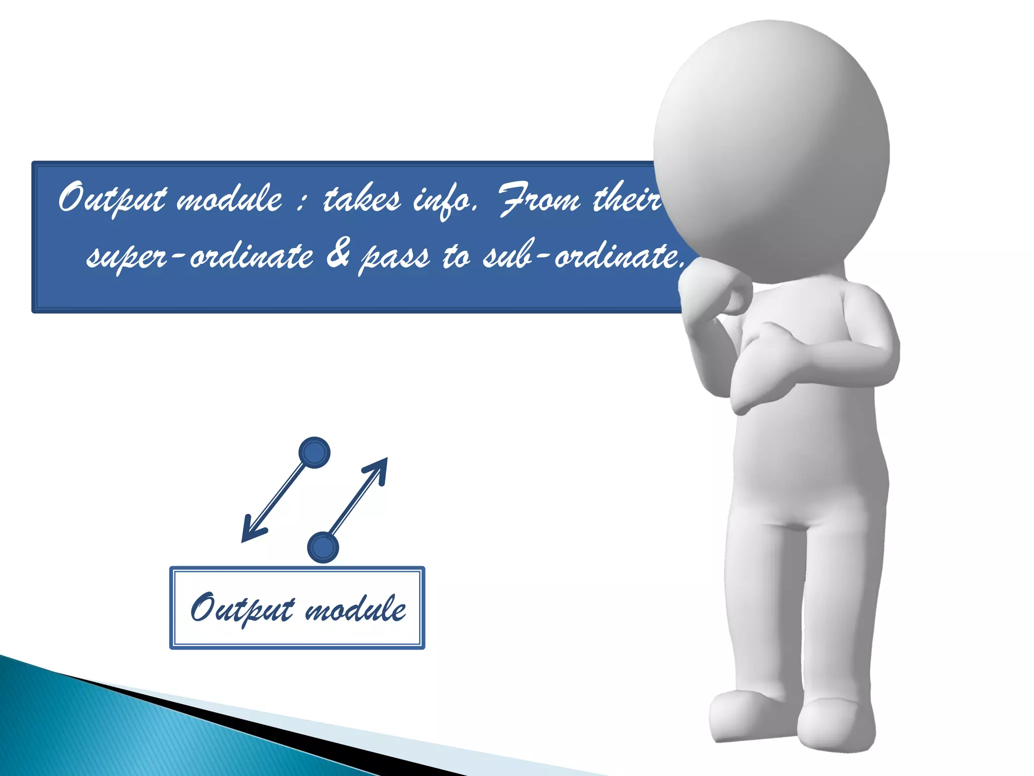
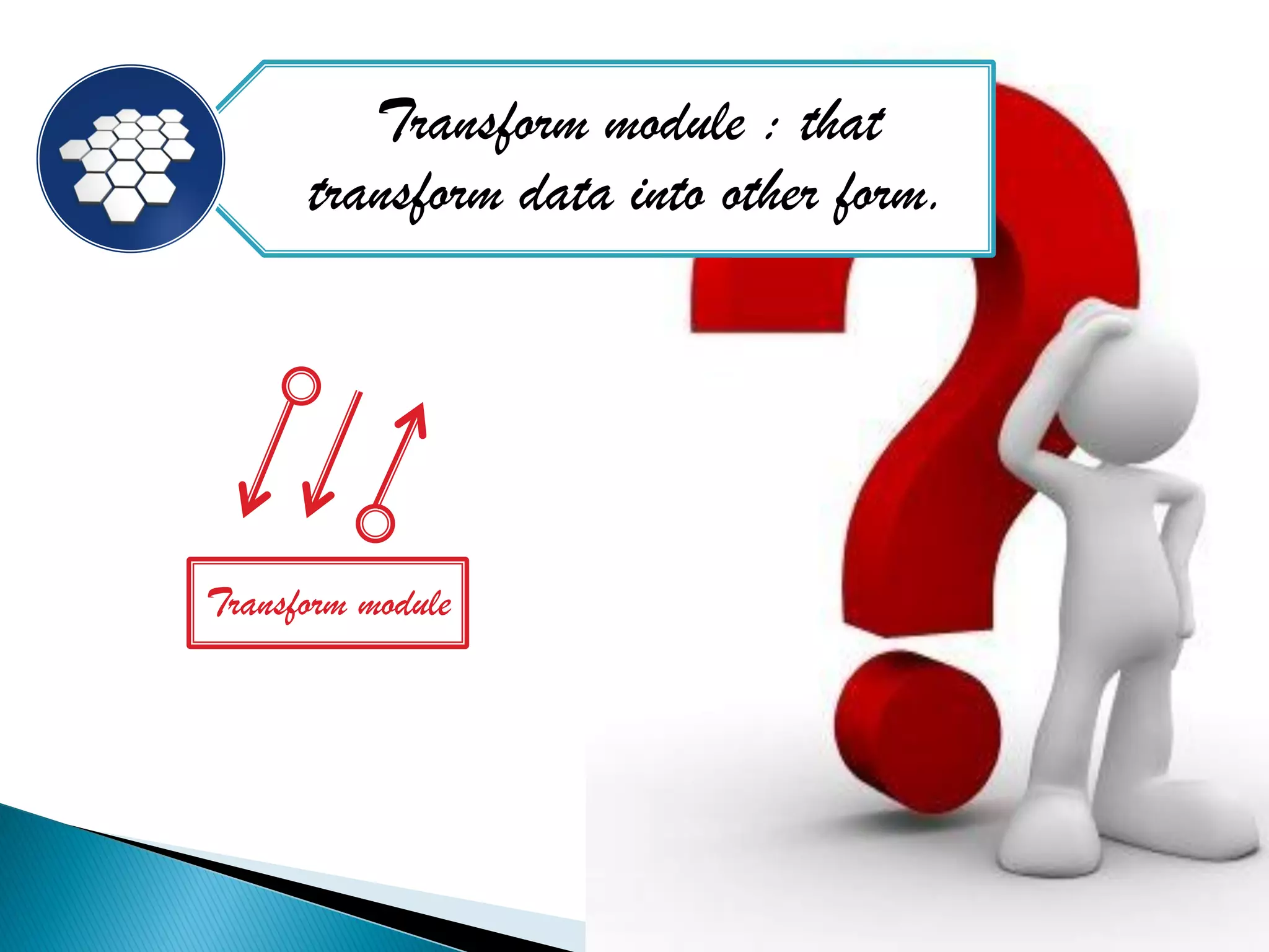
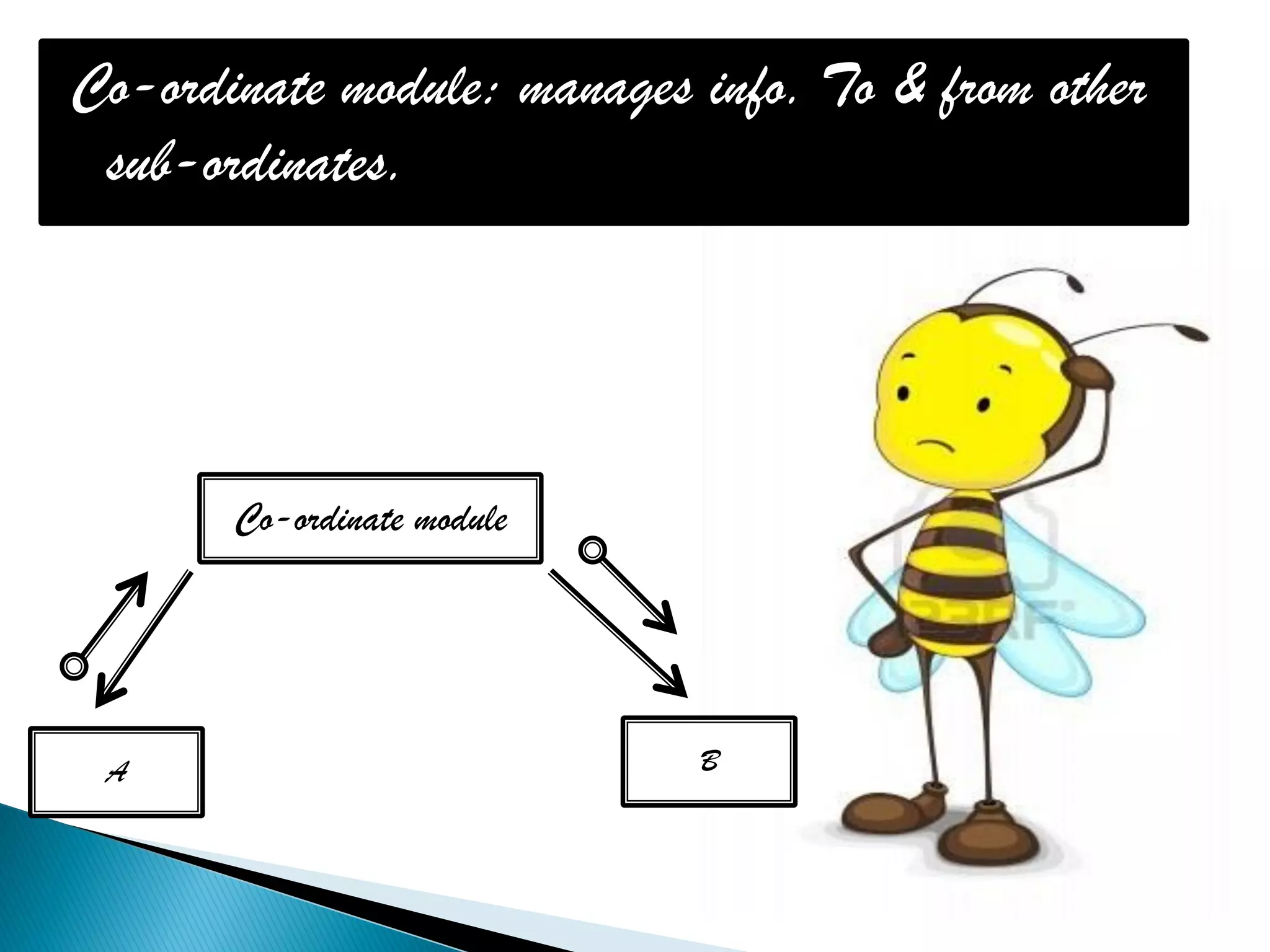
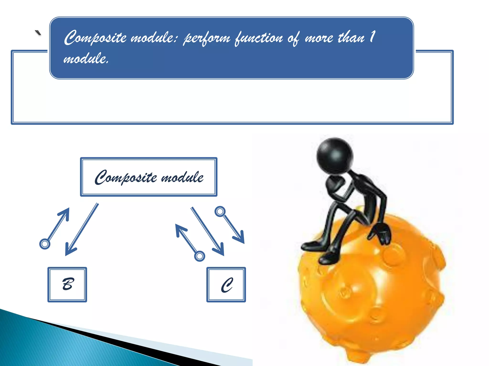
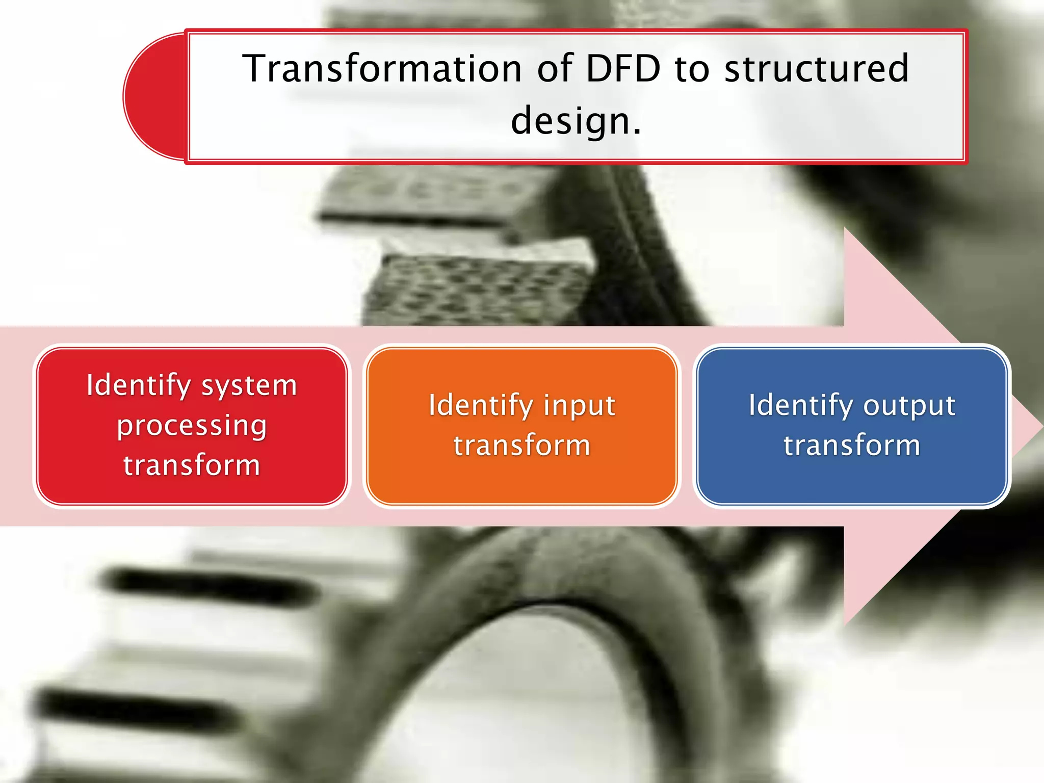
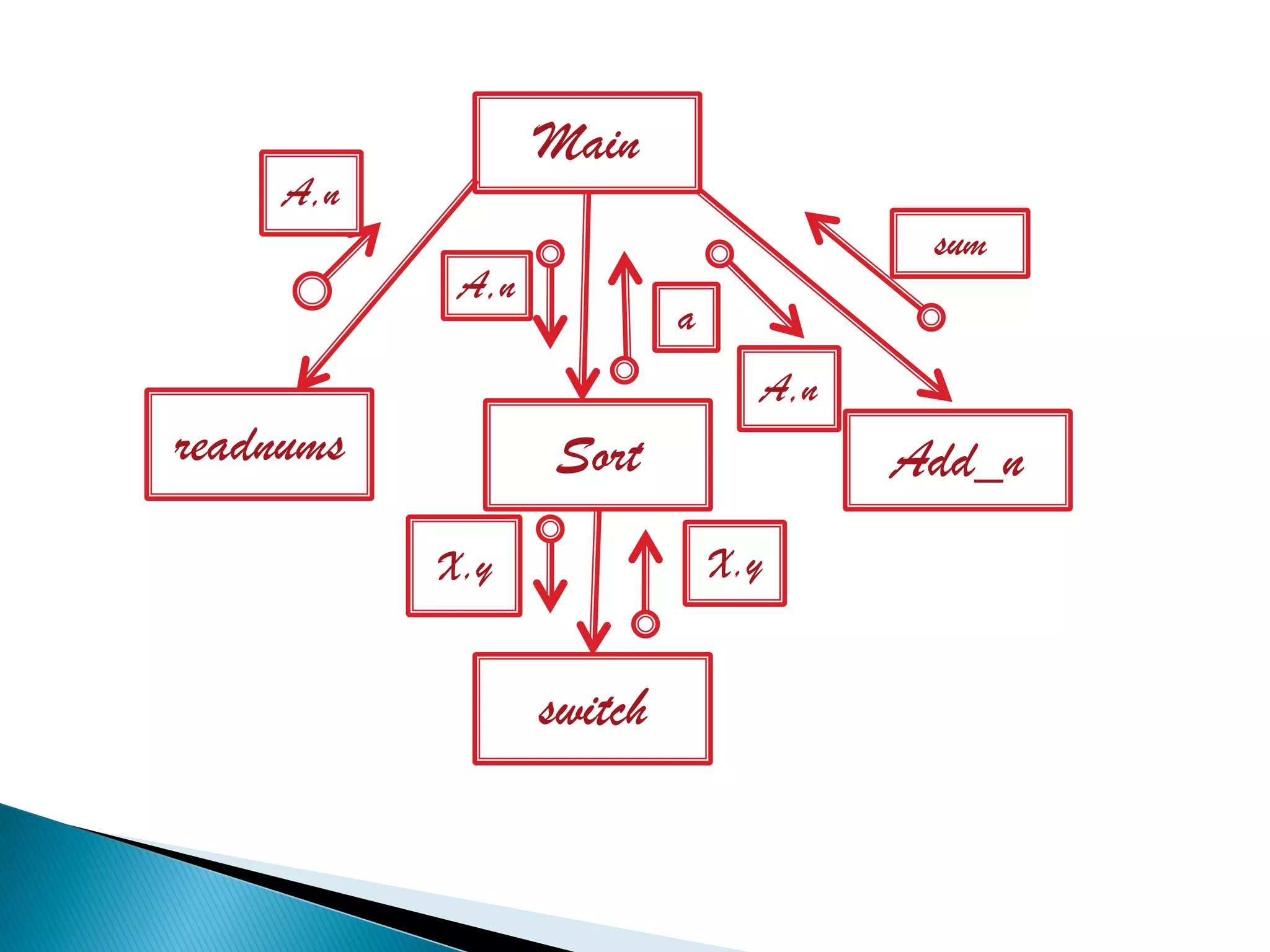
Guide:
Er. Deepinder Kaur
                     Presented By:
                     Sonali
                     Nikhil
                     Pallavi
Computer software, or
  just software, is a
  collection of computer
  programs and related
  data that provides the
  instructions for
  telling a computer
  what to do and how to
  do it.
Software is a set of
  programs, procedures,
  algorithms and its
  documentation
  concerned with the
  operation of a data
  processing system.
System Development Life Cycle
We are going to
study about the
 design phase.
Design elements describe the desired
       software features in detail


  These design elements are intended to
 describe the software in sufficient detail.

The focus of this process is to cover the gap
between understanding the specification and
     implementing them in the software

 Design process takes inputs of software
specifications and is dedicated to plan for
      implementation of the software.
Design Phase


Structured                  Structured
Analysis                      design
Structured analysis
   Structured Analysis (SA) in
    software engineering and its
    allied technique, Structured
    Design (SD), are methods for
    analyzing and converting
    business requirements into
    specifications and ultimately,
    computer programs, hardware
    configurations and related
    manual procedures.
Scenario based


Behavioral   Analysis model
                              Flow oriented based


              Class based
To describe customer
requirement

To establish basis of
design
 A data flow diagram (DFD)
  is a graphical representation of
  the "flow" of data through an
  information system, modeling
  its process aspects.
 A DFD shows what kinds of
  information will be input to and
  output from the system, where
  the data will come from and go
  to, and where the data will be
  stored.
Synchronous           Asynchronous
       operations            operations


                          If data goes to a
If data is going from 1
                          data store then to
   bubble to another
                             other bubble
Level 0    P
           0      Balancing
                   DFD’s

          P1
Level 1
          0.1

           P11         P12
Level 2   0.1.1       0.1.2
   Also known as “high – level design”
   Software architecture is made with the help of
    structured charts
Characteristics of Software Design

Correctness


Understandability


Efficiency


Maintainability
Process                                 Outcome

Identify nature of             Requirement
  requirement.                 specification

   Analysis & build                Functional
       modal                      specification
                                     system
                                   Mismatch b/w
      Validate solution            modal & design
                                    are removed

      Refine design solution         Design blueprint

           Implement design                Software
               solution                   architecture
cohesion

      abstraction               coupling


                    Concepts          Problem
modularity                           partitioning
                    of design        & hierarchy
Modularity


Concept of keeping
separate the various
unrevealed aspects
                            A
of a system so that
each aspect can be
studied in isolation.   B       C
It helps in system debugging.

In system repairs.

In system building.
Condition must for
  modularity!!

Each module needs
to support a well-
defined abstraction &
have a clear interface
through which it can
interact with other
modules.
Decomposition
Is creating lower level elements from higher lever key element
             on the basis of functions & features.
          Result of this is called MODULES.
 Abstraction  of a component describes the
  external behaviour of that component without
  bothering with the internal details that produce
  the behaviour
 It is essential for problem partitioning.
Functional      Data
abstraction   abstraction
• Is the basis of partitioning in the functional oriented
       approach
1.

     • when problem is being partitioned ,the complete
       transformation function for the system is partitioned into
2.     smaller functions


     • The decomposition of the system is in terms of functional
       modules
3.
 It supports certain operations required
  from a data object, depending on the
  object & environment in which it is used.
 Only such operations are visible &
  internals are hidden.
 It forms the basis of object oriented
  design.
Rule of “Divide & Conquer”.

Goal is to divide the problem into manageable small pieces that can be solved
                                  separately

  The cost of solving the entire problem is more than the sum of the cost of
                             solving all the pieces

  Different pieces have to cooperate & communicate to solve larger problem

 The design produced by using problem partitioning can be represented as a
                         hierarchy of components
Hierarchical structure makes it much easier to comprehend larger problems


All design methodologies aim to produce a design that employs hierarchical
                                structures
 Fan-in   refers to no. of units that use
  a particular software unit.
 Fan-out refers to no. of units used by
  particular software unit
Fan-in for B
  is 1 & fan-          Super-ordinate
                         of B & C
    out is 2
                                                A
       Sub-ordinate of A
       & super-ordinate of
           D,E&F                        B           C

Sub-ordinate of B
      &C                     D              E       F
 Two  modules are considered independent if one can
  function completely without the presence of other.
 The more connections between the modules ,the more they
  are dependent.
 Hence, fewer & simpler the connections between modules
  the easier is to understand them.
 Coupling   is the strength of   A                   B
  interconnections between
                                          Highly
  modules.                                coupled
 Highly – coupled modules
                                      D               C
  are joined by strong
  interconnections.                   A                   B

 While loosely-coupled
                                            Loosely
  modules have weak
  connections.                        D                   C

 Independent modules have
  no interconnections.            A       Uncoupled           B
 Coupling  increases the complexity.
 To minimize coupling , the no. of interfaces per module.
 Interface is used to pass information to & from modules.
Reference made from 1 module to another


Amount of data passed from 1 module to another

Amount of control passed from 1 module to another
 It represents how tightly bound the internal elements
  of the module are to 1 another.
 It gives an idea whether the different elements of a
  module belong together in the same module.
 Greater the cohesion of each module in the system ,
  lower the coupling between modules is.
Co-incidental
     logical
    temporal
   procedural
communicational
   sequential
   functional
Component level design

  Interface design

 Architectural design

  Data/class design
 Known  as structural decomposition: actually a
 conversion of Data flow Diagram to Structured
 chart
   Selection: determined by “diamond”. This means condition will
    checked & depending on these modules will be executed.


                             Process


                Process                     Process
 Using “semi-circular arrow we represent this.
 This arrow includes a link to a module implying
  that module is executed multiple times

                         A


            B            C           D
Module     A


Invocation
  arrow


Parameters
Input module: obtain info. From subordinate &
passes to super-ordinate


  Input
 module
Output module : takes info. From their
 super-ordinate & pass to sub-ordinate.


        Output module
Transform module : that
      transform data into other form.


Transform module
Co-ordinate module: manages info. To & from other
 sub-ordinates.


       Co-ordinate module


 A                          B
Composite module: perform function of more than 1
module.


    Composite module


B                       C
Transformation of DFD to structured
                        design.


Identify system
                    Identify input   Identify output
  processing
                      transform         transform
   transform
Main
     A,n
                                        sum
            A,n
                           a
                                 A,n
readnums          Sort                 Add_n
           X,y                 X,y


                  switch
Any questions
Thankyou you


   Made By :
   Sonali Narang
   B.Ca

Design1

  • 1.
    Guide: Er. Deepinder Kaur Presented By: Sonali Nikhil Pallavi
  • 3.
    Computer software, or just software, is a collection of computer programs and related data that provides the instructions for telling a computer what to do and how to do it. Software is a set of programs, procedures, algorithms and its documentation concerned with the operation of a data processing system.
  • 4.
  • 5.
    We are goingto study about the design phase.
  • 6.
    Design elements describethe desired software features in detail These design elements are intended to describe the software in sufficient detail. The focus of this process is to cover the gap between understanding the specification and implementing them in the software Design process takes inputs of software specifications and is dedicated to plan for implementation of the software.
  • 7.
    Design Phase Structured Structured Analysis design
  • 8.
    Structured analysis  Structured Analysis (SA) in software engineering and its allied technique, Structured Design (SD), are methods for analyzing and converting business requirements into specifications and ultimately, computer programs, hardware configurations and related manual procedures.
  • 9.
    Scenario based Behavioral Analysis model Flow oriented based Class based
  • 10.
    To describe customer requirement Toestablish basis of design
  • 11.
     A dataflow diagram (DFD) is a graphical representation of the "flow" of data through an information system, modeling its process aspects.  A DFD shows what kinds of information will be input to and output from the system, where the data will come from and go to, and where the data will be stored.
  • 12.
    Synchronous Asynchronous operations operations If data goes to a If data is going from 1 data store then to bubble to another other bubble
  • 13.
    Level 0 P 0 Balancing DFD’s P1 Level 1 0.1 P11 P12 Level 2 0.1.1 0.1.2
  • 14.
    Also known as “high – level design”  Software architecture is made with the help of structured charts
  • 15.
    Characteristics of SoftwareDesign Correctness Understandability Efficiency Maintainability
  • 16.
    Process Outcome Identify nature of Requirement requirement. specification Analysis & build Functional modal specification system Mismatch b/w Validate solution modal & design are removed Refine design solution Design blueprint Implement design Software solution architecture
  • 17.
    cohesion abstraction coupling Concepts Problem modularity partitioning of design & hierarchy
  • 18.
    Modularity Concept of keeping separatethe various unrevealed aspects A of a system so that each aspect can be studied in isolation. B C
  • 19.
    It helps insystem debugging. In system repairs. In system building.
  • 20.
    Condition must for modularity!! Each module needs to support a well- defined abstraction & have a clear interface through which it can interact with other modules.
  • 21.
    Decomposition Is creating lowerlevel elements from higher lever key element on the basis of functions & features. Result of this is called MODULES.
  • 22.
     Abstraction of a component describes the external behaviour of that component without bothering with the internal details that produce the behaviour  It is essential for problem partitioning.
  • 23.
    Functional Data abstraction abstraction
  • 24.
    • Is thebasis of partitioning in the functional oriented approach 1. • when problem is being partitioned ,the complete transformation function for the system is partitioned into 2. smaller functions • The decomposition of the system is in terms of functional modules 3.
  • 25.
     It supportscertain operations required from a data object, depending on the object & environment in which it is used.  Only such operations are visible & internals are hidden.  It forms the basis of object oriented design.
  • 26.
    Rule of “Divide& Conquer”. Goal is to divide the problem into manageable small pieces that can be solved separately The cost of solving the entire problem is more than the sum of the cost of solving all the pieces Different pieces have to cooperate & communicate to solve larger problem The design produced by using problem partitioning can be represented as a hierarchy of components
  • 27.
    Hierarchical structure makesit much easier to comprehend larger problems All design methodologies aim to produce a design that employs hierarchical structures
  • 28.
     Fan-in refers to no. of units that use a particular software unit.  Fan-out refers to no. of units used by particular software unit
  • 29.
    Fan-in for B is 1 & fan- Super-ordinate of B & C out is 2 A Sub-ordinate of A & super-ordinate of D,E&F B C Sub-ordinate of B &C D E F
  • 30.
     Two modules are considered independent if one can function completely without the presence of other.  The more connections between the modules ,the more they are dependent.  Hence, fewer & simpler the connections between modules the easier is to understand them.
  • 31.
     Coupling is the strength of A B interconnections between Highly modules. coupled  Highly – coupled modules D C are joined by strong interconnections. A B  While loosely-coupled Loosely modules have weak connections. D C  Independent modules have no interconnections. A Uncoupled B
  • 32.
     Coupling increases the complexity.  To minimize coupling , the no. of interfaces per module.  Interface is used to pass information to & from modules.
  • 33.
    Reference made from1 module to another Amount of data passed from 1 module to another Amount of control passed from 1 module to another
  • 34.
     It representshow tightly bound the internal elements of the module are to 1 another.  It gives an idea whether the different elements of a module belong together in the same module.  Greater the cohesion of each module in the system , lower the coupling between modules is.
  • 35.
    Co-incidental logical temporal procedural communicational sequential functional
  • 37.
    Component level design Interface design Architectural design Data/class design
  • 38.
     Known as structural decomposition: actually a conversion of Data flow Diagram to Structured chart
  • 39.
    Selection: determined by “diamond”. This means condition will checked & depending on these modules will be executed. Process Process Process
  • 40.
     Using “semi-circulararrow we represent this.  This arrow includes a link to a module implying that module is executed multiple times A B C D
  • 41.
    Module A Invocation arrow Parameters
  • 42.
    Input module: obtaininfo. From subordinate & passes to super-ordinate Input module
  • 43.
    Output module :takes info. From their super-ordinate & pass to sub-ordinate. Output module
  • 44.
    Transform module :that transform data into other form. Transform module
  • 45.
    Co-ordinate module: managesinfo. To & from other sub-ordinates. Co-ordinate module A B
  • 46.
    Composite module: performfunction of more than 1 module. Composite module B C
  • 47.
    Transformation of DFDto structured design. Identify system Identify input Identify output processing transform transform transform
  • 48.
    Main A,n sum A,n a A,n readnums Sort Add_n X,y X,y switch
  • 49.
  • 50.
    Thankyou you Made By : Sonali Narang B.Ca