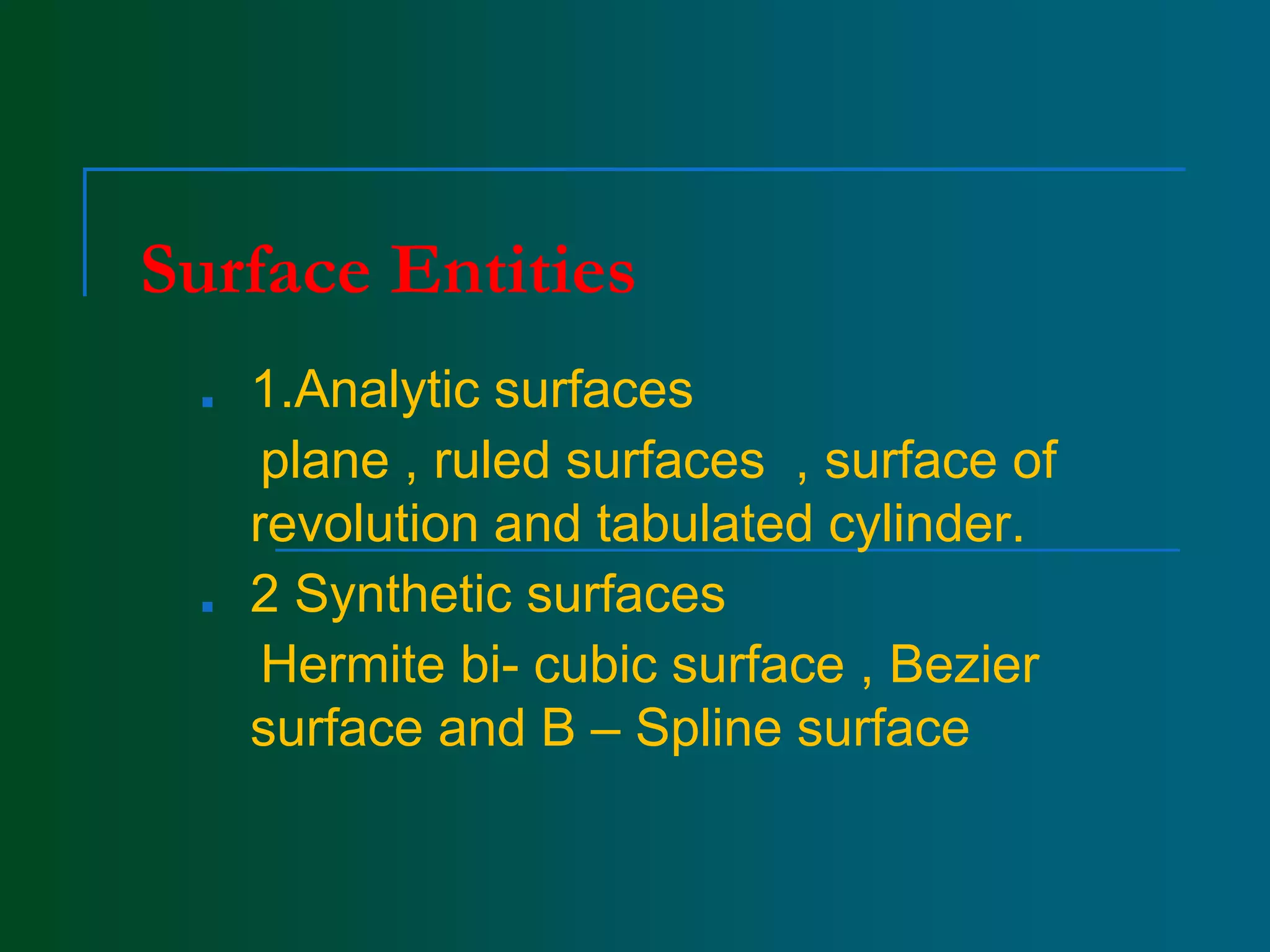
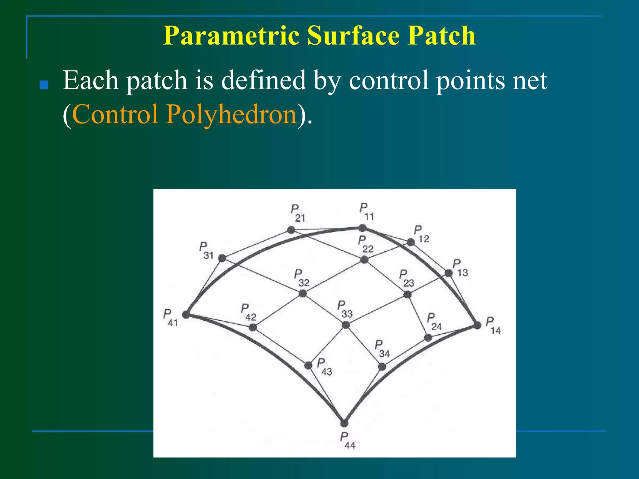
Surface Modelling
Parametric Surfaces
■ Wire frame modelling are unable to represent complex surfaces
of objects like car , ship, airplane wing, castings but surface
model can used to represent the surface profile of these objects
■ surface model can be used for calculating mass properties ,
and interference between parts for generating view and finite
elements mesh and NC tool paths for continuous path
machining
■ This model used for fitting experimental data , discretised
solutions of differential equations, construction of pressure
surfaces , construction of stress distribution.
■ This surface of object is a more complete and less ambiguous
than the wire frame modeling
Surface Entities
■ 1.Analytic surfaces
plane , ruled surfaces , surface of
revolution and tabulated cylinder.
■ 2 Synthetic surfaces
Hermite bi- cubic surface , Bezier
surface and B – Spline surface
Surface Modeling
■ There are two types of surfaces that are
commonly used in modeling systems,
parametric and implicit.
■ Implicit Surface: It is defined by a polynomial
of three variables :f ( x ,y , z )=0
■ Example: (x-x0)2+(y-y0)2+(z-z0)2-r2=0
■ 8 X 2- X Y 2 + X Z 2 + Y 2 + Z 2 – 8 = 0
■ Surfaces which have polynomial (implicit)
forms are called algebraic surfaces
Parametric Surfaces
■ Parametric surfaces are defined by a set of three functions,
one for each coordinate
x=f(u,v), y=f(u,v), z=f(u,v)
■ Where u and v are in certain domain in the range of 0 and 1 .
■ Thus (u , v ) is a point in the square defined by (0,0)
(1,0) ,(0,1) and (1,1)in the uv – coordinate plane.
■ Parametric surfaces :
f(u,v) = ( x(u,v), y(u,v), z(u,v) )
■ Assume both u and v are in the range of 0 and 1.
Parametric Surfaces
■ Parametric surfaces or more precisely parametric surface
patches are not used individually.
■ Many parametric surface patches are joined together side-by-
side to form a more complicated shape.
Patch
Parametric Surface Patch
■ Each patch is defined by control points net
(Control Polyhedron).
Parametric Surface Patch
■ A parametric surface patch can be considered as a union of
(infinite number) of curves.
■ Given a parametric surface f(u,v), if u is fixed to a value, and let v
vary, this generates a curve on the surface whose u coordinate is a
constant. This is the isoparametric curve in the v direction.
■ Similarly, fixing v to a value and letting u vary, we obtain an
isoparametric curve whose v direction is a constant.
Parametric Surface Patch
■ Point Q(u,v) on the patch is the tensor product
of parametric curves defined by the control
points.
Surface Patch
■ The effect of “lifting” one of he control points of
a patch.
Quadric surfaces in normal forms
Quadric surfaces in general form
■ It has ten co-efficients
Parametric representation of Analytic surfaces
p
1. Plane surface :
■ This is the simplest surface and requires three
non – coincidental points to define an infinite
plane
■ The plane surface can be used to generate cross –
sectional views by intersecting a surface with it.
2. Ruled (lofted) surface: This is linear surface ,interpolates
linearly b/w two boundary curves that define the surface.
Boundary curves can be in the form of any wireframe entity
3. Surface of Revolution
This is an axisymmetric surface that can be model axisymmetric objects.
It is generated by a planar wire frame entity in space about the axis of symmetry
of a given angle
Line AB is rotated abt the z- axis through an angle of 1800 generating
cylinder.
Any point on the surface is a function of two parameters U and ɵ
u describes the entity to be rotated and ɵ represent the angle of
rotation .In general form
P(u , v)= r (u) cos ɵ + r(u) sin ɵ + z(u ) n3
•4.Tabulated cylinder:
1.This is surface by translating a plane curve at a given distance
along a specified direction.
2.Plane of the curve is perpendicular to the axis of generated cylinder
Surface modelling

Surface modelling

  • 1.
    Surface Modelling Parametric Surfaces ■Wire frame modelling are unable to represent complex surfaces of objects like car , ship, airplane wing, castings but surface model can used to represent the surface profile of these objects ■ surface model can be used for calculating mass properties , and interference between parts for generating view and finite elements mesh and NC tool paths for continuous path machining ■ This model used for fitting experimental data , discretised solutions of differential equations, construction of pressure surfaces , construction of stress distribution. ■ This surface of object is a more complete and less ambiguous than the wire frame modeling
  • 3.
    Surface Entities ■ 1.Analyticsurfaces plane , ruled surfaces , surface of revolution and tabulated cylinder. ■ 2 Synthetic surfaces Hermite bi- cubic surface , Bezier surface and B – Spline surface
  • 4.
    Surface Modeling ■ Thereare two types of surfaces that are commonly used in modeling systems, parametric and implicit. ■ Implicit Surface: It is defined by a polynomial of three variables :f ( x ,y , z )=0 ■ Example: (x-x0)2+(y-y0)2+(z-z0)2-r2=0 ■ 8 X 2- X Y 2 + X Z 2 + Y 2 + Z 2 – 8 = 0 ■ Surfaces which have polynomial (implicit) forms are called algebraic surfaces
  • 5.
    Parametric Surfaces ■ Parametricsurfaces are defined by a set of three functions, one for each coordinate x=f(u,v), y=f(u,v), z=f(u,v) ■ Where u and v are in certain domain in the range of 0 and 1 . ■ Thus (u , v ) is a point in the square defined by (0,0) (1,0) ,(0,1) and (1,1)in the uv – coordinate plane.
  • 6.
    ■ Parametric surfaces: f(u,v) = ( x(u,v), y(u,v), z(u,v) ) ■ Assume both u and v are in the range of 0 and 1.
  • 7.
    Parametric Surfaces ■ Parametricsurfaces or more precisely parametric surface patches are not used individually. ■ Many parametric surface patches are joined together side-by- side to form a more complicated shape. Patch
  • 8.
    Parametric Surface Patch ■Each patch is defined by control points net (Control Polyhedron).
  • 9.
    Parametric Surface Patch ■A parametric surface patch can be considered as a union of (infinite number) of curves. ■ Given a parametric surface f(u,v), if u is fixed to a value, and let v vary, this generates a curve on the surface whose u coordinate is a constant. This is the isoparametric curve in the v direction. ■ Similarly, fixing v to a value and letting u vary, we obtain an isoparametric curve whose v direction is a constant.
  • 10.
    Parametric Surface Patch ■Point Q(u,v) on the patch is the tensor product of parametric curves defined by the control points.
  • 11.
    Surface Patch ■ Theeffect of “lifting” one of he control points of a patch.
  • 12.
    Quadric surfaces innormal forms
  • 17.
    Quadric surfaces ingeneral form ■ It has ten co-efficients
  • 18.
    Parametric representation ofAnalytic surfaces p 1. Plane surface : ■ This is the simplest surface and requires three non – coincidental points to define an infinite plane ■ The plane surface can be used to generate cross – sectional views by intersecting a surface with it.
  • 21.
    2. Ruled (lofted)surface: This is linear surface ,interpolates linearly b/w two boundary curves that define the surface. Boundary curves can be in the form of any wireframe entity
  • 23.
    3. Surface ofRevolution This is an axisymmetric surface that can be model axisymmetric objects. It is generated by a planar wire frame entity in space about the axis of symmetry of a given angle
  • 24.
    Line AB isrotated abt the z- axis through an angle of 1800 generating cylinder. Any point on the surface is a function of two parameters U and ɵ u describes the entity to be rotated and ɵ represent the angle of rotation .In general form P(u , v)= r (u) cos ɵ + r(u) sin ɵ + z(u ) n3
  • 25.
    •4.Tabulated cylinder: 1.This issurface by translating a plane curve at a given distance along a specified direction. 2.Plane of the curve is perpendicular to the axis of generated cylinder