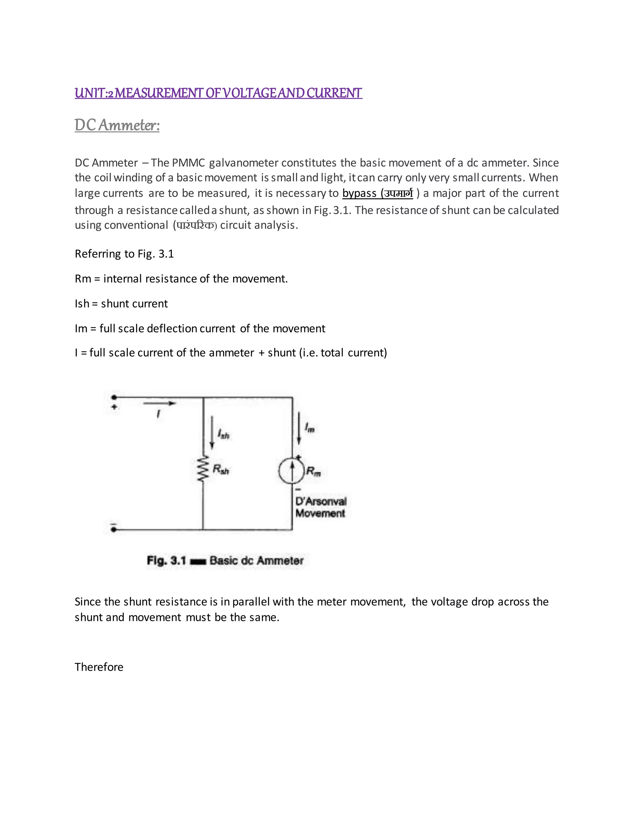
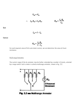
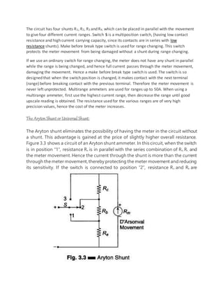
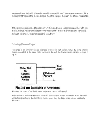
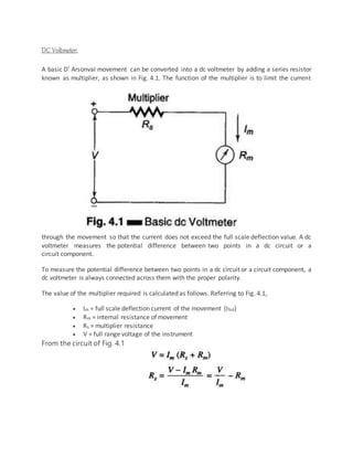
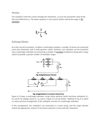
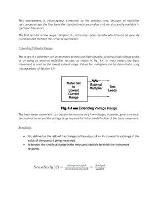
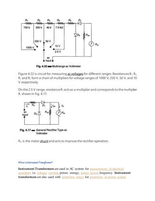
UNIT:2MEASUREMENT OFVOLTAGEANDCURRENT
DC Ammeter:
DC Ammeter – The PMMC galvanometer constitutes the basic movement of a dc ammeter. Since
the coilwinding of a basicmovement is smalland light, itcan carry only very smallcurrents. When
large currents are to be measured, it is necessary to bypass (उपमार्ग ) a major part of the current
through a resistancecalledashunt, as shown in Fig.3.1. The resistanceof shunt can be calculated
using conventional (पारंपररक) circuit analysis.
Referring to Fig. 3.1
Rm = internal resistance of the movement.
Ish = shunt current
Im = full scale deflection current of the movement
I = full scale current of the ammeter + shunt (i.e. total current)
Since the shunt resistance is in parallel with the meter movement, the voltage drop across the
shunt and movement must be the same.
Therefore
For each required value of full scale meter current, we can determine the value of shunt
resistance.
Multi rangeAmmeters:
The current range of the dc ammeter may be further extended by a number of shunts, selected
by a range switch. Such a meter is called a multirange ammeter, shown in Fig. 3.2.
The circuit has four shunts R1, R2, R3 and R4, which can be placed in parallel with the movement
to give four different current ranges. Switch S is a multiposition switch, (having low contact
resistance and high current carrying capacity, since its contacts are in series with low
resistance shunts). Make before break type switch is used for range changing. This switch
protects the meter movement from being damaged without a shunt during range changing.
If we use an ordinary switch for range changing, the meter does not have any shunt in parallel
while the range is being changed, and hence full current passes through the meter movement,
damaging the movement. Hence a make before break type switch is used. The switch is so
designed that when the switch position is changed, it makes contact with the next terminal
(range) before breaking contact with the previous terminal. Therefore the meter movement is
never left unprotected. Multirange ammeters are used for ranges up to 50A. When using a
multirange ammeter, first use the highest current range, then decrease the range until good
upscale reading is obtained. The resistance used for the various ranges are of very high
precision values, hence the cost of the meter increases.
The Aryton Shunt or Universal Shunt:
The Aryton shunt eliminates the possibility of having the meter in the circuit without
a shunt. This advantage is gained at the price of slightly higher overall resistance.
Figure 3.3 shows a circuit of an Aryton shunt ammeter. In this circuit, when the switch
is in position “1”, resistance Ra is in parallel with the series combination of Rb, Rc, and
the meter movement. Hence the current through the shunt is more than the current
through the meter movement,thereby protecting the meter movement and reducing
its sensitivity. If the switch is connected to position “2”, resistance Ra and Rb are
together in parallel with the series combinationof Rc and the meter movement. Now
the current through the meter is more than the current through the shunt resistance.
If the switch is connected to position “3” Ra, Rb and Rc are together in parallel with the
meter. Hence, maximum current flows through the meter movementand very little
through the shunt. This increases the sensitivity.
Extendingof Ammeter Ranges:
The range of an ammeter can be extended to measure high current values by using external
shunts connected to the basic meter movement (usually the lowest current range), as given in
Fig. 3.5.
Note that the range of the basic meter movement cannot be lowered.
(For example, if a 100 μA movement with 100 scale division is used to measure 1 μA, the meter
will deflect by only one division. Hence ranges lower than the basic range are not practically
possible.)
DC Voltmeter:
A basic D’ Arsonval movement can be converted into a dc voltmeter by adding a series resistor
known as multiplier, as shown in Fig. 4.1. The function of the multiplier is to limit the current
through the movement so that the current does not exceed the full scale deflection value. A dc
voltmeter measures the potential difference between two points in a dc circuit or a
circuit component.
To measure the potential difference between two points in a dc circuit or a circuit component, a
dc voltmeter is always connected across them with the proper polarity.
The value of the multiplier required is calculated as follows. Referring to Fig. 4.1,
 Im = full scale deflection current of the movement (Ifsd)
 Rm = internal resistance of movement
 Rs = multiplier resistance
 V = full range voltage of the instrument
From the circuit of Fig. 4.1
Therefore
The multiplier limits the current through the movement, so as to not exceed the value of the
full scale deflection Ifsd. The above equation is also used to further extend the range in DC
voltmeter.
MultirangeVoltmeter:
As in the caseof an ammeter, to obtain a multirange ammeter, anumber of shunts are connected
across the movement with a multi-position switch. Similarly, a dc voltmeter can be converted
into a multirange voltmeter by connecting a number of resistors (multipliers) along with a range
switch to provide a greater number of workable ranges.
Figure 4.2 shows a multirange voltmeter using a three position switch and three multipliers R1,
R2, and R3 for voltage values V1, V2, and V3. Figure 4.2 can be further modified to Fig. 4.3, which
is a more practical arrangement of the multiplier resistors of a multirange voltmeter.
In this arrangement, the multipliers are connected in a series string, and the range selector
selects the appropriate amount of resistance required in series with the movement.
This arrangement is advantageous compared to the previous one, because all multiplier
resistances except the first have the standard resistance value and are also easily available in
precision tolerances:
The first resistor or low range multiplier, R4, is the only special resistor which has to be specially
manufactured to meet the circuit requirements.
ExtendingVoltmeter Ranges:
The range of a voltmeter canbe extended to measure high voltages,by using a high voltageprobe
or by using an external multiplier resistor, as shown in Fig. 4.4. In most meters the basic
movement is used on the lowest current range. Values for multipliers can be determined using
the procedure of Section 4.4.
The basic meter movement can be used to measure very low voltages. However, great care must
be used not to exceed the voltage drop required for full scale deflection of the basic movement.
Sensitivity:
 It is defined as the ratio of the changes in the output of an instrument to a change in the
value of the quantity being measured.
 It denotes the smallest change in the measured variable to which the instrument
responds.
 The sensitivity of an instrument is determined by dividing the sum of the resistance of
the meter (Rm) and the series resistance (Rs), by the full-scale reading in volts.
 Mathematically, sensitivity is expressed as
Expressing the above expression in units, we get:
Unit of instrument sensitivity is expressed in Ohm/Volt
Sensitivity is also expressed as:
So, sensitivity is said to be equal to the reciprocal of the full-scale deflection current
Loading Effect
When selecting a meter for a certain voltage measurement, it is important to consider the
sensitivity of a dc voltmeter. A low sensitivity meter may give a correct reading when measuring
voltages in a low resistance circuit, but it is certain to produce unreliable readings in a high
resistance circuit. A Voltmeter when connected across two points in a highly resistive circuits,
acts as a shunt for that portion of the circuit, reducing the total equivalent resistance of that
portion as shown in Fig. 4.6. The meter then indicates a lower reading than what existed before
the meter was connected. This is called the loading effect of an instrument and is caused mainly
by low sensitivity instruments.
AC Voltmeterusing Half wave Rectifier |ACVoltmeter using Fullwave Rectifier
The instrument, which is used to measure the AC voltage across any two points of
electric circuit is called AC voltmeter. If the AC voltmeter consists of rectifier, then it is
said to be rectifier based AC voltmeter.
The DC voltmeter measures only DC voltages. If we want to use it for measuring AC
voltages, then we have to follow these two steps.
 Step1 − Convert the AC voltage signal into a DC voltage signal by using a rectifier.
 Step2 − Measure the DC or average value of the rectifier’s output signal.
We get Rectifier based AC voltmeter, just by including the rectifier circuit to the basic
DC voltmeter. This chapter deals about rectifier based AC voltmeters.
Types of Rectifier based AC Voltmeters
Following are the two types of rectifier based AC voltmeters.
 AC voltmeter using Half Wave Rectifier
 AC voltmeter using Full Wave Rectifier
Now, let us discuss about these two AC voltmeters one by one.
AC Voltmeter using Half Wave Rectifier
If a Half wave rectifier is connected ahead of DC voltmeter, then that entire combination
together is called AC voltmeter using Half wave rectifier. The block diagram of AC
voltmeter using Half wave rectifier is shown in below figure.
The above block diagram consists of two blocks: half wave rectifier and DC voltmeter.
We will get the corresponding circuit diagram, just by replacing each block with the
respective component(s) in above block diagram. So, the circuit diagram of AC
voltmeter using Half wave rectifier will look like as shown in below figure
The rms value of sinusoidal (AC) input voltage signal is
Where,
Vm is the maximum value of sinusoidal (AC) input voltage signal.
The DC or average value of the Half wave rectifier’s output signal is
Substitute, the value of Vm in above equation.
Therefore, the AC voltmeter produces an output voltage, which is equal to 0.45 times the
rms value of the sinusoidal (AC) input voltage signal
AC Voltmeter using Full Wave Rectifier
If a Full wave rectifier is connected ahead of DC voltmeter, then that entire combination
together is called AC voltmeter using Full wave rectifier. The block diagram of AC
voltmeter using Full wave rectifier is shown in below figure
The above block diagram consists of two blocks: full wave rectifier and DC voltmeter.
We will get the corresponding circuit diagram just by replacing each block with the
respective component(s) in above block diagram.
So, the circuit diagram of AC voltmeter using Full wave rectifier will look like as shown
in below figure
The rms value of sinusoidal (AC) input voltage signal is
Where,
Vm is the maximum value of sinusoidal (AC) input voltage signal.
The DC or average value of the Full wave rectifier’s output signal is
Substitute, the value of Vm in above equation
Therefore, the AC voltmeter produces an output voltage, which is equal to 0.9 times the
rms value of the sinusoidal (AC) input voltage signal.
MultirangeACVoltmeter:
Figure 4.22 is circuit for measuring ac voltages for different ranges. Resistances R1, R2,
R3 and R4 form a chain of multipliers for voltage ranges of 1000 V, 250 V, 50 V, and 10
V respectively.
On the 2.5 V range, resistanceR5 acts as a multiplier and corresponds to the multiplier
Rs shown in Fig. 4.17.
Rsh is the meter shunt and acts to improve the rectifier operation.
What isInstrument Transformer?
Instrument Transformers are used in AC system for measurement of electrical
quantities i.e. voltage, current, power, energy, power factor, frequency. Instrument
transformers arealso used with protective relays for protection of power system
Types of Instrument Transformers
Instrument transformers are of two types –
1. Current Transformer (C.T.)
2. Potential Transformer (P.T).
1. CURRENTTRANSFORMERS
The current transformer is used with its primary winding connected in series with line
carrying the current to be measured and, therefore, the primary current is dependant
upon the load connected to the system and is not determined by the load (burden)
connected on the secondary winding of the current transformer. The primary
winding consists of very few turns and, therefore, there is no appreciable voltage
drop across it. The secondary winding of the current transformerhas larger number
of turns, the exact number being determined by the turns ratio. The ammeter,or
wattmeter currentcoil, are connected directly across the secondary winding
terminals. Thus a current transformeroperates its secondary winding nearly under
short circuit conditions. One of the terminals of the secondary winding is earthed so
as to protect equipment and personnel in the vicinity in the event of an insulation
breakdown in the current transformer. Figure (a) shows a circuit for measurementof
current and power with a current transformer.
Fig (a)
2. POTENTIALTRANSFORMERS
Potential transformers are used to operate voltmeters, the potential coils of wattmeters and
relays from high voltage lines. The primary winding of the transformer is connected across the
line carrying the voltage to be measured and the voltage circuit is connected across the
secondary winding.
The design of a potential transformer is quite similar to that of a power transformer but the
loading of a potential transformer is always small, sometimes only a few volt-ampere. The
secondary winding is designed so that a voltage of 100 to 120 V is delivered to the instrument
load. The normal secondary voltage rating is 110 V.
Difference betweenC.T. and P.T.
There are a few differences in the operation of a current transformer and a potential
transformer.
(i) The potential transformer may be considered as 'parallel' transformer with its secondary
winding operating nearly under open circuit conditions whereas the current transformer may
be thought as a 'series' transformer under virtual short circuit conditions. Thus the secondary
winding of a P.T. can be open circuited without any damage being caused either to the operator
or to the transformer.
(ii) The primary winding current in a C.T. is independent of the secondary winding circuit
conditions while the primary winding current in a P.T. certainly depends upon the secondary
circuit burden.
(iii) In a potential transformer, full line voltage is impressed upon its terminals whereas a C.T. is
connected in series with one line and a small voltage exists across its terminals. However, the
C.T. carries the full line current.
(iv) Under normal operation the line voltage is nearly constant and, therefore, the flux density
and hence the exciting current of a potential transformer varies only over a restricted range
whereas the primary winding current and excitation of a C.T. vary over wide limits in normal
operation.
ClamponAmmeters
A current transformer with a single conductor is used in combination with a bridge rectifier and
a d.c. milli-ammeter to produce a very useful service meter. The core of the transformer can be
split with the help of a trigger switch (Fig. (B)) and therefore the core can be clamped around a
live conductor to measure the current. Thus this arrangement avoids the necessity of breaking
the circuit in order that a current measuring device be inserted in series with it to measure the
value of current flowing. By changing the shunt resistance of the milli-ammeter circuit ranges
from 0-5 A to 0-600 A can be obtained.
The same milli-ammeter and rectifier are used with two external binding posts and a range
selecting switch for a multi-range a.c. voltmeter
This type of clamp-on transformer (or split core transformer) is used with recording ammeters.
These transformers are designed for a voltage of 5 kV between the primary and the secondary
windings. There are several variations of this clamp on transformer which are used for
measuring maximum current in a line, real and reactive powers, and the power factor.
SYMBOLS USED FOR ANALOG INSTRUMENTS
There are a number of symbols used on the dial of indicating instruments. These relate to the
nature of measured quantity and the number of measuring safety of the instruments, position
of use of elements instruments, accuracy class of instruments, principle of working of
instruments. Some of the extracts of IS 1248 (Part 1)-1983 relating to indicating instruments are
reproduced below.
measurement unit2.docx

measurement unit2.docx

  • 1.
    UNIT:2MEASUREMENT OFVOLTAGEANDCURRENT DC Ammeter: DCAmmeter – The PMMC galvanometer constitutes the basic movement of a dc ammeter. Since the coilwinding of a basicmovement is smalland light, itcan carry only very smallcurrents. When large currents are to be measured, it is necessary to bypass (उपमार्ग ) a major part of the current through a resistancecalledashunt, as shown in Fig.3.1. The resistanceof shunt can be calculated using conventional (पारंपररक) circuit analysis. Referring to Fig. 3.1 Rm = internal resistance of the movement. Ish = shunt current Im = full scale deflection current of the movement I = full scale current of the ammeter + shunt (i.e. total current) Since the shunt resistance is in parallel with the meter movement, the voltage drop across the shunt and movement must be the same. Therefore
  • 2.
    For each requiredvalue of full scale meter current, we can determine the value of shunt resistance. Multi rangeAmmeters: The current range of the dc ammeter may be further extended by a number of shunts, selected by a range switch. Such a meter is called a multirange ammeter, shown in Fig. 3.2.
  • 3.
    The circuit hasfour shunts R1, R2, R3 and R4, which can be placed in parallel with the movement to give four different current ranges. Switch S is a multiposition switch, (having low contact resistance and high current carrying capacity, since its contacts are in series with low resistance shunts). Make before break type switch is used for range changing. This switch protects the meter movement from being damaged without a shunt during range changing. If we use an ordinary switch for range changing, the meter does not have any shunt in parallel while the range is being changed, and hence full current passes through the meter movement, damaging the movement. Hence a make before break type switch is used. The switch is so designed that when the switch position is changed, it makes contact with the next terminal (range) before breaking contact with the previous terminal. Therefore the meter movement is never left unprotected. Multirange ammeters are used for ranges up to 50A. When using a multirange ammeter, first use the highest current range, then decrease the range until good upscale reading is obtained. The resistance used for the various ranges are of very high precision values, hence the cost of the meter increases. The Aryton Shunt or Universal Shunt: The Aryton shunt eliminates the possibility of having the meter in the circuit without a shunt. This advantage is gained at the price of slightly higher overall resistance. Figure 3.3 shows a circuit of an Aryton shunt ammeter. In this circuit, when the switch is in position “1”, resistance Ra is in parallel with the series combination of Rb, Rc, and the meter movement. Hence the current through the shunt is more than the current through the meter movement,thereby protecting the meter movement and reducing its sensitivity. If the switch is connected to position “2”, resistance Ra and Rb are
  • 4.
    together in parallelwith the series combinationof Rc and the meter movement. Now the current through the meter is more than the current through the shunt resistance. If the switch is connected to position “3” Ra, Rb and Rc are together in parallel with the meter. Hence, maximum current flows through the meter movementand very little through the shunt. This increases the sensitivity. Extendingof Ammeter Ranges: The range of an ammeter can be extended to measure high current values by using external shunts connected to the basic meter movement (usually the lowest current range), as given in Fig. 3.5. Note that the range of the basic meter movement cannot be lowered. (For example, if a 100 μA movement with 100 scale division is used to measure 1 μA, the meter will deflect by only one division. Hence ranges lower than the basic range are not practically possible.)
  • 5.
    DC Voltmeter: A basicD’ Arsonval movement can be converted into a dc voltmeter by adding a series resistor known as multiplier, as shown in Fig. 4.1. The function of the multiplier is to limit the current through the movement so that the current does not exceed the full scale deflection value. A dc voltmeter measures the potential difference between two points in a dc circuit or a circuit component. To measure the potential difference between two points in a dc circuit or a circuit component, a dc voltmeter is always connected across them with the proper polarity. The value of the multiplier required is calculated as follows. Referring to Fig. 4.1,  Im = full scale deflection current of the movement (Ifsd)  Rm = internal resistance of movement  Rs = multiplier resistance  V = full range voltage of the instrument From the circuit of Fig. 4.1
  • 6.
    Therefore The multiplier limitsthe current through the movement, so as to not exceed the value of the full scale deflection Ifsd. The above equation is also used to further extend the range in DC voltmeter. MultirangeVoltmeter: As in the caseof an ammeter, to obtain a multirange ammeter, anumber of shunts are connected across the movement with a multi-position switch. Similarly, a dc voltmeter can be converted into a multirange voltmeter by connecting a number of resistors (multipliers) along with a range switch to provide a greater number of workable ranges. Figure 4.2 shows a multirange voltmeter using a three position switch and three multipliers R1, R2, and R3 for voltage values V1, V2, and V3. Figure 4.2 can be further modified to Fig. 4.3, which is a more practical arrangement of the multiplier resistors of a multirange voltmeter. In this arrangement, the multipliers are connected in a series string, and the range selector selects the appropriate amount of resistance required in series with the movement.
  • 7.
    This arrangement isadvantageous compared to the previous one, because all multiplier resistances except the first have the standard resistance value and are also easily available in precision tolerances: The first resistor or low range multiplier, R4, is the only special resistor which has to be specially manufactured to meet the circuit requirements. ExtendingVoltmeter Ranges: The range of a voltmeter canbe extended to measure high voltages,by using a high voltageprobe or by using an external multiplier resistor, as shown in Fig. 4.4. In most meters the basic movement is used on the lowest current range. Values for multipliers can be determined using the procedure of Section 4.4. The basic meter movement can be used to measure very low voltages. However, great care must be used not to exceed the voltage drop required for full scale deflection of the basic movement. Sensitivity:  It is defined as the ratio of the changes in the output of an instrument to a change in the value of the quantity being measured.  It denotes the smallest change in the measured variable to which the instrument responds.
  • 8.
     The sensitivityof an instrument is determined by dividing the sum of the resistance of the meter (Rm) and the series resistance (Rs), by the full-scale reading in volts.  Mathematically, sensitivity is expressed as Expressing the above expression in units, we get: Unit of instrument sensitivity is expressed in Ohm/Volt Sensitivity is also expressed as: So, sensitivity is said to be equal to the reciprocal of the full-scale deflection current
  • 9.
    Loading Effect When selectinga meter for a certain voltage measurement, it is important to consider the sensitivity of a dc voltmeter. A low sensitivity meter may give a correct reading when measuring voltages in a low resistance circuit, but it is certain to produce unreliable readings in a high resistance circuit. A Voltmeter when connected across two points in a highly resistive circuits, acts as a shunt for that portion of the circuit, reducing the total equivalent resistance of that portion as shown in Fig. 4.6. The meter then indicates a lower reading than what existed before the meter was connected. This is called the loading effect of an instrument and is caused mainly by low sensitivity instruments. AC Voltmeterusing Half wave Rectifier |ACVoltmeter using Fullwave Rectifier
  • 10.
    The instrument, whichis used to measure the AC voltage across any two points of electric circuit is called AC voltmeter. If the AC voltmeter consists of rectifier, then it is said to be rectifier based AC voltmeter. The DC voltmeter measures only DC voltages. If we want to use it for measuring AC voltages, then we have to follow these two steps.  Step1 − Convert the AC voltage signal into a DC voltage signal by using a rectifier.  Step2 − Measure the DC or average value of the rectifier’s output signal. We get Rectifier based AC voltmeter, just by including the rectifier circuit to the basic DC voltmeter. This chapter deals about rectifier based AC voltmeters. Types of Rectifier based AC Voltmeters Following are the two types of rectifier based AC voltmeters.  AC voltmeter using Half Wave Rectifier  AC voltmeter using Full Wave Rectifier Now, let us discuss about these two AC voltmeters one by one. AC Voltmeter using Half Wave Rectifier If a Half wave rectifier is connected ahead of DC voltmeter, then that entire combination together is called AC voltmeter using Half wave rectifier. The block diagram of AC voltmeter using Half wave rectifier is shown in below figure. The above block diagram consists of two blocks: half wave rectifier and DC voltmeter. We will get the corresponding circuit diagram, just by replacing each block with the
  • 11.
    respective component(s) inabove block diagram. So, the circuit diagram of AC voltmeter using Half wave rectifier will look like as shown in below figure The rms value of sinusoidal (AC) input voltage signal is Where, Vm is the maximum value of sinusoidal (AC) input voltage signal. The DC or average value of the Half wave rectifier’s output signal is
  • 12.
    Substitute, the valueof Vm in above equation. Therefore, the AC voltmeter produces an output voltage, which is equal to 0.45 times the rms value of the sinusoidal (AC) input voltage signal AC Voltmeter using Full Wave Rectifier If a Full wave rectifier is connected ahead of DC voltmeter, then that entire combination together is called AC voltmeter using Full wave rectifier. The block diagram of AC voltmeter using Full wave rectifier is shown in below figure The above block diagram consists of two blocks: full wave rectifier and DC voltmeter. We will get the corresponding circuit diagram just by replacing each block with the respective component(s) in above block diagram.
  • 13.
    So, the circuitdiagram of AC voltmeter using Full wave rectifier will look like as shown in below figure The rms value of sinusoidal (AC) input voltage signal is Where,
  • 14.
    Vm is themaximum value of sinusoidal (AC) input voltage signal. The DC or average value of the Full wave rectifier’s output signal is
  • 15.
    Substitute, the valueof Vm in above equation Therefore, the AC voltmeter produces an output voltage, which is equal to 0.9 times the rms value of the sinusoidal (AC) input voltage signal. MultirangeACVoltmeter:
  • 16.
    Figure 4.22 iscircuit for measuring ac voltages for different ranges. Resistances R1, R2, R3 and R4 form a chain of multipliers for voltage ranges of 1000 V, 250 V, 50 V, and 10 V respectively. On the 2.5 V range, resistanceR5 acts as a multiplier and corresponds to the multiplier Rs shown in Fig. 4.17. Rsh is the meter shunt and acts to improve the rectifier operation. What isInstrument Transformer? Instrument Transformers are used in AC system for measurement of electrical quantities i.e. voltage, current, power, energy, power factor, frequency. Instrument transformers arealso used with protective relays for protection of power system
  • 17.
    Types of InstrumentTransformers Instrument transformers are of two types – 1. Current Transformer (C.T.) 2. Potential Transformer (P.T). 1. CURRENTTRANSFORMERS The current transformer is used with its primary winding connected in series with line carrying the current to be measured and, therefore, the primary current is dependant upon the load connected to the system and is not determined by the load (burden) connected on the secondary winding of the current transformer. The primary winding consists of very few turns and, therefore, there is no appreciable voltage drop across it. The secondary winding of the current transformerhas larger number of turns, the exact number being determined by the turns ratio. The ammeter,or wattmeter currentcoil, are connected directly across the secondary winding terminals. Thus a current transformeroperates its secondary winding nearly under short circuit conditions. One of the terminals of the secondary winding is earthed so as to protect equipment and personnel in the vicinity in the event of an insulation breakdown in the current transformer. Figure (a) shows a circuit for measurementof current and power with a current transformer.
  • 18.
    Fig (a) 2. POTENTIALTRANSFORMERS Potentialtransformers are used to operate voltmeters, the potential coils of wattmeters and relays from high voltage lines. The primary winding of the transformer is connected across the line carrying the voltage to be measured and the voltage circuit is connected across the secondary winding. The design of a potential transformer is quite similar to that of a power transformer but the loading of a potential transformer is always small, sometimes only a few volt-ampere. The secondary winding is designed so that a voltage of 100 to 120 V is delivered to the instrument load. The normal secondary voltage rating is 110 V.
  • 19.
    Difference betweenC.T. andP.T. There are a few differences in the operation of a current transformer and a potential transformer. (i) The potential transformer may be considered as 'parallel' transformer with its secondary winding operating nearly under open circuit conditions whereas the current transformer may be thought as a 'series' transformer under virtual short circuit conditions. Thus the secondary winding of a P.T. can be open circuited without any damage being caused either to the operator or to the transformer. (ii) The primary winding current in a C.T. is independent of the secondary winding circuit conditions while the primary winding current in a P.T. certainly depends upon the secondary circuit burden.
  • 20.
    (iii) In apotential transformer, full line voltage is impressed upon its terminals whereas a C.T. is connected in series with one line and a small voltage exists across its terminals. However, the C.T. carries the full line current. (iv) Under normal operation the line voltage is nearly constant and, therefore, the flux density and hence the exciting current of a potential transformer varies only over a restricted range whereas the primary winding current and excitation of a C.T. vary over wide limits in normal operation. ClamponAmmeters A current transformer with a single conductor is used in combination with a bridge rectifier and a d.c. milli-ammeter to produce a very useful service meter. The core of the transformer can be split with the help of a trigger switch (Fig. (B)) and therefore the core can be clamped around a live conductor to measure the current. Thus this arrangement avoids the necessity of breaking the circuit in order that a current measuring device be inserted in series with it to measure the value of current flowing. By changing the shunt resistance of the milli-ammeter circuit ranges from 0-5 A to 0-600 A can be obtained. The same milli-ammeter and rectifier are used with two external binding posts and a range selecting switch for a multi-range a.c. voltmeter
  • 21.
    This type ofclamp-on transformer (or split core transformer) is used with recording ammeters. These transformers are designed for a voltage of 5 kV between the primary and the secondary windings. There are several variations of this clamp on transformer which are used for measuring maximum current in a line, real and reactive powers, and the power factor.
  • 22.
    SYMBOLS USED FORANALOG INSTRUMENTS
  • 23.
    There are anumber of symbols used on the dial of indicating instruments. These relate to the nature of measured quantity and the number of measuring safety of the instruments, position of use of elements instruments, accuracy class of instruments, principle of working of instruments. Some of the extracts of IS 1248 (Part 1)-1983 relating to indicating instruments are reproduced below.