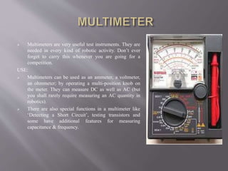
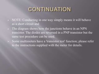
This document provides information on using voltmeters, ammeters, and multimeters. It discusses:
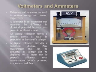
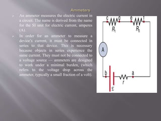
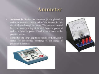
- How voltmeters measure voltage differences and ammeters measure electric current
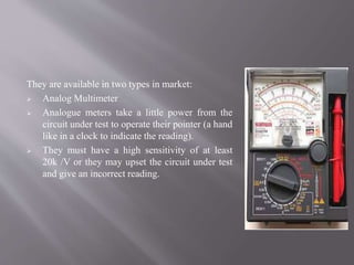
- That multimeters can measure voltage, current, and resistance by changing settings
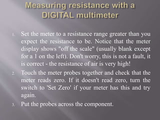
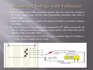
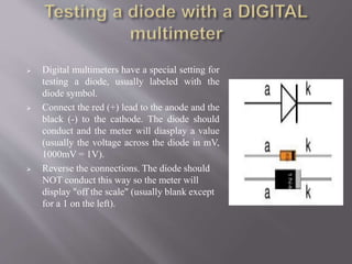
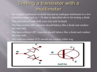
- Proper techniques for measuring voltage, current, resistance, and testing diodes and transistors using a multimeter