The document outlines a project report on designing a 'dark indicator' system aimed at improving energy efficiency for street lighting using an embedded system and light-dependent resistors (LDR). It highlights the project's purpose, methodology, and components involved, detailing the advantages of automated lighting control to reduce power wastage. The report includes acknowledgements, an abstract, circuit diagrams, and descriptions of components used in the project.


![14 | P a g e
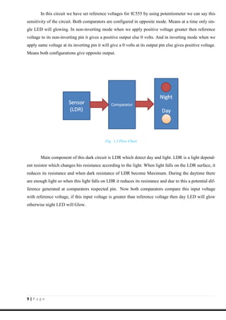
4.1 Battery
The nine-volt battery, or 9-volt battery, in its most common form was introduced for the ear-
ly transistor radios. It has a rectangular prism shape with rounded edges and a polarized snap connect-
or at the top. This type is commonly used in walkie talkies, clocks and smoke detectors. They are also
used as backup power to keep the time in certain electronic clocks. This format is commonly available
in primary carbon-zinc and alkaline chemistry, in primary lithium iron disulfide, and in rechargeable
form in nickel-cadmium, nickel-metal hydride and lithium-ion. Mercury oxide batteries in this form
have not been manufactured in many years due to their mercury content. This type is designat-
ed NEDA 1604 and IEC 6F22 (zinc-carbon) or MN1604 6LR61 (alkaline). The size, regardless of
technology, is commonly designated PP3 (originally a Zn-C type).
Most nine-volt alkaline batteries are constructed of six individual 1.5V LR61 cells enclosed in
a wrapper.[3]
These cells are slightly smaller than LR8D425 AAAA cells and can be used in their place
for some devices, even though they are 3.5 mm shorter. Carbon-zinc types are made with six flat cells
in a stack, enclosed in a moisture-resistant wrapper to prevent drying.
Fig. 4.1.1 Fig. 4.1.2](https://image.slidesharecdn.com/darkindicatorfinal2-190526183207/85/Dark-indicator-14-320.jpg)