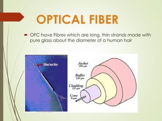
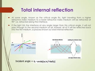
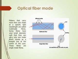
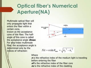
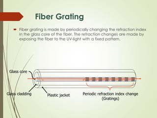
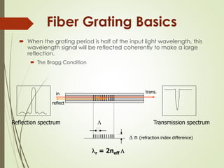
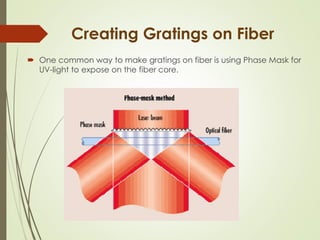
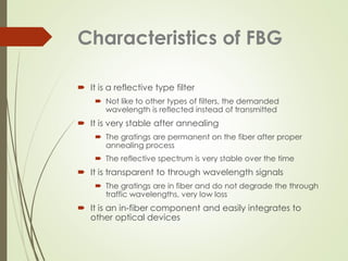
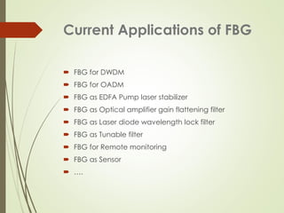
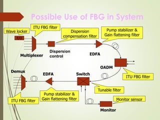
OPTICAL FIBER
SUB : PHYSICS.
SIGMA INSTITUTE OF TECHNOLOGY AND ENGINEERING
COMPUTER ENGG. (B.E)
Prepared by :
1. KAMALKANT MISTRY (150500107016)
2. JAIMIN PATEL (150500107026)
3. NISHIT SOLANKI (150500107039)
4. PRATIK NIMBALKAR (150500107033)
OPTICAL FIBER
 OFC have Fibres which are long, thin strands made with
pure glass about the diameter of a human hair
RAM NIWAS BAJIYA
Total internal reflection
 At some angle, known as the critical angle θc, light traveling from a higher
refractive index medium to a lower refractive index medium will be refracted at
90° i.e. refracted along the interface.
 If the light hits the interface at any angle larger than this critical angle, it will not
pass through to the second medium at all. Instead, all of it will be reflected back
into the first medium, a process known as total internal reflection
Incident angle =
Optical fiber mode
Fibbers that carry
more than one mode
at a specific light
wavelength are called
multimode fibres.
Some fibres have
very small diameter
core that they can
carry only one mode
which travels as a
straight line at the
centre of the core.
These fibres are
single mode fibres.
Optical fiber's Numerical
Aperture(NA)
Multimode optical fiber will
only propagate light that
enters the fiber within a
certain cone,
known as the acceptance
cone of the fiber. The half-
angle of this cone is called
the acceptance angle θmax.
For step-index multimode
fiber, the acceptance angle is
determined only by the
indices of refraction:
Where
n is the refractive index of the medium light is traveling
before entering the fiber
nf is the refractive index of the fiber core
nc is the refractive index of the cladding
Frequency Vs Attenuation In
Various Types of Cable
• More
information
carrying
capacity
fibbers can
handle
much
higher data
rates than
copper.
More
information
can be sent
in a second
Limitations of OFC
 Difficulty in jointing (splicing)
 Highly skilled staff would be required for maintenance
 Precision and costly instruments are required
 Tapping for emergency and gate communication is difficult.
 Costly if under- utilised
 Special interface equipment’s required for Block working
 Accept unipolar codes i.e. return to zero codes only.
Absorption & Attenuation
 Scattering of light due to molecular level irregularities in the glass
 Light absorption due to presence of residual materials, such as
metals or water ions, within the fiber core and inner cladding.
 These water ions that cause the “water peak” region on the
attenuation curve, typically around 1380 nm.
• Three peaks in attenuation
a). 1050 nm b). 1250 nm c). 1380 nm
• Three troughs in attenuation (Performance windows)
a.) 850 nm: 2 dB/km b). 1310 nm: 0.35 dB/km c). 1550 nm: 0.25 dB/km
Absorption loss & Scattering loss
Some of the advantages are:
 Compact in size
 High efficiency
 Good reliability
 Right wavelength range
 Small emissive area compatible with fibre core
dimensions
 Possibility of direct emulation at relatively high
frequencies
 high sensitivity
 fast response
 low noise
 low cost
 high reliability
Fiber Grating
 Fiber grating is made by periodically changing the refraction index
in the glass core of the fiber. The refraction changes are made by
exposing the fiber to the UV-light with a fixed pattern.
Glass core
Glass cladding Plastic jacket Periodic refraction index change
(Gratings)
Fiber Grating Basics
 When the grating period is half of the input light wavelength, this
wavelength signal will be reflected coherently to make a large
reflection.
 The Bragg Condition

r = 2neff 
in
Reflection spectrum
reflect
Transmission spectrum
trans.
 n (refraction index difference)
Creating Gratings on Fiber
 One common way to make gratings on fiber is using Phase Mask for
UV-light to expose on the fiber core.
Characteristics of FBG
 It is a reflective type filter
 Not like to other types of filters, the demanded
wavelength is reflected instead of transmitted
 It is very stable after annealing
 The gratings are permanent on the fiber after proper
annealing process
 The reflective spectrum is very stable over the time
 It is transparent to through wavelength signals
 The gratings are in fiber and do not degrade the through
traffic wavelengths, very low loss
 It is an in-fiber component and easily integrates to
other optical devices
Current Applications of FBG
 FBG for DWDM
 FBG for OADM
 FBG as EDFA Pump laser stabilizer
 FBG as Optical amplifier gain flattening filter
 FBG as Laser diode wavelength lock filter
 FBG as Tunable filter
 FBG for Remote monitoring
 FBG as Sensor
 ….
Possible Use of FBG in System
Multiplexer
Dispersion
control
EDFA
OADM
SwitchEDFA
Demux
ITU FBG filter
Dispersion
compensation filter
Pump stabilizer &
Gain flattening filter
ITU FBG filter
Tunable filter
ITU FBG filter
Pump stabilizer &
Gain flattening filter
E/O
Wave locker
Monitor
Monitor sensor
HeM’s Editor

Optical Fiber

  • 1.
    OPTICAL FIBER SUB :PHYSICS. SIGMA INSTITUTE OF TECHNOLOGY AND ENGINEERING COMPUTER ENGG. (B.E) Prepared by : 1. KAMALKANT MISTRY (150500107016) 2. JAIMIN PATEL (150500107026) 3. NISHIT SOLANKI (150500107039) 4. PRATIK NIMBALKAR (150500107033)
  • 2.
    OPTICAL FIBER  OFChave Fibres which are long, thin strands made with pure glass about the diameter of a human hair RAM NIWAS BAJIYA
  • 3.
    Total internal reflection At some angle, known as the critical angle θc, light traveling from a higher refractive index medium to a lower refractive index medium will be refracted at 90° i.e. refracted along the interface.  If the light hits the interface at any angle larger than this critical angle, it will not pass through to the second medium at all. Instead, all of it will be reflected back into the first medium, a process known as total internal reflection Incident angle =
  • 4.
    Optical fiber mode Fibbersthat carry more than one mode at a specific light wavelength are called multimode fibres. Some fibres have very small diameter core that they can carry only one mode which travels as a straight line at the centre of the core. These fibres are single mode fibres.
  • 5.
    Optical fiber's Numerical Aperture(NA) Multimodeoptical fiber will only propagate light that enters the fiber within a certain cone, known as the acceptance cone of the fiber. The half- angle of this cone is called the acceptance angle θmax. For step-index multimode fiber, the acceptance angle is determined only by the indices of refraction: Where n is the refractive index of the medium light is traveling before entering the fiber nf is the refractive index of the fiber core nc is the refractive index of the cladding
  • 6.
    Frequency Vs AttenuationIn Various Types of Cable • More information carrying capacity fibbers can handle much higher data rates than copper. More information can be sent in a second
  • 7.
    Limitations of OFC Difficulty in jointing (splicing)  Highly skilled staff would be required for maintenance  Precision and costly instruments are required  Tapping for emergency and gate communication is difficult.  Costly if under- utilised  Special interface equipment’s required for Block working  Accept unipolar codes i.e. return to zero codes only.
  • 8.
    Absorption & Attenuation Scattering of light due to molecular level irregularities in the glass  Light absorption due to presence of residual materials, such as metals or water ions, within the fiber core and inner cladding.  These water ions that cause the “water peak” region on the attenuation curve, typically around 1380 nm.
  • 9.
    • Three peaksin attenuation a). 1050 nm b). 1250 nm c). 1380 nm • Three troughs in attenuation (Performance windows) a.) 850 nm: 2 dB/km b). 1310 nm: 0.35 dB/km c). 1550 nm: 0.25 dB/km Absorption loss & Scattering loss
  • 10.
    Some of theadvantages are:  Compact in size  High efficiency  Good reliability  Right wavelength range  Small emissive area compatible with fibre core dimensions  Possibility of direct emulation at relatively high frequencies  high sensitivity  fast response  low noise  low cost  high reliability
  • 11.
    Fiber Grating  Fibergrating is made by periodically changing the refraction index in the glass core of the fiber. The refraction changes are made by exposing the fiber to the UV-light with a fixed pattern. Glass core Glass cladding Plastic jacket Periodic refraction index change (Gratings)
  • 12.
    Fiber Grating Basics When the grating period is half of the input light wavelength, this wavelength signal will be reflected coherently to make a large reflection.  The Bragg Condition  r = 2neff  in Reflection spectrum reflect Transmission spectrum trans.  n (refraction index difference)
  • 13.
    Creating Gratings onFiber  One common way to make gratings on fiber is using Phase Mask for UV-light to expose on the fiber core.
  • 14.
    Characteristics of FBG It is a reflective type filter  Not like to other types of filters, the demanded wavelength is reflected instead of transmitted  It is very stable after annealing  The gratings are permanent on the fiber after proper annealing process  The reflective spectrum is very stable over the time  It is transparent to through wavelength signals  The gratings are in fiber and do not degrade the through traffic wavelengths, very low loss  It is an in-fiber component and easily integrates to other optical devices
  • 15.
    Current Applications ofFBG  FBG for DWDM  FBG for OADM  FBG as EDFA Pump laser stabilizer  FBG as Optical amplifier gain flattening filter  FBG as Laser diode wavelength lock filter  FBG as Tunable filter  FBG for Remote monitoring  FBG as Sensor  ….
  • 16.
    Possible Use ofFBG in System Multiplexer Dispersion control EDFA OADM SwitchEDFA Demux ITU FBG filter Dispersion compensation filter Pump stabilizer & Gain flattening filter ITU FBG filter Tunable filter ITU FBG filter Pump stabilizer & Gain flattening filter E/O Wave locker Monitor Monitor sensor
  • 17.