Download to read offline


![Third Year Engineering Programming Laboratory - III
2 | Pune Vidyarthi Griha’s COLLEGE OF ENGINEERING, NASIK
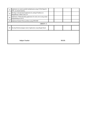
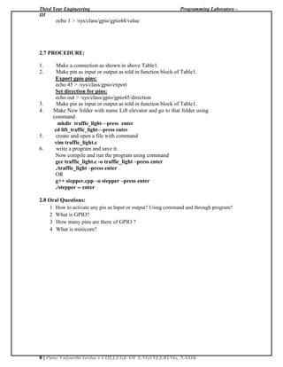
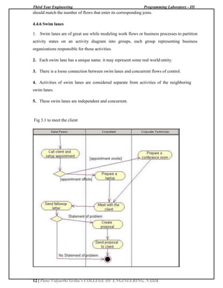
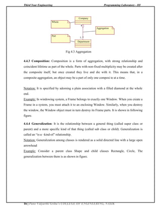
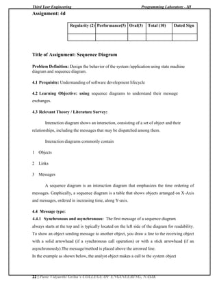
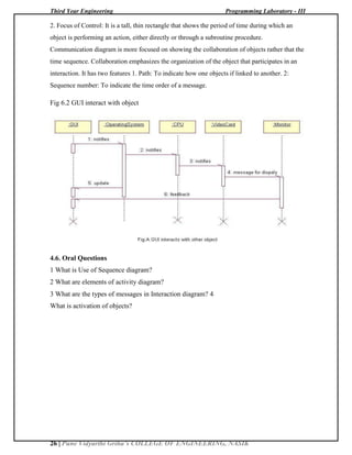
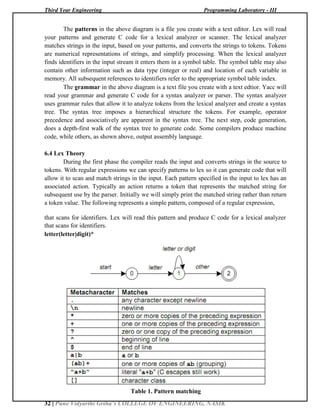
1.5 CONNECTOR DETAILS:
Connector PIN PIN Description PIN connects to board Function
Number
Number
P9 1,2 GND GND(25pin) GND
P9 3,4 VCC(3.6V) VCC(26pin) VCC
P8 7 GPIO2[2] FRC-6pin In
P8 8 GPIO2[3] FRC-5pin In
P8 9 GPIO2[5] FRC-4pin In
P8 10 GPIO2[4] FRC-3pin In
P8 11 GPIO1[13] FRC-13pin Out
P8 12 GPIO1[12] FRC-14pin Out
P8 13 GPIO0[23] FRC-11pin Out
P8 14 GPIO0[26] FRC-12pin Out
P8 15 GPIO1[15] FRC-9pin Out
P8 16 GPIO1[14] FRC-10pin Out
P8 17 GPIO0[27] FRC-7pin Out
P8 18 GPIO2[1] FRC-8pin Out
P8 19 GPIO0[22] FRC-23pin Out
P8 21 GPIO1[30] FRC-24pin Out
P9 11 GPIO0[30] FRC-21pin Out
P9 12 GPIO1[28] FRC-22pin Out
P9 13 GPIO0[31] FRC-19pin Out
P9 14 GPIO1[18] FRC-20pin Out
P9 15 GPIO1[16] FRC-17pin Out
P9 16 GPIO1[19] FRC-18pin Out](https://image.slidesharecdn.com/newpl-3manual2017-180104184140/85/PL-3-LAB-MANUAL-6-320.jpg)
![Third Year Engineering Programming Laboratory - III
3 | Pune Vidyarthi Griha’s COLLEGE OF ENGINEERING, NASIK
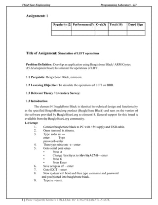
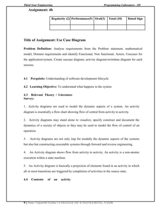
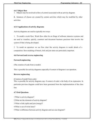
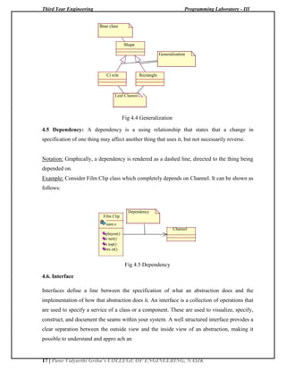
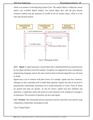
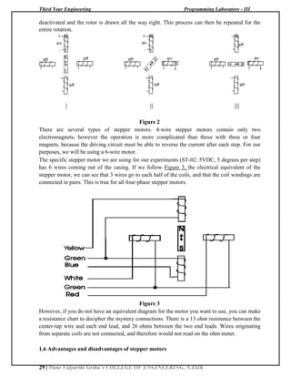
TABLE 1
1.6 How to get GPIO pin number:
•Once you have decided the pin number which you would like to use as a GPIO, you need to
find out its corresponding reference number.
•For example, if you would like to use pin 12 on P8 expansion header, Then find out its default
function. Note down the entire signal name. In this case, pin 12 is GPIO1_12.So any GPIO
you come across would be referenced as GPIOX_Y. Identify X,Y.
• Use the formula below to find the corresponding reference number:
Reference number =( (X*32 )+ Y )
Hence, pin 12 would be referenced as gpio 44 in the kernel.
1.7 To use GPIO pin as GPIO in programs follow the steps :
• To make GPIO pin xx as output type command in terminal(xx—pin
number)
echo xx > /sys/class/gpio/export -- press enter
echo out > /sys/class/gpio/gpioxx/direction --press enter
for example:
echo 44 > /sys/class/gpio/export
echo out > /sys/class/gpio/gpio44/direction
• To make GPIO pin xx as input type command in terminal(xx—pin
number)
echo xx > /sys/class/gpio/export -- press enter
echo in > /sys/class/gpio/gpioxx/direction --press enter
for example:
echo 44 > /sys/class/gpio/export
echo in > /sys/class/gpio/gpio44/direction
• After making GIPO pin as output, To change the initial value of
output pin type command in
terminal(x—1/0,xx—pin number)
echo x > /sys/class/gpio/gpioxx/value –press enter
for example:
echo 0 > /sys/class/gpio/gpio44/value
OR
echo 1 > /sys/class/gpio/gpio44/value
1.8 PROCEDURE:
1. Make a connection as shown in above Table1.
2. Make pin as input or output as told in function block of Table1.
Export pins :
echo 45 > /sys/class/gpio/export
P9 23 GPIO1[17] FRC-16pin Out
P9 24 GPIO0[15] FRC-15pin Out](https://image.slidesharecdn.com/newpl-3manual2017-180104184140/85/PL-3-LAB-MANUAL-7-320.jpg)

![Third Year Engineering Programming Laboratory - III
6 | Pune Vidyarthi Griha’s COLLEGE OF ENGINEERING, NASIK
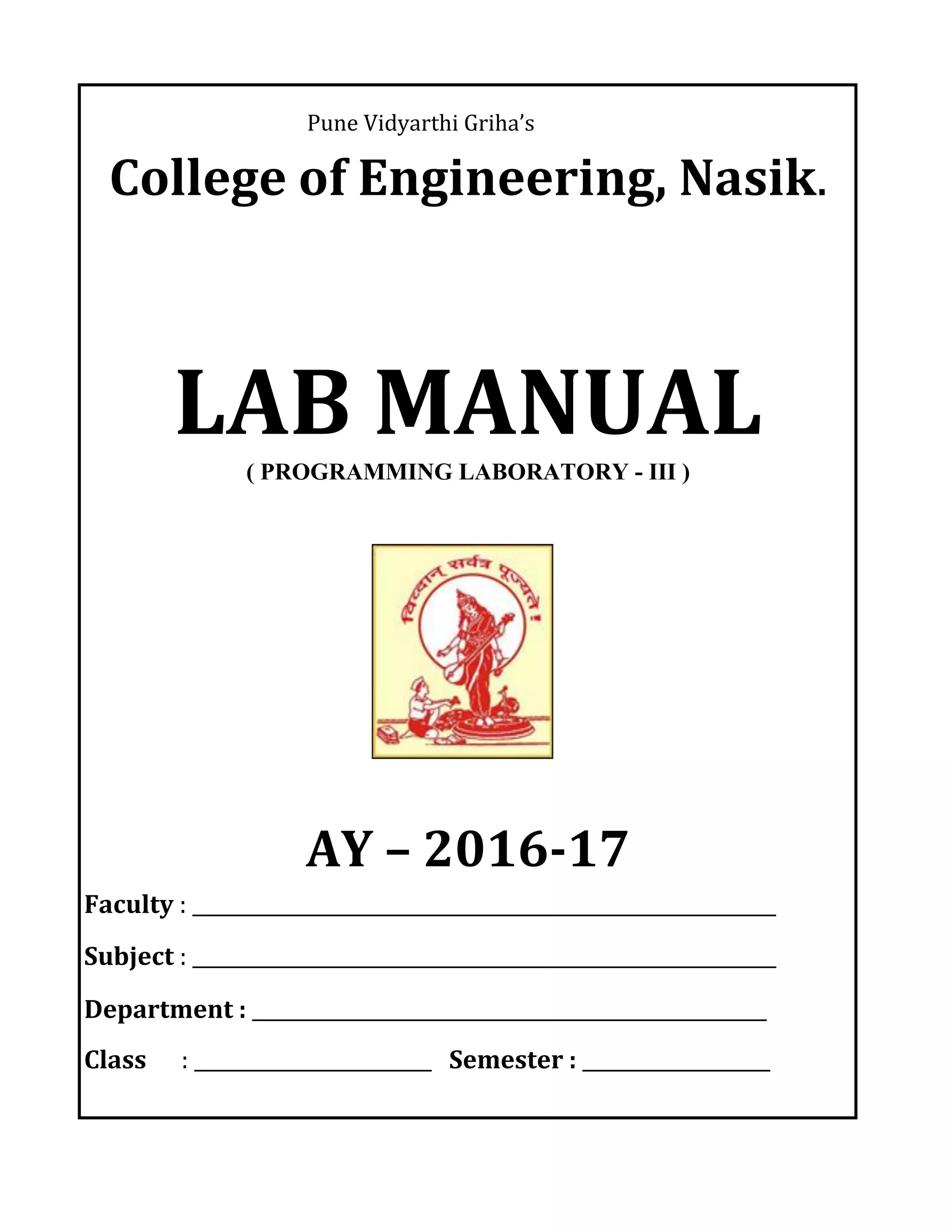
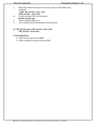
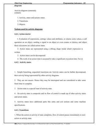
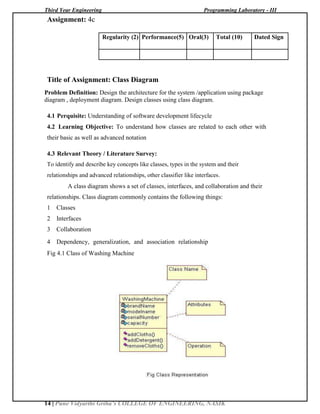
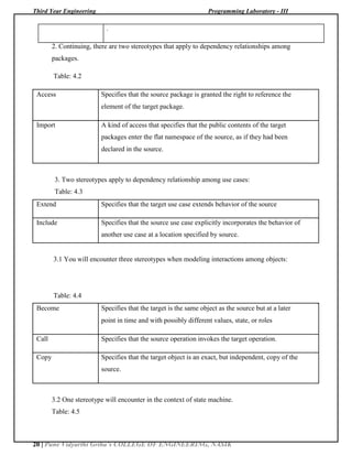
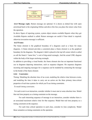
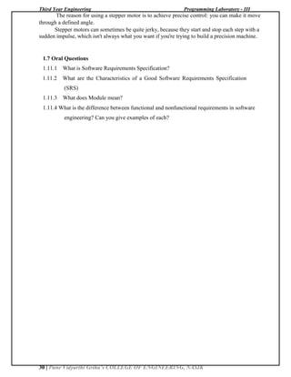
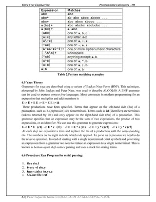
2.4 CONNECTOR DETAILS:
TABLE 1
Connector PIN PIN Description PIN connects to accessory Function
Number
Number
board
P9 1,2 GND GND(25pin) GND
P9 5 VCC(5V) VCC(26pin) VCC
P9 11 GPIO0[30] FRC21pin Out
P9 12 GPIO1[28] FRC-22pin Out
P9 13 GPIO0[31] FRC-19pin Out
P9 14 GPIO1[18] FRC-20pin Out
P9 15 GPIO1[16] FRC-17pin Out
P9 16 GPIO1[19] FRC-18pin Out
P9 24 GPIO0[15] FRC-15pin Out
P9 23 GPIO1[17] FRC-16pin Out
P8 11 GPIO1[13] FRC-13pin Out
P8 12 GPIO1[12] FRC-14pin Out
P8 13 GPIO0[23] FRC-11pin Out
P8 14 GPIO0[26] FRC-12pin Out
P8 15 GPIO1[15] FRC-9pin Out
P8 16 GPIO1[14] FRC-10pin Out
P8 17 GPIO0[27] FRC-7pin Out
P8 18 GPIO2[1] FRC-8pin Out](https://image.slidesharecdn.com/newpl-3manual2017-180104184140/85/PL-3-LAB-MANUAL-10-320.jpg)
![Third Year Engineering Programming Laboratory - III
18 | Pune Vidyarthi Griha’s COLLEGE OF ENGINEERING, NASIK
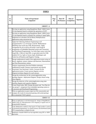
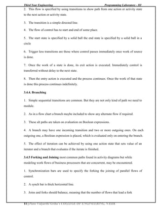
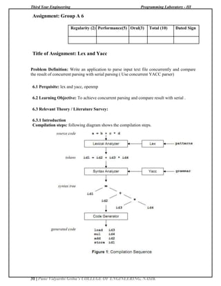
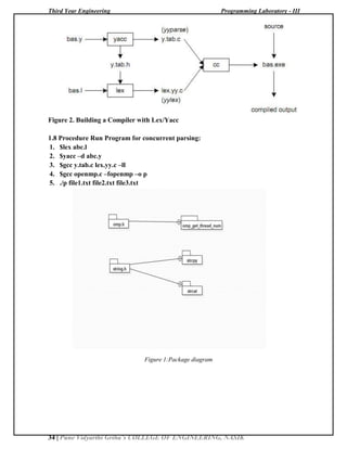
abstraction without having to dive into the details of its implementation.
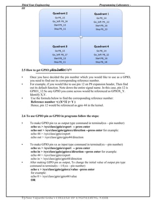
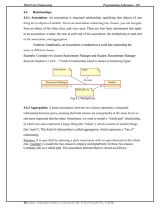
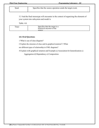
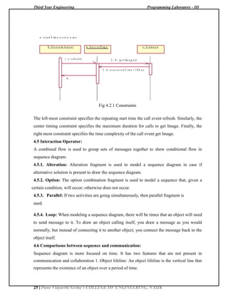
Every interface must have a name that distinguishes it from other interface. An interface is
drawn showing only its name, as in figure.
An interface is a named collection of operations used to specify a service of a class or of a
component. Like a class, an interface may have any number of operations. These operations
may be adorned with visibility properties, concurrency properties, stereotypes, tagged values,
and constraints.
Stereotype
<<Interfac e>> URL
StreamHandler
OpenConnect ion() Operat ions
ParseURL()
Set URL()
ToExternal Form ()
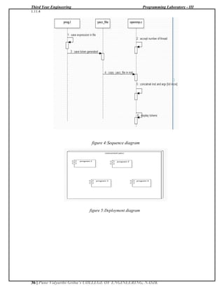
Fig 4.6 Interface
4.7. Operation Constraint: The name of the operation plus its parameters (including
return type, if any) is called the operation’s signature.
In its full form, the syntax of an operation in the UML is
[visibility] name [(parameter-list)]
[: return-type] [{property-string}]
For example, the following are all legal operation declaration:
1 Display Name only
2 +Display Visibility and name
3 Set (n: Name, s: String) Name and parameters
4 getId() : Integer Name and return type
5 restart() {guarded} Name and property](https://image.slidesharecdn.com/newpl-3manual2017-180104184140/85/PL-3-LAB-MANUAL-22-320.jpg)
![Third Year Engineering Programming Laboratory - III
19 | Pune Vidyarthi Griha’s COLLEGE OF ENGINEERING, NASIK
In an operation signature, you may provide zero or more parameters, each of which
follows the syntax
[Direction] name: type [= default-value]
Direction may be of the following values:
In an input parameter; may not be modified
Out an output parameter; may be modified to communicate information to the caller In
out an input parameter; may be modified.
4.8 Different Stereotypes:
A plain, unadorned dependency relationship is sufficient for most of the using
relationships. However, if you want to specify a shade of meaning, the UML defines a
number of stereotypes that may be applied to dependency relationships. There are 17 such
stereotypes, all of which can be organized in 6 groups.
1. First, there are eight stereotypes that apply to dependency relationships among classes
and object in class diagrams.
Table: 4.1
Bind Specifies that the source instantiates the target template using the given
actual parameters.
Derive Specifies that the source may be computed from the target
Friend Specifies that source is given special visibility into the target
Instance Of Specifies that the source object is an instance of the target classifier
Instantiate Specifies that source creates instances of the target
Power type Specifies that the target is a power type of the source; a power type is a
classifier whose objects are all the children of given parent.
Refine Specifies that the source is at a finer degree of abstraction that the target
Use
Specifies that the semantics of the source element depends on the semantics of
the public part of the target](https://image.slidesharecdn.com/newpl-3manual2017-180104184140/85/PL-3-LAB-MANUAL-23-320.jpg)
![Third Year Engineering Programming Laboratory - III
27 | Pune Vidyarthi Griha’s COLLEGE OF ENGINEERING, NASIK
Assignment: A5
Regularity (2) Performance(5) Oral(3) Total (10) Dated Sign
Title of Assignment: Software Requirement Specification (SRS)
Problem Definition: Create Project plan, SRS, Design document and Test Plan for one
group-C assignment from embedded operating system or Concurrent and Distributed
Programming
Problem Definition: Develop Robotics(stepper motor) Application using Beagle Board.
1.1 Perquisite: Beaglebone Black, minicom
1.2 Learning Objective: To simulate the operations of LIFT on BBB.
1.3 Relevant Theory / Literature Survey:
1.3 Introduction
The element14 BeagleBone Black is identical in technical design and functionality as the
specified BeagleBoard.org product (BeagleBone Black) and runs on the version of the software
provided by BeagleBoard.org to element14. General support for this board is available from the
BeagleBoard.org community.
1.4 CONNECTOR DETAILS:
Connector PIN PIN Description PIN connects to board Function
Number
Number
P9 1,2 GND GND(25pin) GND
P9 5 VCC(5V) VCC(26pin) VCC
P9 11 GPIO0[30] FRC-21pin Out
P9 12 GPIO1[28] FRC-22pin Out
P9 13 GPIO0[31] FRC-19pin Out](https://image.slidesharecdn.com/newpl-3manual2017-180104184140/85/PL-3-LAB-MANUAL-31-320.jpg)
![Third Year Engineering Programming Laboratory - III
28 | Pune Vidyarthi Griha’s COLLEGE OF ENGINEERING, NASIK
P9 14 GPIO1[18] FRC-20pin Out
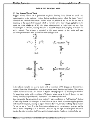
Table 1: Pins for stepper motor
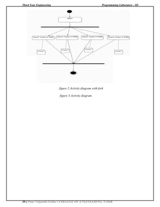
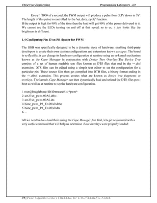
1.5 How Stepper Motors Work
Stepper motors consist of a permanent magnetic rotating shaft, called the rotor, and
electromagnets on the stationary portion that surrounds the motor, called the stator. Figure 1
illustrates one complete rotation of a stepper motor. At position 1, we can see that the rotor is
beginning at the upper electromagnet, which is currently active (has voltage applied to it). To
move the rotor clockwise (CW), the upper electromagnet is deactivated and the right
electromagnet is activated, causing the rotor to move 90 degrees CW, aligning itself with the
active magnet. This process is repeated in the same manner at the south and west electromagnets
until we once again reach the starting position.
Figure 1
In the above example, we used a motor with a resolution of 90 degrees or demonstration
purposes. In reality, this would not be a very practical motor for most applications. The average
stepper motor's resolution -- the amount of degrees rotated per pulse -- is much higher than this.
For example, a motor with a resolution of 5 degrees would move its rotor 5 degrees per step,
thereby requiring 72 pulses (steps) to complete a full 360 degree rotation.
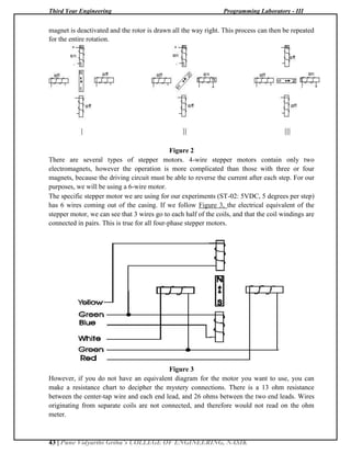
You may double the resolution of some motors by a process known as "half-stepping". Instead
of switching the next electromagnet in the rotation on one at a time, with half stepping you turn
on both electromagnets, causing an equal attraction between, thereby doubling the resolution. As
you can see in Figure 2, in the first position only the upper electromagnet is active, and the rotor
is drawn completely to it. In position 2, both the top and right electromagnets are active, causing
the rotor to position itself between the two active poles. Finally, in position 3, the top magnet is](https://image.slidesharecdn.com/newpl-3manual2017-180104184140/85/PL-3-LAB-MANUAL-32-320.jpg)

![Third Year Engineering Programming Laboratory - III
41 | Pune Vidyarthi Griha’s COLLEGE OF ENGINEERING, NASIK
Assignment: Group C1
Regularity (2) Performance(5) Oral(3) Total (10) Dated Sign
Title of Assignment: Stepper Motor
Problem Definition: Develop Robotics(stepper motor) Application using Beagle Board.
1.1 Perquisite: Beaglebone Black, minicom
1.2 Learning Objective: To simulate the operations of LIFT on BBB.
1.3 Relevant Theory / Literature Survey:
1.3 Introduction
The element14 BeagleBone Black is identical in technical design and functionality as
the specified BeagleBoard.org product (BeagleBone Black) and runs on the version of the
software provided by BeagleBoard.org to element14. General support for this board is available
from the BeagleBoard.org community.
1.4 CONNECTOR DETAILS:
Connector PIN PIN Description PIN connects to board Function
Number
Number
P9 1,2 GND GND(25pin) GND
P9 5 VCC(5V) VCC(26pin) VCC
P9 11 GPIO0[30] FRC-21pin Out
P9 12 GPIO1[28] FRC-22pin Out
P9 13 GPIO0[31] FRC-19pin Out
P9 14 GPIO1[18] FRC-20pin Out](https://image.slidesharecdn.com/newpl-3manual2017-180104184140/85/PL-3-LAB-MANUAL-45-320.jpg)
The document describes a laboratory manual for Programming Laboratory - III. It contains 18 assignments divided into three groups - A, B, and C. The assignments include developing applications using a BeagleBone Black board to simulate operations like a lift and traffic lights, implementing a calculator using concurrent Lisp, applying software engineering methodologies to assignments, designing mathematical models, analyzing requirements and creating UML diagrams. It provides the setup instructions, relevant theory, and procedures to complete the assignments.