ASM Concept &Problem-Solving
Questions
20 Concept Questions and 10
Problem Solving Questions with
Solutions
2.
Concept Questions
• 1.What does ASM stand for?
Answer: Algorithmic State Machine
• 2. What type of circuit is ASM used to design?
Answer: Synchronous sequential circuits
• 3. What are the three main components of an
ASM chart?
Answer: State box, Decision box, Conditional
output box
3.
Concept Questions
• 6.What distinguishes ASM from a regular
state diagram?
Answer: ASM includes operations and
decisions in each state
• 7. What hardware elements typically
implement ASM logic?
Answer: Flip-flops, multiplexers, and logic
gates
• 8. In ASM, where are output actions defined?
4.
Concept Questions
• 11.What condition is associated with a
decision box?
Answer: Boolean input conditions
• 12. Is ASM suitable for asynchronous systems?
Answer: No
• 13. Which part of ASM handles conditional
output actions?
Answer: Conditional output box
5.
Concept Questions
• 16.ASM can be considered as an enhanced
version of what?
Answer: State diagram
• 17. What does ASM help visualize clearly?
Answer: Control and data flow
• 18. Can multiple outputs be defined in one
state box?
Answer: Yes
6.
Problem Solving Questions
•1. Design an ASM chart for a 2-state toggle
switch (On/Off).
Solution: States: S0 (Off), S1 (On)
Input: Toggle
Transitions: S0 -> Toggle=1 -> S1, S1 ->
Toggle=1 -> S0
• 2. Given an ASM with states A, B, C and input
X, define next state transitions.
Solution: A -> X=1 -> B, B -> X=0 -> C, C ->
7.
Problem Solving Questions
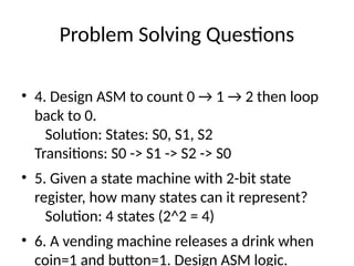
•4. Design ASM to count 0 → 1 → 2 then loop
back to 0.
Solution: States: S0, S1, S2
Transitions: S0 -> S1 -> S2 -> S0
• 5. Given a state machine with 2-bit state
register, how many states can it represent?
Solution: 4 states (2^2 = 4)
• 6. A vending machine releases a drink when
coin=1 and button=1. Design ASM logic.
8.
Problem Solving Questions
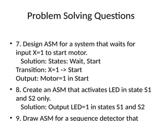
•7. Design ASM for a system that waits for
input X=1 to start motor.
Solution: States: Wait, Start
Transition: X=1 -> Start
Output: Motor=1 in Start
• 8. Create an ASM that activates LED in state S1
and S2 only.
Solution: Output LED=1 in states S1 and S2
• 9. Draw ASM for a sequence detector that
9.
Problem Solving Questions
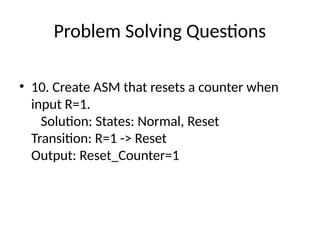
•10. Create ASM that resets a counter when
input R=1.
Solution: States: Normal, Reset
Transition: R=1 -> Reset
Output: Reset_Counter=1