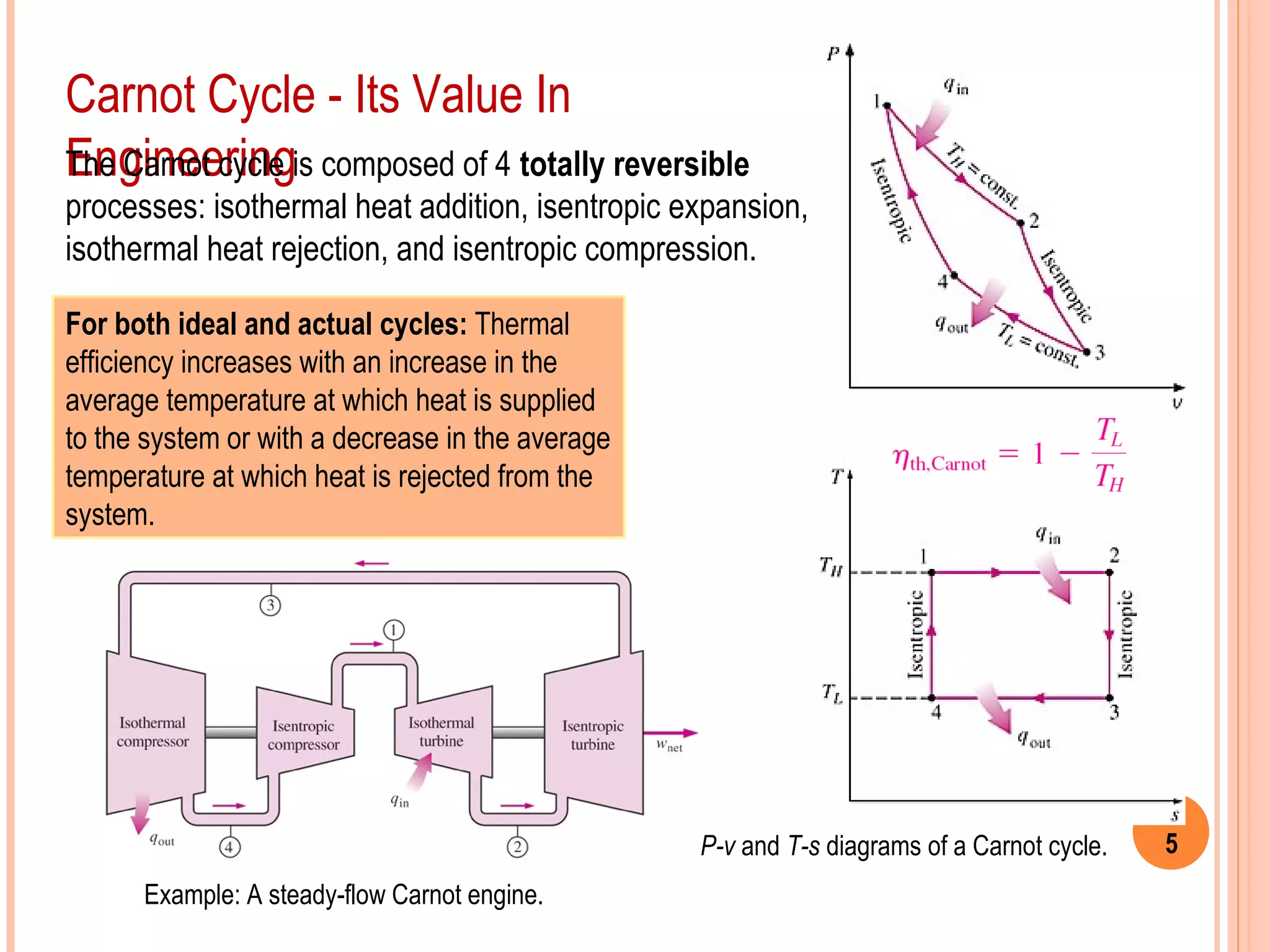
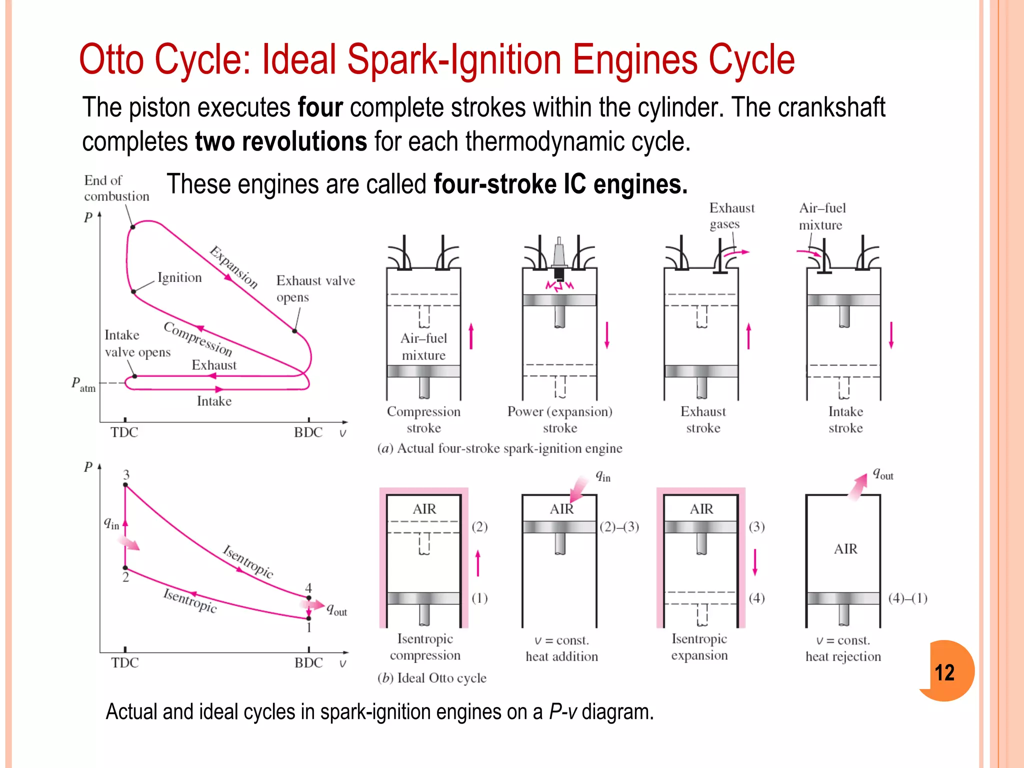
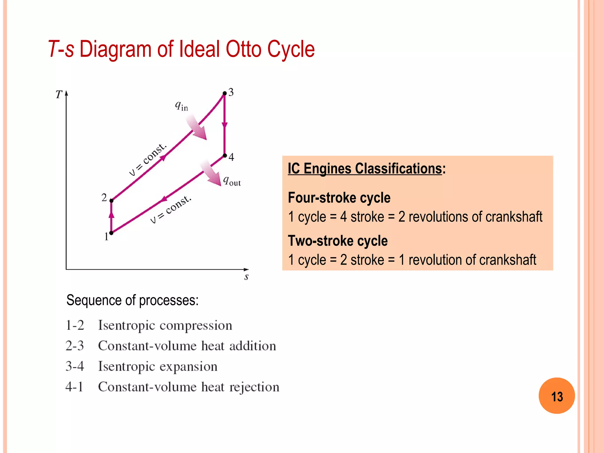
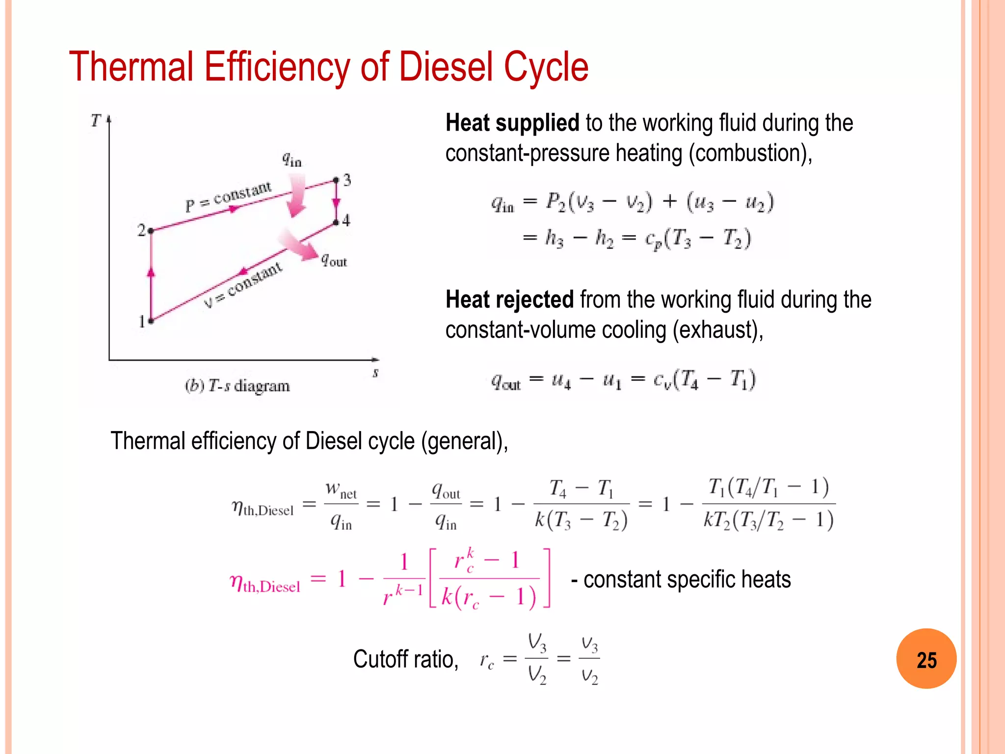
SlideShare a Scribd company logo
Chapter 9
GAS POWER CYCLES
(Part 1a)
Copyright © The McGraw-Hill Companies, Inc. Permission required for reproduction or display.
Thermodynamics: An Engineering Approach, 6th
Edition
Yunus A. Cengel, Michael A. Boles
McGraw-Hill, 2008
2
Objectives
1. Evaluate the performance of gas power cycles.
2. Develop simplifying assumptions applicable to gas power cycles.
3. Review the operation of reciprocating engines.
4. Analyze both closed and open gas power cycles.
5. Solve problems based on the Otto and Diesel cycles.
6. Solve problems based on the Brayton cycle; Brayton cycle with regeneration;
and Brayton cycle with intercooling, reheating, and regeneration.
7. Identify simplifying assumptions and perform second-law analysis on gas
power cycles.
3
Basic Considerations In Power Cycles Analysis
The analysis of many complex
processes can be reduced to a
manageable level by utilizing
some idealizations.
Most power-producing devices operate on cycles.
Ideal cycle: A cycle that resembles the actual cycle
closely but is made up totally of internally reversible
processes is called an ideal cycle.
Recall: Thermal efficiency of heat engines
Reversible cycles such as Carnot cycle have the
highest thermal efficiency of all heat engines operating
between the same temperature levels.
Unlike ideal cycles, they are totally reversible, and
unsuitable as a realistic model.
4
1. The cycle does not involve any friction. Therefore,
the working fluid does not experience any pressure
drop as it flows in pipes or heat exchangers.
2. All expansion and compression processes take
place in a quasi-equilibrium manner.
3. The pipes connecting the various components of a
system are well insulated, so heat transfer
through them is negligible.
Care should be exercised in the
interpretation of the results from
ideal cycles.
On both P-v and T-s diagrams, the area enclosed by the
process curve represents the net work of the cycle.
On a T-s diagram, the ratio of the area
enclosed by the cyclic curve to the area
under the heat-addition process curve
represents the thermal efficiency of the
cycle.
Idealizations (simplifications) in the analysis of power cycles
5
Carnot Cycle - Its Value In
Engineering
P-v and T-s diagrams of a Carnot cycle.
Example: A steady-flow Carnot engine.
The Carnot cycle is composed of 4 totally reversible
processes: isothermal heat addition, isentropic expansion,
isothermal heat rejection, and isentropic compression.
For both ideal and actual cycles: Thermal
efficiency increases with an increase in the
average temperature at which heat is supplied
to the system or with a decrease in the average
temperature at which heat is rejected from the
system.
6
Air-standard Assumptions
The combustion process is replaced by a
heat-addition process in ideal cycles.
1. The working fluid is air, which continuously
circulates in a closed loop and always
behaves as an ideal gas.
2. All the processes that make up the cycle
are internally reversible.
3. The combustion process is replaced by a
heat-addition process from an external
source.
4. The exhaust process is replaced by a
heat-rejection process that restores the
working fluid to its initial state.
Cold-air-standard assumptions: When the working fluid is considered to be air
with constant specific heats at room temperature (25°C).
Air-standard cycle: A cycle for which the air-standard assumptions are
applicable.
Chapter 9
GAS POWER CYCLES
(Part 1b)
Copyright © The McGraw-Hill Companies, Inc. Permission required for reproduction or display.
Thermodynamics: An Engineering Approach, 6th
Edition
Yunus A. Cengel, Michael A. Boles
McGraw-Hill, 2008
8
Problem
Otto Cycle
9–34
An ideal Otto cycle has a compression ratio of 8. At the beginning of the
compression process, air is at 95 kPa and 27°C, and 750 kJ/kg of heat is
transferred to air during the constant-volume heat-addition process. Assuming
that the specific heats are constant with temperature, determine:
• the pressure & temperature at the end of heat addition process,
• the net work output,
• the thermal efficiency, and
• the mean effective pressure for the cycle.
Answers: (a) 3898 kPa, 1539 K, (b) 392.4 kJ/kg, (c) 52.3 percent, (d ) 495 kPa
9
Overview of Reciprocating Engines
The reciprocating engine (basically a piston–cylinder device) is an invention that
has proved to be very versatile and has a wide range of applications.
Reciprocating engine is the
powerhouse of the vast majority
of automobiles, trucks, light
aircraft, ships, electric power
generators, and many other
devices.
10
Basic Components
Compression ratio:
The piston reciprocates in the cylinder between two fixed positions called the top dead
centre (TDC) - the position that forms the smallest volume in the cylinder - and the bottom
dead centre (BDC) - position that forms the largest volume in the cylinder.
The distance between TDC and BDC is called the stroke of
the engine. The diameter of the piston is called the bore.
11
Performance Characteristics
Classifications of IC Engines:
1. Spark-ignition (SI) or Petrol engines
2. Compression-ignition (CI) or Diesel
engines
Mean effective pressure (MEP):
A fictitious pressure that, if it is acted on the piston
during the entire power stroke, would produce the
same amount of net work as that produced during the
actual cycle.
Net work output per cycle:
12
Otto Cycle: Ideal Spark-Ignition Engines Cycle
Actual and ideal cycles in spark-ignition engines on a P-v diagram.
The piston executes four complete strokes within the cylinder. The crankshaft
completes two revolutions for each thermodynamic cycle.
These engines are called four-stroke IC engines.
13
T-s Diagram of Ideal Otto Cycle
IC Engines Classifications:
Four-stroke cycle
1 cycle = 4 stroke = 2 revolutions of crankshaft
Two-stroke cycle
1 cycle = 2 stroke = 1 revolution of crankshaft
Sequence of processes:
14
In two-stroke engines, all four functions described earlier are executed in two
strokes: the power and compression stroke.
Generally less efficient, but are relatively simple and inexpensive. They have high
power-to-weight and power-to-volume ratios.
Two-Stroke IC Engines
15
Thermal Efficiency of Otto Cycle
The heat supplied to the working fluid during
constant-volume heating (combustion),
The heat rejected from the working fluid during
constant-volume cooling (exhaust),
Thermal efficiency,
Temperature-volume relation,
Compression ratio,
Cold-air standard assumption.
16
Problem
Otto Cycle
9–34B
Reconsider the ideal Otto cycle in Problem 9-34. Assuming that the specific
heats vary with temperature, determine:
• the pressure & temperature at the end of heat addition process,
• the net work output,
• the thermal efficiency, and
• the mean effective pressure for the cycle.
Answers: (a) 3898 kPa, 1539 K, (b) 392.4 kJ/kg, (c) 52.3 percent, (d ) 495 kPa
17
Problem
Otto Cycle
9–37
The compression ratio of an air-standard Otto cycle is 9.5. Prior to the isentropic
compression process, the air is at 100 kPa, 35°C, and 600 cm3
. The temperature
at the end of the isentropic expansion process is 800 K. Using specific heat
values at room temperature, determine:
• the highest temperature and pressure in the cycle;
• the amount of heat transferred in, in kJ;
• the thermal efficiency; and
• the mean effective pressure.
Answers: (a) 1969 K, 6072 kPa, (b) 0.59 kJ, (c) 59.4 percent, (d) 652 kPa
18
Problem
9–39E
An ideal Otto cycle with air as the working fluid has a compression ratio of 8.
The minimum and maximum temperatures in the cycle are 300 K and 1340 K.
Accounting for the variation of specific heats with temperature, determine:
• the amount of heat transferred to the air during heat-addition process,
• the thermal efficiency, and
• the thermal efficiency of a Carnot cycle operating between the same
temperature limits.
Otto Cycle
Class Exercise
19
Premature ignition of the fuel produces audible noise called engine knock. It hurts
performance and causes engine damage.
Autoignition places upper limit on compression ratios that can be used in SI engines.
Specific heat ratio, k affects the thermal efficiency of the Otto cycle.
Engine Knock (Autoignition)
20
Problem
Otto Cycle
9–41
A four-cylinder, four-stroke, 2.2-L gasoline engine operates on the Otto cycle with
a compression ratio of 10. The air is at 100 kPa and 60°C at the beginning of the
compression process, and the maximum pressure in the cycle is 8 MPa. The
compression and expansion processes may be modeled as polytropic with an
index of 1.3. Using constant specific heats at 850 K, determine:
• the temperature at the end of the expansion process,
• the net work output and the thermal efficiency,
• the mean effective pressure,
• the engine speed for a net power output of 70 kW, and
• the specific fuel consumption, in g/kWh, defined as the ratio of the mass
of the fuel consumed to the net work produced.
Note: The air–fuel ratio, defined as the amount of air divided by the amount of
fuel intake, is 16.
Chapter 9
GAS POWER CYCLES
(Part 1c)
Copyright © The McGraw-Hill Companies, Inc. Permission required for reproduction or display.
Thermodynamics: An Engineering Approach, 6th
Edition
Yunus A. Cengel, Michael A. Boles
McGraw-Hill, 2008
22
Problem
Diesel Cycle
9–47
An air-standard Diesel cycle has a compression ratio of 16 and a cutoff ratio of
2. At the beginning of the compression process, air is at 95 kPa and 27°C.
Accounting for the variation of specific heats with temperature, determine:
• the temperature after the heat-addition process,
• the thermal efficiency, and
• the mean effective pressure.
Answers: (a) 1724.8 K, (b) 56.3 percent, (c) 675.9 kPa
23
Diesel Cycle: Ideal Cycle for CI Engines
The combustion process takes place over a
longer interval - fuel injection starts when
the piston approaches TDC and continues
during the first part of power stroke.
Hence, combustion process in the ideal
Diesel cycle is approximated as a constant-
pressure heat-addition process.
In diesel engines, only air is compressed during the compression stroke, eliminating
the possibility of autoignition. These engines can be designed to operate at higher
compression ratios, typically between 12 and 24.
Fuels that are less refined (thus less expensive) can be used in diesel engines.
24
1-2 Isentropic compression
2-3 Constant-pressure heat addition
3-4 Isentropic expansion
4-1 Constant-volume heat rejection.
Sequence of processes:
Note:
Petrol and diesel engines differ only in the
manner the heat addition (or combustion)
process takes place.
It is approximated as a constant volume
process in the petrol engine cycle and as a
constant pressure process in the Diesel
engine cycle.
25Cutoff ratio,
Thermal Efficiency of Diesel Cycle
Heat supplied to the working fluid during the
constant-pressure heating (combustion),
Heat rejected from the working fluid during the
constant-volume cooling (exhaust),
Thermal efficiency of Diesel cycle (general),
- constant specific heats
26
Problem
Diesel Cycle
9–51
An ideal diesel engine has a compression ratio of 20 and uses air as the working
fluid. The state of air at the beginning of the compression process is 95 kPa and
20°C. If the maximum temperature in the cycle is not to exceed 2200 K,
determine:
• the thermal efficiency, and
• the mean effective pressure.
Assume constant specific heats for air at room temperature.
Answers: (a) 63.5 percent, (b) 933 kPa
Skip…
27
Problem
Diesel Cycle
9–54
A four-cylinder two-stroke 2.4-L diesel engine that operates on an ideal Diesel
cycle has a compression ratio of 17 and a cutoff ratio of 2.2. Air is at 55°C and 97
kPa at the beginning of the compression process.
Using the cold-air standard assumptions, determine how much power the
engine will deliver at 1500 rpm.
Skip…
28
For the same compression ratio, thermal efficiency of Otto cycle is greater than that
of the Diesel cycle.
As the cutoff ratio decreases, the thermal
efficiency of the Diesel cycle increases.
When rc =1, the efficiencies of the Otto
and Diesel cycles are identical.
Thermal efficiencies of large diesel engines
range from about 35 to 40 percent.
Higher efficiency and lower fuel costs
make diesel engines attractive in
applications such as in locomotive engines,
emergency power generation units, large
ships, and heavy trucks.
29
Problem
Diesel Cycle
9-59
A six-cylinder, four-stroke, 4.5-L compression-ignition engine operates on the
ideal Diesel cycle with a compression ratio of 17. The air is at 95 kPa and 55°C
at the beginning of the compression process and the engine speed is 2000 rpm.
The engine uses light diesel fuel with a heating value of 42,500 kJ/kg, an air–fuel
ratio of 24, and a combustion efficiency of 98 percent. Using constant specific
heats at 850 K, determine:
a) the maximum temperature in the cycle and the cutoff ratio,
b) the net work output per cycle and the thermal efficiency,
c) the mean effective pressure,
d ) the net power output, and
e) the specific fuel consumption, in g/kWh, defined as the ratio of the
mass of the fuel consumed to the net work produced.
Answers: (a) 2383 K, 2.7 (b) 4.36 kJ, 0.543, (c) 969 kPa, (d ) 72.7 kW, (e) 159 g/kWh
30
Approximating the combustion process as
a constant-volume or a constant-pressure
heat-addition process is overly simplistic
and not quite realistic.
A better approach would be to model the
combustion process in both SI and CI
engines as a combination of two heat-
transfer processes, one at constant volume
and the other at constant pressure.
The ideal cycle based on this concept is
called the dual cycle.
Dual Cycle: Realistic Ideal Cycle for CI Engines
Note: Both the Otto and the Diesel cycles can be obtained
as special cases of the dual cycle.

More Related Content

What's hot

Gas turbines working ppt
Gas turbines working pptGas turbines working ppt
Gas turbines working ppt
luckyvarsha
 
PPT on HEAT PIPES
PPT on HEAT PIPES PPT on HEAT PIPES
PPT on HEAT PIPES
Sumit Singh
 
heat transfer through fins
heat transfer through finsheat transfer through fins
heat transfer through fins
prasantjangir
 
Gas power cycles
Gas power cyclesGas power cycles
Gas power cycles
Himanshi Gupta
 
Basics of thermodynamics
Basics of thermodynamicsBasics of thermodynamics
Basics of thermodynamics
Swaroopsinh Bore
 
Chapter 4 Gas Turbine
Chapter 4 Gas TurbineChapter 4 Gas Turbine
Chapter 4 Gas Turbine
ANIKET SURYAWANSHI
 
Reversed carnot cycle
Reversed carnot cycle   Reversed carnot cycle
Reversed carnot cycle
Ihsan Wassan
 
Stirling Engine
Stirling EngineStirling Engine
Stirling Engine
Virat Dhabalia
 
Brayton cycle
Brayton cycleBrayton cycle
03 part3 availability irreversibility
03 part3 availability irreversibility03 part3 availability irreversibility
03 part3 availability irreversibility
gunabalan sellan
 
MET 401 Chapter 6 -_gas_turbine_power_plant_brayton_cycle_-_copy
MET 401 Chapter 6 -_gas_turbine_power_plant_brayton_cycle_-_copyMET 401 Chapter 6 -_gas_turbine_power_plant_brayton_cycle_-_copy
MET 401 Chapter 6 -_gas_turbine_power_plant_brayton_cycle_-_copyIbrahim AboKhalil
 
Brayton cycle for gas turbine
Brayton cycle for gas turbineBrayton cycle for gas turbine
Brayton cycle for gas turbine
Nikhil Nagdev
 
Engineering applications of thermodynamics
Engineering applications of thermodynamicsEngineering applications of thermodynamics
Engineering applications of thermodynamics
Nisarg Amin
 
Diesel Power Plant
Diesel Power PlantDiesel Power Plant
Diesel Power Plant
venkateshR117
 
Heat Pipe Seminar Presentation PPT
Heat Pipe Seminar Presentation PPTHeat Pipe Seminar Presentation PPT
Heat Pipe Seminar Presentation PPT
Syam S Nair
 
Gas turbines
Gas turbines Gas turbines
Gas turbines
krishna khot
 
stirling engine ppt
stirling engine pptstirling engine ppt
stirling engine ppt
vishal patel
 
4 reversed brayton_cycle
4 reversed brayton_cycle4 reversed brayton_cycle
4 reversed brayton_cycle
raushan kumar
 
ThermoDynamics (Working of steam power plant and rankine cyle)
ThermoDynamics (Working of steam power plant and rankine cyle)ThermoDynamics (Working of steam power plant and rankine cyle)
ThermoDynamics (Working of steam power plant and rankine cyle)
Graphic Era University.
 

What's hot (20)

Gas turbines working ppt
Gas turbines working pptGas turbines working ppt
Gas turbines working ppt
 
PPT on HEAT PIPES
PPT on HEAT PIPES PPT on HEAT PIPES
PPT on HEAT PIPES
 
heat transfer through fins
heat transfer through finsheat transfer through fins
heat transfer through fins
 
Gas power cycles
Gas power cyclesGas power cycles
Gas power cycles
 
Basics of thermodynamics
Basics of thermodynamicsBasics of thermodynamics
Basics of thermodynamics
 
Chapter 4 Gas Turbine
Chapter 4 Gas TurbineChapter 4 Gas Turbine
Chapter 4 Gas Turbine
 
Reversed carnot cycle
Reversed carnot cycle   Reversed carnot cycle
Reversed carnot cycle
 
Stirling Engine
Stirling EngineStirling Engine
Stirling Engine
 
Brayton cycle
Brayton cycleBrayton cycle
Brayton cycle
 
03 part3 availability irreversibility
03 part3 availability irreversibility03 part3 availability irreversibility
03 part3 availability irreversibility
 
MET 401 Chapter 6 -_gas_turbine_power_plant_brayton_cycle_-_copy
MET 401 Chapter 6 -_gas_turbine_power_plant_brayton_cycle_-_copyMET 401 Chapter 6 -_gas_turbine_power_plant_brayton_cycle_-_copy
MET 401 Chapter 6 -_gas_turbine_power_plant_brayton_cycle_-_copy
 
Brayton cycle for gas turbine
Brayton cycle for gas turbineBrayton cycle for gas turbine
Brayton cycle for gas turbine
 
Engineering applications of thermodynamics
Engineering applications of thermodynamicsEngineering applications of thermodynamics
Engineering applications of thermodynamics
 
Brayton cycle
Brayton cycleBrayton cycle
Brayton cycle
 
Diesel Power Plant
Diesel Power PlantDiesel Power Plant
Diesel Power Plant
 
Heat Pipe Seminar Presentation PPT
Heat Pipe Seminar Presentation PPTHeat Pipe Seminar Presentation PPT
Heat Pipe Seminar Presentation PPT
 
Gas turbines
Gas turbines Gas turbines
Gas turbines
 
stirling engine ppt
stirling engine pptstirling engine ppt
stirling engine ppt
 
4 reversed brayton_cycle
4 reversed brayton_cycle4 reversed brayton_cycle
4 reversed brayton_cycle
 
ThermoDynamics (Working of steam power plant and rankine cyle)
ThermoDynamics (Working of steam power plant and rankine cyle)ThermoDynamics (Working of steam power plant and rankine cyle)
ThermoDynamics (Working of steam power plant and rankine cyle)
 

Similar to Gas cycles part i (1)

Chapter_9_lecture_new Gas Power Cycle.pdf
Chapter_9_lecture_new Gas Power Cycle.pdfChapter_9_lecture_new Gas Power Cycle.pdf
Chapter_9_lecture_new Gas Power Cycle.pdf
CemerlangStudi1
 
محركات احتراق داخلي معهد اعداد المدربين-مكائن ومعدات
محركات احتراق داخلي معهد اعداد المدربين-مكائن ومعداتمحركات احتراق داخلي معهد اعداد المدربين-مكائن ومعدات
محركات احتراق داخلي معهد اعداد المدربين-مكائن ومعدات
Salah Khaleel
 
Thermo_III.pdf
Thermo_III.pdfThermo_III.pdf
Thermo_III.pdf
yunus629863
 
Air standard cycles_PPT KM1.pptx .
Air standard cycles_PPT KM1.pptx          .Air standard cycles_PPT KM1.pptx          .
Air standard cycles_PPT KM1.pptx .
happycocoman
 
Gas power-09
Gas power-09Gas power-09
Gas power-09
UthsoNandy
 
2nd law of thermodynamics
 2nd law of thermodynamics 2nd law of thermodynamics
2nd law of thermodynamics
GM Red
 
J2006 termodinamik 1 unit11
J2006 termodinamik 1 unit11J2006 termodinamik 1 unit11
J2006 termodinamik 1 unit11
Malaysia
 
A _HEAT_ENGINE_CYCLE Engineering project pdf
A _HEAT_ENGINE_CYCLE Engineering project pdfA _HEAT_ENGINE_CYCLE Engineering project pdf
A _HEAT_ENGINE_CYCLE Engineering project pdf
Mani Raj
 
A _HEAT_ENGINE_CYCLE Engineering project pdf
A _HEAT_ENGINE_CYCLE Engineering project pdfA _HEAT_ENGINE_CYCLE Engineering project pdf
A _HEAT_ENGINE_CYCLE Engineering project pdf
Mani Raj
 
Power Cycles and power plants
Power Cycles and power plantsPower Cycles and power plants
Power Cycles and power plants
Sarthak Kohli
 
AIR STANDARD CYCLE PPT.PPT
AIR STANDARD CYCLE PPT.PPTAIR STANDARD CYCLE PPT.PPT
AIR STANDARD CYCLE PPT.PPT
Infant Jegan Rakesh A J
 
Thermodynamic Chapter 6 Thermal Power Plant
Thermodynamic Chapter 6 Thermal Power PlantThermodynamic Chapter 6 Thermal Power Plant
Thermodynamic Chapter 6 Thermal Power PlantMuhammad Surahman
 
engine_performance.pptx
engine_performance.pptxengine_performance.pptx
engine_performance.pptx
NORHIDAWATIELIAS1
 
Chap 8: Internal Combustion Engine Power Plant
Chap 8: Internal Combustion Engine Power PlantChap 8: Internal Combustion Engine Power Plant
Chap 8: Internal Combustion Engine Power Plant
Mulugeta Wotango
 
Dynamic otto-cycle-analysis
Dynamic otto-cycle-analysisDynamic otto-cycle-analysis
Dynamic otto-cycle-analysis
Ebra21
 
GAS POWER CYCLES PRESENTATION FOR STUDENT UNIVERSITY
GAS POWER CYCLES PRESENTATION FOR STUDENT UNIVERSITYGAS POWER CYCLES PRESENTATION FOR STUDENT UNIVERSITY
GAS POWER CYCLES PRESENTATION FOR STUDENT UNIVERSITY
ssuser5a6db81
 
EXPERIMENTAL AND NUMERICAL STUDY OF A MICRO-COGENERATION STIRLING ENGINE FOR ...
EXPERIMENTAL AND NUMERICAL STUDY OF A MICRO-COGENERATION STIRLING ENGINE FOR ...EXPERIMENTAL AND NUMERICAL STUDY OF A MICRO-COGENERATION STIRLING ENGINE FOR ...
EXPERIMENTAL AND NUMERICAL STUDY OF A MICRO-COGENERATION STIRLING ENGINE FOR ...
Denny John
 
Introduction to ppe
Introduction to ppeIntroduction to ppe
Introduction to ppe
Yash Shah
 
Chapter3-Engine Cyclesشرح محاضرة الاسبوع التاسع.ppt
Chapter3-Engine Cyclesشرح محاضرة الاسبوع التاسع.pptChapter3-Engine Cyclesشرح محاضرة الاسبوع التاسع.ppt
Chapter3-Engine Cyclesشرح محاضرة الاسبوع التاسع.ppt
FathiShokry
 
Lecture-8-9-10 (ME103).pptxhgjkhgkjhsjlknoih
Lecture-8-9-10 (ME103).pptxhgjkhgkjhsjlknoihLecture-8-9-10 (ME103).pptxhgjkhgkjhsjlknoih
Lecture-8-9-10 (ME103).pptxhgjkhgkjhsjlknoih
nishantkumar620243
 

Similar to Gas cycles part i (1) (20)

Chapter_9_lecture_new Gas Power Cycle.pdf
Chapter_9_lecture_new Gas Power Cycle.pdfChapter_9_lecture_new Gas Power Cycle.pdf
Chapter_9_lecture_new Gas Power Cycle.pdf
 
محركات احتراق داخلي معهد اعداد المدربين-مكائن ومعدات
محركات احتراق داخلي معهد اعداد المدربين-مكائن ومعداتمحركات احتراق داخلي معهد اعداد المدربين-مكائن ومعدات
محركات احتراق داخلي معهد اعداد المدربين-مكائن ومعدات
 
Thermo_III.pdf
Thermo_III.pdfThermo_III.pdf
Thermo_III.pdf
 
Air standard cycles_PPT KM1.pptx .
Air standard cycles_PPT KM1.pptx          .Air standard cycles_PPT KM1.pptx          .
Air standard cycles_PPT KM1.pptx .
 
Gas power-09
Gas power-09Gas power-09
Gas power-09
 
2nd law of thermodynamics
 2nd law of thermodynamics 2nd law of thermodynamics
2nd law of thermodynamics
 
J2006 termodinamik 1 unit11
J2006 termodinamik 1 unit11J2006 termodinamik 1 unit11
J2006 termodinamik 1 unit11
 
A _HEAT_ENGINE_CYCLE Engineering project pdf
A _HEAT_ENGINE_CYCLE Engineering project pdfA _HEAT_ENGINE_CYCLE Engineering project pdf
A _HEAT_ENGINE_CYCLE Engineering project pdf
 
A _HEAT_ENGINE_CYCLE Engineering project pdf
A _HEAT_ENGINE_CYCLE Engineering project pdfA _HEAT_ENGINE_CYCLE Engineering project pdf
A _HEAT_ENGINE_CYCLE Engineering project pdf
 
Power Cycles and power plants
Power Cycles and power plantsPower Cycles and power plants
Power Cycles and power plants
 
AIR STANDARD CYCLE PPT.PPT
AIR STANDARD CYCLE PPT.PPTAIR STANDARD CYCLE PPT.PPT
AIR STANDARD CYCLE PPT.PPT
 
Thermodynamic Chapter 6 Thermal Power Plant
Thermodynamic Chapter 6 Thermal Power PlantThermodynamic Chapter 6 Thermal Power Plant
Thermodynamic Chapter 6 Thermal Power Plant
 
engine_performance.pptx
engine_performance.pptxengine_performance.pptx
engine_performance.pptx
 
Chap 8: Internal Combustion Engine Power Plant
Chap 8: Internal Combustion Engine Power PlantChap 8: Internal Combustion Engine Power Plant
Chap 8: Internal Combustion Engine Power Plant
 
Dynamic otto-cycle-analysis
Dynamic otto-cycle-analysisDynamic otto-cycle-analysis
Dynamic otto-cycle-analysis
 
GAS POWER CYCLES PRESENTATION FOR STUDENT UNIVERSITY
GAS POWER CYCLES PRESENTATION FOR STUDENT UNIVERSITYGAS POWER CYCLES PRESENTATION FOR STUDENT UNIVERSITY
GAS POWER CYCLES PRESENTATION FOR STUDENT UNIVERSITY
 
EXPERIMENTAL AND NUMERICAL STUDY OF A MICRO-COGENERATION STIRLING ENGINE FOR ...
EXPERIMENTAL AND NUMERICAL STUDY OF A MICRO-COGENERATION STIRLING ENGINE FOR ...EXPERIMENTAL AND NUMERICAL STUDY OF A MICRO-COGENERATION STIRLING ENGINE FOR ...
EXPERIMENTAL AND NUMERICAL STUDY OF A MICRO-COGENERATION STIRLING ENGINE FOR ...
 
Introduction to ppe
Introduction to ppeIntroduction to ppe
Introduction to ppe
 
Chapter3-Engine Cyclesشرح محاضرة الاسبوع التاسع.ppt
Chapter3-Engine Cyclesشرح محاضرة الاسبوع التاسع.pptChapter3-Engine Cyclesشرح محاضرة الاسبوع التاسع.ppt
Chapter3-Engine Cyclesشرح محاضرة الاسبوع التاسع.ppt
 
Lecture-8-9-10 (ME103).pptxhgjkhgkjhsjlknoih
Lecture-8-9-10 (ME103).pptxhgjkhgkjhsjlknoihLecture-8-9-10 (ME103).pptxhgjkhgkjhsjlknoih
Lecture-8-9-10 (ME103).pptxhgjkhgkjhsjlknoih
 

More from Mehtab Rai

Physics 11
Physics 11Physics 11
Physics 11
Mehtab Rai
 
Physics 10
Physics 10Physics 10
Physics 10
Mehtab Rai
 
Physics 9
Physics 9Physics 9
Physics 9
Mehtab Rai
 
Maths 12
Maths 12Maths 12
Maths 12
Mehtab Rai
 
Maths 11
Maths 11Maths 11
Maths 11
Mehtab Rai
 
Maths 10
Maths 10Maths 10
Maths 10
Mehtab Rai
 
Maths 9
Maths 9Maths 9
Maths 9
Mehtab Rai
 
Home economics 10
Home economics 10Home economics 10
Home economics 10
Mehtab Rai
 
Home economics 9
Home economics 9Home economics 9
Home economics 9
Mehtab Rai
 
Education 9-10
Education 9-10Education 9-10
Education 9-10
Mehtab Rai
 
Economics 12
Economics 12Economics 12
Economics 12
Mehtab Rai
 
Economics 11
Economics 11Economics 11
Economics 11
Mehtab Rai
 
Economics 9-10
Economics 9-10Economics 9-10
Economics 9-10
Mehtab Rai
 
Chemistry 10
Chemistry 10Chemistry 10
Chemistry 10
Mehtab Rai
 
Chemistry 9
Chemistry 9Chemistry 9
Chemistry 9
Mehtab Rai
 
Biology 12
Biology 12Biology 12
Biology 12
Mehtab Rai
 
Mass transfer 192
Mass transfer  192Mass transfer  192
Mass transfer 192
Mehtab Rai
 
Introduction to heat transfer 26
Introduction to heat transfer 26Introduction to heat transfer 26
Introduction to heat transfer 26
Mehtab Rai
 
Flow & heat or mass transfer in the ch process industry 216
Flow & heat or mass transfer in the ch process industry 216Flow & heat or mass transfer in the ch process industry 216
Flow & heat or mass transfer in the ch process industry 216
Mehtab Rai
 
Chemical technology 56
Chemical technology 56Chemical technology 56
Chemical technology 56
Mehtab Rai
 

More from Mehtab Rai (20)

Physics 11
Physics 11Physics 11
Physics 11
 
Physics 10
Physics 10Physics 10
Physics 10
 
Physics 9
Physics 9Physics 9
Physics 9
 
Maths 12
Maths 12Maths 12
Maths 12
 
Maths 11
Maths 11Maths 11
Maths 11
 
Maths 10
Maths 10Maths 10
Maths 10
 
Maths 9
Maths 9Maths 9
Maths 9
 
Home economics 10
Home economics 10Home economics 10
Home economics 10
 
Home economics 9
Home economics 9Home economics 9
Home economics 9
 
Education 9-10
Education 9-10Education 9-10
Education 9-10
 
Economics 12
Economics 12Economics 12
Economics 12
 
Economics 11
Economics 11Economics 11
Economics 11
 
Economics 9-10
Economics 9-10Economics 9-10
Economics 9-10
 
Chemistry 10
Chemistry 10Chemistry 10
Chemistry 10
 
Chemistry 9
Chemistry 9Chemistry 9
Chemistry 9
 
Biology 12
Biology 12Biology 12
Biology 12
 
Mass transfer 192
Mass transfer  192Mass transfer  192
Mass transfer 192
 
Introduction to heat transfer 26
Introduction to heat transfer 26Introduction to heat transfer 26
Introduction to heat transfer 26
 
Flow & heat or mass transfer in the ch process industry 216
Flow & heat or mass transfer in the ch process industry 216Flow & heat or mass transfer in the ch process industry 216
Flow & heat or mass transfer in the ch process industry 216
 
Chemical technology 56
Chemical technology 56Chemical technology 56
Chemical technology 56
 

Recently uploaded

MCQ Soil mechanics questions (Soil shear strength).pdf
MCQ Soil mechanics questions (Soil shear strength).pdfMCQ Soil mechanics questions (Soil shear strength).pdf
MCQ Soil mechanics questions (Soil shear strength).pdf
Osamah Alsalih
 
Industrial Training at Shahjalal Fertilizer Company Limited (SFCL)
Industrial Training at Shahjalal Fertilizer Company Limited (SFCL)Industrial Training at Shahjalal Fertilizer Company Limited (SFCL)
Industrial Training at Shahjalal Fertilizer Company Limited (SFCL)
MdTanvirMahtab2
 
Pile Foundation by Venkatesh Taduvai (Sub Geotechnical Engineering II)-conver...
Pile Foundation by Venkatesh Taduvai (Sub Geotechnical Engineering II)-conver...Pile Foundation by Venkatesh Taduvai (Sub Geotechnical Engineering II)-conver...
Pile Foundation by Venkatesh Taduvai (Sub Geotechnical Engineering II)-conver...
AJAYKUMARPUND1
 
在线办理(ANU毕业证书)澳洲国立大学毕业证录取通知书一模一样
在线办理(ANU毕业证书)澳洲国立大学毕业证录取通知书一模一样在线办理(ANU毕业证书)澳洲国立大学毕业证录取通知书一模一样
在线办理(ANU毕业证书)澳洲国立大学毕业证录取通知书一模一样
obonagu
 
Hybrid optimization of pumped hydro system and solar- Engr. Abdul-Azeez.pdf
Hybrid optimization of pumped hydro system and solar- Engr. Abdul-Azeez.pdfHybrid optimization of pumped hydro system and solar- Engr. Abdul-Azeez.pdf
Hybrid optimization of pumped hydro system and solar- Engr. Abdul-Azeez.pdf
fxintegritypublishin
 
ethical hacking-mobile hacking methods.ppt
ethical hacking-mobile hacking methods.pptethical hacking-mobile hacking methods.ppt
ethical hacking-mobile hacking methods.ppt
Jayaprasanna4
 
The role of big data in decision making.
The role of big data in decision making.The role of big data in decision making.
The role of big data in decision making.
ankuprajapati0525
 
H.Seo, ICLR 2024, MLILAB, KAIST AI.pdf
H.Seo,  ICLR 2024, MLILAB,  KAIST AI.pdfH.Seo,  ICLR 2024, MLILAB,  KAIST AI.pdf
H.Seo, ICLR 2024, MLILAB, KAIST AI.pdf
MLILAB
 
Investor-Presentation-Q1FY2024 investor presentation document.pptx
Investor-Presentation-Q1FY2024 investor presentation document.pptxInvestor-Presentation-Q1FY2024 investor presentation document.pptx
Investor-Presentation-Q1FY2024 investor presentation document.pptx
AmarGB2
 
Cosmetic shop management system project report.pdf
Cosmetic shop management system project report.pdfCosmetic shop management system project report.pdf
Cosmetic shop management system project report.pdf
Kamal Acharya
 
RAT: Retrieval Augmented Thoughts Elicit Context-Aware Reasoning in Long-Hori...
RAT: Retrieval Augmented Thoughts Elicit Context-Aware Reasoning in Long-Hori...RAT: Retrieval Augmented Thoughts Elicit Context-Aware Reasoning in Long-Hori...
RAT: Retrieval Augmented Thoughts Elicit Context-Aware Reasoning in Long-Hori...
thanhdowork
 
weather web application report.pdf
weather web application report.pdfweather web application report.pdf
weather web application report.pdf
Pratik Pawar
 
AP LAB PPT.pdf ap lab ppt no title specific
AP LAB PPT.pdf ap lab ppt no title specificAP LAB PPT.pdf ap lab ppt no title specific
AP LAB PPT.pdf ap lab ppt no title specific
BrazilAccount1
 
WATER CRISIS and its solutions-pptx 1234
WATER CRISIS and its solutions-pptx 1234WATER CRISIS and its solutions-pptx 1234
WATER CRISIS and its solutions-pptx 1234
AafreenAbuthahir2
 
ML for identifying fraud using open blockchain data.pptx
ML for identifying fraud using open blockchain data.pptxML for identifying fraud using open blockchain data.pptx
ML for identifying fraud using open blockchain data.pptx
Vijay Dialani, PhD
 
Immunizing Image Classifiers Against Localized Adversary Attacks
Immunizing Image Classifiers Against Localized Adversary AttacksImmunizing Image Classifiers Against Localized Adversary Attacks
Immunizing Image Classifiers Against Localized Adversary Attacks
gerogepatton
 
power quality voltage fluctuation UNIT - I.pptx
power quality voltage fluctuation UNIT - I.pptxpower quality voltage fluctuation UNIT - I.pptx
power quality voltage fluctuation UNIT - I.pptx
ViniHema
 
一比一原版(UofT毕业证)多伦多大学毕业证成绩单如何办理
一比一原版(UofT毕业证)多伦多大学毕业证成绩单如何办理一比一原版(UofT毕业证)多伦多大学毕业证成绩单如何办理
一比一原版(UofT毕业证)多伦多大学毕业证成绩单如何办理
ydteq
 
ASME IX(9) 2007 Full Version .pdf
ASME IX(9)  2007 Full Version       .pdfASME IX(9)  2007 Full Version       .pdf
ASME IX(9) 2007 Full Version .pdf
AhmedHussein950959
 
Railway Signalling Principles Edition 3.pdf
Railway Signalling Principles Edition 3.pdfRailway Signalling Principles Edition 3.pdf
Railway Signalling Principles Edition 3.pdf
TeeVichai
 

Recently uploaded (20)

MCQ Soil mechanics questions (Soil shear strength).pdf
MCQ Soil mechanics questions (Soil shear strength).pdfMCQ Soil mechanics questions (Soil shear strength).pdf
MCQ Soil mechanics questions (Soil shear strength).pdf
 
Industrial Training at Shahjalal Fertilizer Company Limited (SFCL)
Industrial Training at Shahjalal Fertilizer Company Limited (SFCL)Industrial Training at Shahjalal Fertilizer Company Limited (SFCL)
Industrial Training at Shahjalal Fertilizer Company Limited (SFCL)
 
Pile Foundation by Venkatesh Taduvai (Sub Geotechnical Engineering II)-conver...
Pile Foundation by Venkatesh Taduvai (Sub Geotechnical Engineering II)-conver...Pile Foundation by Venkatesh Taduvai (Sub Geotechnical Engineering II)-conver...
Pile Foundation by Venkatesh Taduvai (Sub Geotechnical Engineering II)-conver...
 
在线办理(ANU毕业证书)澳洲国立大学毕业证录取通知书一模一样
在线办理(ANU毕业证书)澳洲国立大学毕业证录取通知书一模一样在线办理(ANU毕业证书)澳洲国立大学毕业证录取通知书一模一样
在线办理(ANU毕业证书)澳洲国立大学毕业证录取通知书一模一样
 
Hybrid optimization of pumped hydro system and solar- Engr. Abdul-Azeez.pdf
Hybrid optimization of pumped hydro system and solar- Engr. Abdul-Azeez.pdfHybrid optimization of pumped hydro system and solar- Engr. Abdul-Azeez.pdf
Hybrid optimization of pumped hydro system and solar- Engr. Abdul-Azeez.pdf
 
ethical hacking-mobile hacking methods.ppt
ethical hacking-mobile hacking methods.pptethical hacking-mobile hacking methods.ppt
ethical hacking-mobile hacking methods.ppt
 
The role of big data in decision making.
The role of big data in decision making.The role of big data in decision making.
The role of big data in decision making.
 
H.Seo, ICLR 2024, MLILAB, KAIST AI.pdf
H.Seo,  ICLR 2024, MLILAB,  KAIST AI.pdfH.Seo,  ICLR 2024, MLILAB,  KAIST AI.pdf
H.Seo, ICLR 2024, MLILAB, KAIST AI.pdf
 
Investor-Presentation-Q1FY2024 investor presentation document.pptx
Investor-Presentation-Q1FY2024 investor presentation document.pptxInvestor-Presentation-Q1FY2024 investor presentation document.pptx
Investor-Presentation-Q1FY2024 investor presentation document.pptx
 
Cosmetic shop management system project report.pdf
Cosmetic shop management system project report.pdfCosmetic shop management system project report.pdf
Cosmetic shop management system project report.pdf
 
RAT: Retrieval Augmented Thoughts Elicit Context-Aware Reasoning in Long-Hori...
RAT: Retrieval Augmented Thoughts Elicit Context-Aware Reasoning in Long-Hori...RAT: Retrieval Augmented Thoughts Elicit Context-Aware Reasoning in Long-Hori...
RAT: Retrieval Augmented Thoughts Elicit Context-Aware Reasoning in Long-Hori...
 
weather web application report.pdf
weather web application report.pdfweather web application report.pdf
weather web application report.pdf
 
AP LAB PPT.pdf ap lab ppt no title specific
AP LAB PPT.pdf ap lab ppt no title specificAP LAB PPT.pdf ap lab ppt no title specific
AP LAB PPT.pdf ap lab ppt no title specific
 
WATER CRISIS and its solutions-pptx 1234
WATER CRISIS and its solutions-pptx 1234WATER CRISIS and its solutions-pptx 1234
WATER CRISIS and its solutions-pptx 1234
 
ML for identifying fraud using open blockchain data.pptx
ML for identifying fraud using open blockchain data.pptxML for identifying fraud using open blockchain data.pptx
ML for identifying fraud using open blockchain data.pptx
 
Immunizing Image Classifiers Against Localized Adversary Attacks
Immunizing Image Classifiers Against Localized Adversary AttacksImmunizing Image Classifiers Against Localized Adversary Attacks
Immunizing Image Classifiers Against Localized Adversary Attacks
 
power quality voltage fluctuation UNIT - I.pptx
power quality voltage fluctuation UNIT - I.pptxpower quality voltage fluctuation UNIT - I.pptx
power quality voltage fluctuation UNIT - I.pptx
 
一比一原版(UofT毕业证)多伦多大学毕业证成绩单如何办理
一比一原版(UofT毕业证)多伦多大学毕业证成绩单如何办理一比一原版(UofT毕业证)多伦多大学毕业证成绩单如何办理
一比一原版(UofT毕业证)多伦多大学毕业证成绩单如何办理
 
ASME IX(9) 2007 Full Version .pdf
ASME IX(9)  2007 Full Version       .pdfASME IX(9)  2007 Full Version       .pdf
ASME IX(9) 2007 Full Version .pdf
 
Railway Signalling Principles Edition 3.pdf
Railway Signalling Principles Edition 3.pdfRailway Signalling Principles Edition 3.pdf
Railway Signalling Principles Edition 3.pdf
 

Gas cycles part i (1)

  • 1. Chapter 9 GAS POWER CYCLES (Part 1a) Copyright © The McGraw-Hill Companies, Inc. Permission required for reproduction or display. Thermodynamics: An Engineering Approach, 6th Edition Yunus A. Cengel, Michael A. Boles McGraw-Hill, 2008
  • 2. 2 Objectives 1. Evaluate the performance of gas power cycles. 2. Develop simplifying assumptions applicable to gas power cycles. 3. Review the operation of reciprocating engines. 4. Analyze both closed and open gas power cycles. 5. Solve problems based on the Otto and Diesel cycles. 6. Solve problems based on the Brayton cycle; Brayton cycle with regeneration; and Brayton cycle with intercooling, reheating, and regeneration. 7. Identify simplifying assumptions and perform second-law analysis on gas power cycles.
  • 3. 3 Basic Considerations In Power Cycles Analysis The analysis of many complex processes can be reduced to a manageable level by utilizing some idealizations. Most power-producing devices operate on cycles. Ideal cycle: A cycle that resembles the actual cycle closely but is made up totally of internally reversible processes is called an ideal cycle. Recall: Thermal efficiency of heat engines Reversible cycles such as Carnot cycle have the highest thermal efficiency of all heat engines operating between the same temperature levels. Unlike ideal cycles, they are totally reversible, and unsuitable as a realistic model.
  • 4. 4 1. The cycle does not involve any friction. Therefore, the working fluid does not experience any pressure drop as it flows in pipes or heat exchangers. 2. All expansion and compression processes take place in a quasi-equilibrium manner. 3. The pipes connecting the various components of a system are well insulated, so heat transfer through them is negligible. Care should be exercised in the interpretation of the results from ideal cycles. On both P-v and T-s diagrams, the area enclosed by the process curve represents the net work of the cycle. On a T-s diagram, the ratio of the area enclosed by the cyclic curve to the area under the heat-addition process curve represents the thermal efficiency of the cycle. Idealizations (simplifications) in the analysis of power cycles
  • 5. 5 Carnot Cycle - Its Value In Engineering P-v and T-s diagrams of a Carnot cycle. Example: A steady-flow Carnot engine. The Carnot cycle is composed of 4 totally reversible processes: isothermal heat addition, isentropic expansion, isothermal heat rejection, and isentropic compression. For both ideal and actual cycles: Thermal efficiency increases with an increase in the average temperature at which heat is supplied to the system or with a decrease in the average temperature at which heat is rejected from the system.
  • 6. 6 Air-standard Assumptions The combustion process is replaced by a heat-addition process in ideal cycles. 1. The working fluid is air, which continuously circulates in a closed loop and always behaves as an ideal gas. 2. All the processes that make up the cycle are internally reversible. 3. The combustion process is replaced by a heat-addition process from an external source. 4. The exhaust process is replaced by a heat-rejection process that restores the working fluid to its initial state. Cold-air-standard assumptions: When the working fluid is considered to be air with constant specific heats at room temperature (25°C). Air-standard cycle: A cycle for which the air-standard assumptions are applicable.
  • 7. Chapter 9 GAS POWER CYCLES (Part 1b) Copyright © The McGraw-Hill Companies, Inc. Permission required for reproduction or display. Thermodynamics: An Engineering Approach, 6th Edition Yunus A. Cengel, Michael A. Boles McGraw-Hill, 2008
  • 8. 8 Problem Otto Cycle 9–34 An ideal Otto cycle has a compression ratio of 8. At the beginning of the compression process, air is at 95 kPa and 27°C, and 750 kJ/kg of heat is transferred to air during the constant-volume heat-addition process. Assuming that the specific heats are constant with temperature, determine: • the pressure & temperature at the end of heat addition process, • the net work output, • the thermal efficiency, and • the mean effective pressure for the cycle. Answers: (a) 3898 kPa, 1539 K, (b) 392.4 kJ/kg, (c) 52.3 percent, (d ) 495 kPa
  • 9. 9 Overview of Reciprocating Engines The reciprocating engine (basically a piston–cylinder device) is an invention that has proved to be very versatile and has a wide range of applications. Reciprocating engine is the powerhouse of the vast majority of automobiles, trucks, light aircraft, ships, electric power generators, and many other devices.
  • 10. 10 Basic Components Compression ratio: The piston reciprocates in the cylinder between two fixed positions called the top dead centre (TDC) - the position that forms the smallest volume in the cylinder - and the bottom dead centre (BDC) - position that forms the largest volume in the cylinder. The distance between TDC and BDC is called the stroke of the engine. The diameter of the piston is called the bore.
  • 11. 11 Performance Characteristics Classifications of IC Engines: 1. Spark-ignition (SI) or Petrol engines 2. Compression-ignition (CI) or Diesel engines Mean effective pressure (MEP): A fictitious pressure that, if it is acted on the piston during the entire power stroke, would produce the same amount of net work as that produced during the actual cycle. Net work output per cycle:
  • 12. 12 Otto Cycle: Ideal Spark-Ignition Engines Cycle Actual and ideal cycles in spark-ignition engines on a P-v diagram. The piston executes four complete strokes within the cylinder. The crankshaft completes two revolutions for each thermodynamic cycle. These engines are called four-stroke IC engines.
  • 13. 13 T-s Diagram of Ideal Otto Cycle IC Engines Classifications: Four-stroke cycle 1 cycle = 4 stroke = 2 revolutions of crankshaft Two-stroke cycle 1 cycle = 2 stroke = 1 revolution of crankshaft Sequence of processes:
  • 14. 14 In two-stroke engines, all four functions described earlier are executed in two strokes: the power and compression stroke. Generally less efficient, but are relatively simple and inexpensive. They have high power-to-weight and power-to-volume ratios. Two-Stroke IC Engines
  • 15. 15 Thermal Efficiency of Otto Cycle The heat supplied to the working fluid during constant-volume heating (combustion), The heat rejected from the working fluid during constant-volume cooling (exhaust), Thermal efficiency, Temperature-volume relation, Compression ratio, Cold-air standard assumption.
  • 16. 16 Problem Otto Cycle 9–34B Reconsider the ideal Otto cycle in Problem 9-34. Assuming that the specific heats vary with temperature, determine: • the pressure & temperature at the end of heat addition process, • the net work output, • the thermal efficiency, and • the mean effective pressure for the cycle. Answers: (a) 3898 kPa, 1539 K, (b) 392.4 kJ/kg, (c) 52.3 percent, (d ) 495 kPa
  • 17. 17 Problem Otto Cycle 9–37 The compression ratio of an air-standard Otto cycle is 9.5. Prior to the isentropic compression process, the air is at 100 kPa, 35°C, and 600 cm3 . The temperature at the end of the isentropic expansion process is 800 K. Using specific heat values at room temperature, determine: • the highest temperature and pressure in the cycle; • the amount of heat transferred in, in kJ; • the thermal efficiency; and • the mean effective pressure. Answers: (a) 1969 K, 6072 kPa, (b) 0.59 kJ, (c) 59.4 percent, (d) 652 kPa
  • 18. 18 Problem 9–39E An ideal Otto cycle with air as the working fluid has a compression ratio of 8. The minimum and maximum temperatures in the cycle are 300 K and 1340 K. Accounting for the variation of specific heats with temperature, determine: • the amount of heat transferred to the air during heat-addition process, • the thermal efficiency, and • the thermal efficiency of a Carnot cycle operating between the same temperature limits. Otto Cycle Class Exercise
  • 19. 19 Premature ignition of the fuel produces audible noise called engine knock. It hurts performance and causes engine damage. Autoignition places upper limit on compression ratios that can be used in SI engines. Specific heat ratio, k affects the thermal efficiency of the Otto cycle. Engine Knock (Autoignition)
  • 20. 20 Problem Otto Cycle 9–41 A four-cylinder, four-stroke, 2.2-L gasoline engine operates on the Otto cycle with a compression ratio of 10. The air is at 100 kPa and 60°C at the beginning of the compression process, and the maximum pressure in the cycle is 8 MPa. The compression and expansion processes may be modeled as polytropic with an index of 1.3. Using constant specific heats at 850 K, determine: • the temperature at the end of the expansion process, • the net work output and the thermal efficiency, • the mean effective pressure, • the engine speed for a net power output of 70 kW, and • the specific fuel consumption, in g/kWh, defined as the ratio of the mass of the fuel consumed to the net work produced. Note: The air–fuel ratio, defined as the amount of air divided by the amount of fuel intake, is 16.
  • 21. Chapter 9 GAS POWER CYCLES (Part 1c) Copyright © The McGraw-Hill Companies, Inc. Permission required for reproduction or display. Thermodynamics: An Engineering Approach, 6th Edition Yunus A. Cengel, Michael A. Boles McGraw-Hill, 2008
  • 22. 22 Problem Diesel Cycle 9–47 An air-standard Diesel cycle has a compression ratio of 16 and a cutoff ratio of 2. At the beginning of the compression process, air is at 95 kPa and 27°C. Accounting for the variation of specific heats with temperature, determine: • the temperature after the heat-addition process, • the thermal efficiency, and • the mean effective pressure. Answers: (a) 1724.8 K, (b) 56.3 percent, (c) 675.9 kPa
  • 23. 23 Diesel Cycle: Ideal Cycle for CI Engines The combustion process takes place over a longer interval - fuel injection starts when the piston approaches TDC and continues during the first part of power stroke. Hence, combustion process in the ideal Diesel cycle is approximated as a constant- pressure heat-addition process. In diesel engines, only air is compressed during the compression stroke, eliminating the possibility of autoignition. These engines can be designed to operate at higher compression ratios, typically between 12 and 24. Fuels that are less refined (thus less expensive) can be used in diesel engines.
  • 24. 24 1-2 Isentropic compression 2-3 Constant-pressure heat addition 3-4 Isentropic expansion 4-1 Constant-volume heat rejection. Sequence of processes: Note: Petrol and diesel engines differ only in the manner the heat addition (or combustion) process takes place. It is approximated as a constant volume process in the petrol engine cycle and as a constant pressure process in the Diesel engine cycle.
  • 25. 25Cutoff ratio, Thermal Efficiency of Diesel Cycle Heat supplied to the working fluid during the constant-pressure heating (combustion), Heat rejected from the working fluid during the constant-volume cooling (exhaust), Thermal efficiency of Diesel cycle (general), - constant specific heats
  • 26. 26 Problem Diesel Cycle 9–51 An ideal diesel engine has a compression ratio of 20 and uses air as the working fluid. The state of air at the beginning of the compression process is 95 kPa and 20°C. If the maximum temperature in the cycle is not to exceed 2200 K, determine: • the thermal efficiency, and • the mean effective pressure. Assume constant specific heats for air at room temperature. Answers: (a) 63.5 percent, (b) 933 kPa Skip…
  • 27. 27 Problem Diesel Cycle 9–54 A four-cylinder two-stroke 2.4-L diesel engine that operates on an ideal Diesel cycle has a compression ratio of 17 and a cutoff ratio of 2.2. Air is at 55°C and 97 kPa at the beginning of the compression process. Using the cold-air standard assumptions, determine how much power the engine will deliver at 1500 rpm. Skip…
  • 28. 28 For the same compression ratio, thermal efficiency of Otto cycle is greater than that of the Diesel cycle. As the cutoff ratio decreases, the thermal efficiency of the Diesel cycle increases. When rc =1, the efficiencies of the Otto and Diesel cycles are identical. Thermal efficiencies of large diesel engines range from about 35 to 40 percent. Higher efficiency and lower fuel costs make diesel engines attractive in applications such as in locomotive engines, emergency power generation units, large ships, and heavy trucks.
  • 29. 29 Problem Diesel Cycle 9-59 A six-cylinder, four-stroke, 4.5-L compression-ignition engine operates on the ideal Diesel cycle with a compression ratio of 17. The air is at 95 kPa and 55°C at the beginning of the compression process and the engine speed is 2000 rpm. The engine uses light diesel fuel with a heating value of 42,500 kJ/kg, an air–fuel ratio of 24, and a combustion efficiency of 98 percent. Using constant specific heats at 850 K, determine: a) the maximum temperature in the cycle and the cutoff ratio, b) the net work output per cycle and the thermal efficiency, c) the mean effective pressure, d ) the net power output, and e) the specific fuel consumption, in g/kWh, defined as the ratio of the mass of the fuel consumed to the net work produced. Answers: (a) 2383 K, 2.7 (b) 4.36 kJ, 0.543, (c) 969 kPa, (d ) 72.7 kW, (e) 159 g/kWh
  • 30. 30 Approximating the combustion process as a constant-volume or a constant-pressure heat-addition process is overly simplistic and not quite realistic. A better approach would be to model the combustion process in both SI and CI engines as a combination of two heat- transfer processes, one at constant volume and the other at constant pressure. The ideal cycle based on this concept is called the dual cycle. Dual Cycle: Realistic Ideal Cycle for CI Engines Note: Both the Otto and the Diesel cycles can be obtained as special cases of the dual cycle.