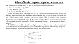
SlideShare a Scribd company logo
ROTARY COMPRESSORS
ROTARY COMPRESSORS: Classification, working principles of
Centrifugal compressor and Axial flow compressor, Surging, Choking
and Stalling. Comparison of Centrifugal and Axial compressor.
Comparison of Reciprocating and Rotary compressors. (7)
INTRODUCTION:
In a rotary compressor, the compression of air is achieved due to the
rotating blades fitted in a rotor. It requires less starting torque as compared to
reciprocating compressors because of direct coupling with the prime mover.
Usually, rotary compressors operate at high speed and supplies higher quantity of
air than reciprocating compressors.
CENTRIFUGAL COMPRESSORS:
A centrifugal compressor is of roto-dynamic type in which air flows
continuously and steadily through various parts and the rise in pressure is
primarily due to the centrifugal action. It is used to supply large quantities of air
but at a lower pressure ratio.
A centrifugal compressor consists of four elements namely, inlet buckets,
impeller, diffuser, and casing as shown in Fig. The inlet buckets are attached to the
shaft and rotate with it, which guide air on the impeller. The impeller consists of a
disc on which radial blades are attached. The diffuser surrounds the impeller and
provides diverging passages for air flow, thus increasing the air pressure. The air
coming out from the diffuser is collected in the casing and taken out from the
outlet of the compressor
WORKING PRINCIPLE:
The air enters the eye of the compressor at atmospheric pressure and low
velocity. The inlet buckets guide the air to the impeller where it moves radially
outward and is guided by the impeller blades. The impeller increases the
momentum of the air flowing through it, causing a rise in pressure, velocity and
temperature of the air. The air leaving the impeller enters the diffuser where its
velocity is reduced by providing more cross-sectional area for the flow of air. A part
of the kinetic energy of air is converted into pressure energy and further increases
the pressure of air.
VARIATION OF VELOCITY AND PRESSURE:
As the air flows through the
impeller and diffuser, there is a variation
of both velocity and pressure as shown in
Fig. Nearly half of the total pressure rise
takes place in the impeller and the
remaining half occurs in the diffuser. A
pressure ratio of 4 can be achieved in
single-stage compressors. For higher
pressure ratios, multi-stage compressors
are used. A pressure ratio of 12:1 is
possible with multi-stage compressors.
TYPES OF IMPELLERS:
Impellers are of two types—
single-eye type and double-eyed
type as shown in Fig. (a) and (b),
respectively. In a single-eye type, air
enters into the compressor from one
side only, whereas in a double-eyed
type, air enters from both sides. A
double-eyed type impeller sucks in
more air and has the advantage of
self-balancing over a single-eye
impeller.
In multi-stage compressors,
the output of the first stage is passed
on to the second stage and so on, as
shown in Fig.(c).
STATIC AND STAGNATION PROPERTIES
The velocities of air encountered in centrifugal compressors are very high as
compared to that in reciprocating compressors. Therefore, total head quantities should
be taken into account in the analysis of centrifugal compressors. The total head
quantities account for the kinetic energy of the air passing through the compressor.
Consider a horizontal passage of varying area of cross-section, as shown in Fig. ,
through which air flows from left to right. Assuming no external heat transfer and work
transfer to the system, the steady flow energy equation for one kg mass of air flow can
be written as:
Temperature T is called the ‘static temperature’; it is the temperature of the
air measured by a thermometer moving with the air velocity. If the moving air is
brought to rest under reversible adiabatic conditions, the total kinetic energy of the
air is converted into thermal energy, thereby increasing its temperature and
pressure. This temperature and pressure of the air are known as ‘stagnation’ or
‘total head’ temperature and pressure. The stagnation quantities are denoted by a
suffix notation o.
ADIABATIC AND ISENTROPIC PROCESSES
For an adiabatic compression process, there is no heat
exchange with the surroundings. If the adiabatic process is
reversible (frictionless), then the process is called isentropic
process in which the entropy of the system does not change.
However, in an actual compressor, during adiabatic compression,
there are losses due to friction in air and blade passages, eddies
formation, and shocks at entry and exit. These factors cause
internal heat generation and consequently, the maximum
temperature reached would be higher than that for adiabatic
compression. This results in a progressive increase in entropy.
Such a process, although adiabatic, is not reversible adiabatic or
isentropic.
The isentropic and adiabatic processes for the static and
stagnation values are shown in Fig. on the T-s diagram. Process
1-2 is the isentropic process for the static temperature and 01-02
for the total head temperature. Processes 1-2′ and 01-02′ are the
adiabatic processes for the static and total head temperatures,
respectively.
Isentropic Efficiency
Definition: Isentropic efficiency may be defined as the ratio of isentropic
temperature rise to actual temperature rise.
During compression process, work has to be done on the impeller. The energy
balance then gives,
COMPARISON OF CENTRIFUGAL AND RECIPROCATING COMPRESSORS
Velocity triangle Nomenclature:
Suffix ‘1’ denotes parameters at inlet and ‘2’ at
outlet.
β1 = Angle of the rotor blade at inlet
β2 = Angle of the rotor blade at outlet
α1 = Angle made by entering air or exit angle of
guide blade
α2 = Angle made by the outgoing air from rotor
blade
V1 and V2 = Absolute velocity of air at inlet and
outlet of rotor, m/s
Vr1 and Vr2 = Relative velocity of air at inlet and
outlet of rotor, m/s
Vf1 and Vf2 = Velocity of flow at inlet and outlet
of rotor, m/s
Vw1 and Vw2 = Velocity of whirl at inlet and outlet of rotor, m/s
Vb1 and Vb2 = Mean peripheral velocity of blade tip at inlet and outlet, m/s
R1 and R2 = Inner and outer radii of rotor, m
m = Mass flow rate of air, kg/s
At the inlet to rotor, air enters with absolute velocity V1 making an angle α1
to the direction of motion of blade (usually α1 = 90°), without any shock and
its whirl component Vw1 = 0.
Work Requirement (Euler’s Work) for a Centrifugal
Compressor:
The work required/kg of air in a stage of a centrifugal compressor
can be found by applying the moment of momentum theorem.
As per the Newtonian equation, force is given by rate of change of
momentum.
Similarly, rate of change of moment of momentum about the centre
of rotation gives torque.
Work Requirement (Euler’s Work) for a Centrifugal Compressor:
Different vane shape
• The impellers may be classified depending on the exit angle β2 into (i)
Backward curved vanes, (ii) Radial vanes and (iii) Forward curved
blades.
16
Slip Factor of Centrifugal Compressors:
Under ideal conditions, fluid particles follow exactly the same path
of blade profile such that relative velocity at impeller outlet tip is
inclined with the tangential direction at blade tip angle β2 only,
irrespective of mass flow rate, speed etc.
Such an ideal flow is possible when impeller has infinite number of
blades of no thickness.
In actual practice, when impeller has finite number of blades, fluid
is trapped between the impeller vanes due to its inertia and the fluid
is reluctant to flow over the impeller.
This causes a pressure difference across the blades. There is a high
pressure at the leading face and low pressure at the trailing face.
This pressure difference generates a relative velocity gradient and
formation of eddies.
The fluid is thus discharged at a certain average angle β’2 which is
less than β2.
Therefore fluid is said to have slipped with respect to impeller during
its flow across it.
Slip and Slip Co-efficient
• It is assumed that the velocities are constant over the cross sectional
area.
• But in actual practice this assumption is not correct as shown if fig,
Slip factor depends upon number of blades and is usually 0.9. It does not
reduces the efficiency but only reduces the head developed.
Pre-rotation or Pre-whirl
• We know that the velocity at inlet
have more effect on Mach number
at inlet.
• The relative velocity at the inlet
should be minimum, which
reduces the Mach number for a
given eye tip diameter.
• For a fixed eye tip diameter the
Mach number can be reduced by
providing pre-whirl at the inlet
using guide vanes.
Pressure coefficient
Effect of blade shape on impeller performance

More Related Content

What's hot

Gas Turbine and Jet propulsion
Gas Turbine and Jet propulsionGas Turbine and Jet propulsion
Gas Turbine and Jet propulsion
SLA1987
 
Gas turbines
Gas turbinesGas turbines
Gas turbines
Mani Kanth
 
Compressor and Types
Compressor and TypesCompressor and Types
Compressor and Types
Muhammad Usama
 
Centrifugal compressor
Centrifugal compressor Centrifugal compressor
Centrifugal compressor
Héctor Nguema Ondo
 
Axial Flow Compressor.
Axial Flow Compressor. Axial Flow Compressor.
Axial Flow Compressor.
Urvesh Prajapati
 
LECTURE Notes on compressor
LECTURE Notes on compressorLECTURE Notes on compressor
LECTURE Notes on compressor
Yuri Melliza
 
Belt drive. ppt
Belt drive. pptBelt drive. ppt
Belt drive. ppt
Sadia Textile
 
STEAM NOZZLES
STEAM NOZZLESSTEAM NOZZLES
STEAM NOZZLES
Vanita Thakkar
 
Centrifugal compressor
Centrifugal compressorCentrifugal compressor
Centrifugal compressor
Prasanth M
 
Reciprocating compressor
Reciprocating compressorReciprocating compressor
Reciprocating compressor
hambardikar55
 
Volumetric efficient of a compressor
Volumetric efficient of a compressorVolumetric efficient of a compressor
Volumetric efficient of a compressor
Lahiru Dilshan
 
reciprocating compressor
reciprocating compressorreciprocating compressor
reciprocating compressor
Rajesh Sharma
 
Jet propulsion
Jet propulsionJet propulsion
Jet propulsion
vishal parmar
 
Advanced Ic engines unit 1
Advanced Ic engines unit 1Advanced Ic engines unit 1
Advanced Ic engines unit 1
Ravi Rajan
 
Steam nozzle
Steam nozzleSteam nozzle
Gas turbine
Gas turbineGas turbine
Gas turbine
naphis ahamad
 
2 c industrial hydraulic circuits
2 c industrial hydraulic circuits2 c industrial hydraulic circuits
2 c industrial hydraulic circuits
Dr.R. SELVAM
 
ROTARY COMPRESSORS
ROTARY COMPRESSORSROTARY COMPRESSORS
ROTARY COMPRESSORS
Kunj Thummar
 
Reciprocating compressor
Reciprocating compressorReciprocating compressor
Reciprocating compressor
Nathan
 
DIRECTION CONTROL VALVE
DIRECTION CONTROL VALVEDIRECTION CONTROL VALVE
DIRECTION CONTROL VALVE
gopalkrishnan202
 

What's hot (20)

Gas Turbine and Jet propulsion
Gas Turbine and Jet propulsionGas Turbine and Jet propulsion
Gas Turbine and Jet propulsion
 
Gas turbines
Gas turbinesGas turbines
Gas turbines
 
Compressor and Types
Compressor and TypesCompressor and Types
Compressor and Types
 
Centrifugal compressor
Centrifugal compressor Centrifugal compressor
Centrifugal compressor
 
Axial Flow Compressor.
Axial Flow Compressor. Axial Flow Compressor.
Axial Flow Compressor.
 
LECTURE Notes on compressor
LECTURE Notes on compressorLECTURE Notes on compressor
LECTURE Notes on compressor
 
Belt drive. ppt
Belt drive. pptBelt drive. ppt
Belt drive. ppt
 
STEAM NOZZLES
STEAM NOZZLESSTEAM NOZZLES
STEAM NOZZLES
 
Centrifugal compressor
Centrifugal compressorCentrifugal compressor
Centrifugal compressor
 
Reciprocating compressor
Reciprocating compressorReciprocating compressor
Reciprocating compressor
 
Volumetric efficient of a compressor
Volumetric efficient of a compressorVolumetric efficient of a compressor
Volumetric efficient of a compressor
 
reciprocating compressor
reciprocating compressorreciprocating compressor
reciprocating compressor
 
Jet propulsion
Jet propulsionJet propulsion
Jet propulsion
 
Advanced Ic engines unit 1
Advanced Ic engines unit 1Advanced Ic engines unit 1
Advanced Ic engines unit 1
 
Steam nozzle
Steam nozzleSteam nozzle
Steam nozzle
 
Gas turbine
Gas turbineGas turbine
Gas turbine
 
2 c industrial hydraulic circuits
2 c industrial hydraulic circuits2 c industrial hydraulic circuits
2 c industrial hydraulic circuits
 
ROTARY COMPRESSORS
ROTARY COMPRESSORSROTARY COMPRESSORS
ROTARY COMPRESSORS
 
Reciprocating compressor
Reciprocating compressorReciprocating compressor
Reciprocating compressor
 
DIRECTION CONTROL VALVE
DIRECTION CONTROL VALVEDIRECTION CONTROL VALVE
DIRECTION CONTROL VALVE
 

Similar to Rotary Compressors.pptx

centrifugal compressor.pptx
centrifugal compressor.pptxcentrifugal compressor.pptx
centrifugal compressor.pptx
raviprakashsaini
 
Chapter 3 centrifugal comp
Chapter 3 centrifugal compChapter 3 centrifugal comp
Chapter 3 centrifugal comp
Novak Djokovich
 
Axial flow compressors
Axial flow compressorsAxial flow compressors
Axial flow compressors
Saif al-din ali
 
Eme (air compressors)
Eme (air compressors)Eme (air compressors)
Eme (air compressors)
Student
 
5916964.ppt
5916964.ppt5916964.ppt
5916964.ppt
M. Nazir
 
Air Compressor
Air CompressorAir Compressor
Air Compressor
Parth Patel
 
Air comprosser
Air comprosserAir comprosser
Air comprosser
RonalDinho4
 
Mueez.pptx
Mueez.pptxMueez.pptx
Mueez.pptx
MueezAalam
 
20130644
2013064420130644
Compressor and types of compressors (Thermodynamics)
Compressor and types of compressors (Thermodynamics)Compressor and types of compressors (Thermodynamics)
Compressor and types of compressors (Thermodynamics)
Hasnain Yaseen
 
Lecture-1- Compressor and its Types.ppt
Lecture-1- Compressor and its Types.pptLecture-1- Compressor and its Types.ppt
Lecture-1- Compressor and its Types.ppt
WaqasRahman10
 
Basics of Compressor
Basics of CompressorBasics of Compressor
Basics of Compressor
SLA1987
 
chaptrno-140114211033-phpapp02.pptx
chaptrno-140114211033-phpapp02.pptxchaptrno-140114211033-phpapp02.pptx
chaptrno-140114211033-phpapp02.pptx
prabhakarjha82
 
07-EC-II-Nafees P- Khan.ppt
07-EC-II-Nafees P- Khan.ppt07-EC-II-Nafees P- Khan.ppt
07-EC-II-Nafees P- Khan.ppt
DramilThakkar2
 
Air Compressor
Air CompressorAir Compressor
Air Compressor
sankarsasmal2
 
Air Compressors Operation.ppt
Air Compressors Operation.pptAir Compressors Operation.ppt
Air Compressors Operation.ppt
DPSharma12
 
Pp teme aircompressor-150514063233-lva1-app6892
Pp teme aircompressor-150514063233-lva1-app6892Pp teme aircompressor-150514063233-lva1-app6892
Pp teme aircompressor-150514063233-lva1-app6892
Akash Ladani
 
Rotary compressors ppt
Rotary compressors pptRotary compressors ppt
Reciprocating compressor and pumps
Reciprocating compressor and pumpsReciprocating compressor and pumps
Reciprocating compressor and pumps
hambardikar55
 
Fluid Mechanics and Turbo Design ch2
Fluid Mechanics and Turbo Design ch2Fluid Mechanics and Turbo Design ch2
Fluid Mechanics and Turbo Design ch2
danielmabengo
 

Similar to Rotary Compressors.pptx (20)

centrifugal compressor.pptx
centrifugal compressor.pptxcentrifugal compressor.pptx
centrifugal compressor.pptx
 
Chapter 3 centrifugal comp
Chapter 3 centrifugal compChapter 3 centrifugal comp
Chapter 3 centrifugal comp
 
Axial flow compressors
Axial flow compressorsAxial flow compressors
Axial flow compressors
 
Eme (air compressors)
Eme (air compressors)Eme (air compressors)
Eme (air compressors)
 
5916964.ppt
5916964.ppt5916964.ppt
5916964.ppt
 
Air Compressor
Air CompressorAir Compressor
Air Compressor
 
Air comprosser
Air comprosserAir comprosser
Air comprosser
 
Mueez.pptx
Mueez.pptxMueez.pptx
Mueez.pptx
 
20130644
2013064420130644
20130644
 
Compressor and types of compressors (Thermodynamics)
Compressor and types of compressors (Thermodynamics)Compressor and types of compressors (Thermodynamics)
Compressor and types of compressors (Thermodynamics)
 
Lecture-1- Compressor and its Types.ppt
Lecture-1- Compressor and its Types.pptLecture-1- Compressor and its Types.ppt
Lecture-1- Compressor and its Types.ppt
 
Basics of Compressor
Basics of CompressorBasics of Compressor
Basics of Compressor
 
chaptrno-140114211033-phpapp02.pptx
chaptrno-140114211033-phpapp02.pptxchaptrno-140114211033-phpapp02.pptx
chaptrno-140114211033-phpapp02.pptx
 
07-EC-II-Nafees P- Khan.ppt
07-EC-II-Nafees P- Khan.ppt07-EC-II-Nafees P- Khan.ppt
07-EC-II-Nafees P- Khan.ppt
 
Air Compressor
Air CompressorAir Compressor
Air Compressor
 
Air Compressors Operation.ppt
Air Compressors Operation.pptAir Compressors Operation.ppt
Air Compressors Operation.ppt
 
Pp teme aircompressor-150514063233-lva1-app6892
Pp teme aircompressor-150514063233-lva1-app6892Pp teme aircompressor-150514063233-lva1-app6892
Pp teme aircompressor-150514063233-lva1-app6892
 
Rotary compressors ppt
Rotary compressors pptRotary compressors ppt
Rotary compressors ppt
 
Reciprocating compressor and pumps
Reciprocating compressor and pumpsReciprocating compressor and pumps
Reciprocating compressor and pumps
 
Fluid Mechanics and Turbo Design ch2
Fluid Mechanics and Turbo Design ch2Fluid Mechanics and Turbo Design ch2
Fluid Mechanics and Turbo Design ch2
 

Recently uploaded

CHINA’S GEO-ECONOMIC OUTREACH IN CENTRAL ASIAN COUNTRIES AND FUTURE PROSPECT
CHINA’S GEO-ECONOMIC OUTREACH IN CENTRAL ASIAN COUNTRIES AND FUTURE PROSPECTCHINA’S GEO-ECONOMIC OUTREACH IN CENTRAL ASIAN COUNTRIES AND FUTURE PROSPECT
CHINA’S GEO-ECONOMIC OUTREACH IN CENTRAL ASIAN COUNTRIES AND FUTURE PROSPECT
jpsjournal1
 
Self-Control of Emotions by Slidesgo.pptx
Self-Control of Emotions by Slidesgo.pptxSelf-Control of Emotions by Slidesgo.pptx
Self-Control of Emotions by Slidesgo.pptx
iemerc2024
 
Building Electrical System Design & Installation
Building Electrical System Design & InstallationBuilding Electrical System Design & Installation
Building Electrical System Design & Installation
symbo111
 
Harnessing WebAssembly for Real-time Stateless Streaming Pipelines
Harnessing WebAssembly for Real-time Stateless Streaming PipelinesHarnessing WebAssembly for Real-time Stateless Streaming Pipelines
Harnessing WebAssembly for Real-time Stateless Streaming Pipelines
Christina Lin
 
Technical Drawings introduction to drawing of prisms
Technical Drawings introduction to drawing of prismsTechnical Drawings introduction to drawing of prisms
Technical Drawings introduction to drawing of prisms
heavyhaig
 
一比一原版(UMich毕业证)密歇根大学|安娜堡分校毕业证成绩单专业办理
一比一原版(UMich毕业证)密歇根大学|安娜堡分校毕业证成绩单专业办理一比一原版(UMich毕业证)密歇根大学|安娜堡分校毕业证成绩单专业办理
一比一原版(UMich毕业证)密歇根大学|安娜堡分校毕业证成绩单专业办理
zwunae
 
[JPP-1] - (JEE 3.0) - Kinematics 1D - 14th May..pdf
[JPP-1] - (JEE 3.0) - Kinematics 1D - 14th May..pdf[JPP-1] - (JEE 3.0) - Kinematics 1D - 14th May..pdf
[JPP-1] - (JEE 3.0) - Kinematics 1D - 14th May..pdf
awadeshbabu
 
原版制作(unimelb毕业证书)墨尔本大学毕业证Offer一模一样
原版制作(unimelb毕业证书)墨尔本大学毕业证Offer一模一样原版制作(unimelb毕业证书)墨尔本大学毕业证Offer一模一样
原版制作(unimelb毕业证书)墨尔本大学毕业证Offer一模一样
obonagu
 
sieving analysis and results interpretation
sieving analysis and results interpretationsieving analysis and results interpretation
sieving analysis and results interpretation
ssuser36d3051
 
Adaptive synchronous sliding control for a robot manipulator based on neural ...
Adaptive synchronous sliding control for a robot manipulator based on neural ...Adaptive synchronous sliding control for a robot manipulator based on neural ...
Adaptive synchronous sliding control for a robot manipulator based on neural ...
IJECEIAES
 
basic-wireline-operations-course-mahmoud-f-radwan.pdf
basic-wireline-operations-course-mahmoud-f-radwan.pdfbasic-wireline-operations-course-mahmoud-f-radwan.pdf
basic-wireline-operations-course-mahmoud-f-radwan.pdf
NidhalKahouli2
 
6th International Conference on Machine Learning & Applications (CMLA 2024)
6th International Conference on Machine Learning & Applications (CMLA 2024)6th International Conference on Machine Learning & Applications (CMLA 2024)
6th International Conference on Machine Learning & Applications (CMLA 2024)
ClaraZara1
 
RAT: Retrieval Augmented Thoughts Elicit Context-Aware Reasoning in Long-Hori...
RAT: Retrieval Augmented Thoughts Elicit Context-Aware Reasoning in Long-Hori...RAT: Retrieval Augmented Thoughts Elicit Context-Aware Reasoning in Long-Hori...
RAT: Retrieval Augmented Thoughts Elicit Context-Aware Reasoning in Long-Hori...
thanhdowork
 
哪里办理(csu毕业证书)查尔斯特大学毕业证硕士学历原版一模一样
哪里办理(csu毕业证书)查尔斯特大学毕业证硕士学历原版一模一样哪里办理(csu毕业证书)查尔斯特大学毕业证硕士学历原版一模一样
哪里办理(csu毕业证书)查尔斯特大学毕业证硕士学历原版一模一样
insn4465
 
Design and Analysis of Algorithms-DP,Backtracking,Graphs,B&B
Design and Analysis of Algorithms-DP,Backtracking,Graphs,B&BDesign and Analysis of Algorithms-DP,Backtracking,Graphs,B&B
Design and Analysis of Algorithms-DP,Backtracking,Graphs,B&B
Sreedhar Chowdam
 
DEEP LEARNING FOR SMART GRID INTRUSION DETECTION: A HYBRID CNN-LSTM-BASED MODEL
DEEP LEARNING FOR SMART GRID INTRUSION DETECTION: A HYBRID CNN-LSTM-BASED MODELDEEP LEARNING FOR SMART GRID INTRUSION DETECTION: A HYBRID CNN-LSTM-BASED MODEL
DEEP LEARNING FOR SMART GRID INTRUSION DETECTION: A HYBRID CNN-LSTM-BASED MODEL
gerogepatton
 
PROJECT FORMAT FOR EVS AMITY UNIVERSITY GWALIOR.ppt
PROJECT FORMAT FOR EVS AMITY UNIVERSITY GWALIOR.pptPROJECT FORMAT FOR EVS AMITY UNIVERSITY GWALIOR.ppt
PROJECT FORMAT FOR EVS AMITY UNIVERSITY GWALIOR.ppt
bhadouriyakaku
 
Modelagem de um CSTR com reação endotermica.pdf
Modelagem de um CSTR com reação endotermica.pdfModelagem de um CSTR com reação endotermica.pdf
Modelagem de um CSTR com reação endotermica.pdf
camseq
 
Advanced control scheme of doubly fed induction generator for wind turbine us...
Advanced control scheme of doubly fed induction generator for wind turbine us...Advanced control scheme of doubly fed induction generator for wind turbine us...
Advanced control scheme of doubly fed induction generator for wind turbine us...
IJECEIAES
 
Generative AI leverages algorithms to create various forms of content
Generative AI leverages algorithms to create various forms of contentGenerative AI leverages algorithms to create various forms of content
Generative AI leverages algorithms to create various forms of content
Hitesh Mohapatra
 

Recently uploaded (20)

CHINA’S GEO-ECONOMIC OUTREACH IN CENTRAL ASIAN COUNTRIES AND FUTURE PROSPECT
CHINA’S GEO-ECONOMIC OUTREACH IN CENTRAL ASIAN COUNTRIES AND FUTURE PROSPECTCHINA’S GEO-ECONOMIC OUTREACH IN CENTRAL ASIAN COUNTRIES AND FUTURE PROSPECT
CHINA’S GEO-ECONOMIC OUTREACH IN CENTRAL ASIAN COUNTRIES AND FUTURE PROSPECT
 
Self-Control of Emotions by Slidesgo.pptx
Self-Control of Emotions by Slidesgo.pptxSelf-Control of Emotions by Slidesgo.pptx
Self-Control of Emotions by Slidesgo.pptx
 
Building Electrical System Design & Installation
Building Electrical System Design & InstallationBuilding Electrical System Design & Installation
Building Electrical System Design & Installation
 
Harnessing WebAssembly for Real-time Stateless Streaming Pipelines
Harnessing WebAssembly for Real-time Stateless Streaming PipelinesHarnessing WebAssembly for Real-time Stateless Streaming Pipelines
Harnessing WebAssembly for Real-time Stateless Streaming Pipelines
 
Technical Drawings introduction to drawing of prisms
Technical Drawings introduction to drawing of prismsTechnical Drawings introduction to drawing of prisms
Technical Drawings introduction to drawing of prisms
 
一比一原版(UMich毕业证)密歇根大学|安娜堡分校毕业证成绩单专业办理
一比一原版(UMich毕业证)密歇根大学|安娜堡分校毕业证成绩单专业办理一比一原版(UMich毕业证)密歇根大学|安娜堡分校毕业证成绩单专业办理
一比一原版(UMich毕业证)密歇根大学|安娜堡分校毕业证成绩单专业办理
 
[JPP-1] - (JEE 3.0) - Kinematics 1D - 14th May..pdf
[JPP-1] - (JEE 3.0) - Kinematics 1D - 14th May..pdf[JPP-1] - (JEE 3.0) - Kinematics 1D - 14th May..pdf
[JPP-1] - (JEE 3.0) - Kinematics 1D - 14th May..pdf
 
原版制作(unimelb毕业证书)墨尔本大学毕业证Offer一模一样
原版制作(unimelb毕业证书)墨尔本大学毕业证Offer一模一样原版制作(unimelb毕业证书)墨尔本大学毕业证Offer一模一样
原版制作(unimelb毕业证书)墨尔本大学毕业证Offer一模一样
 
sieving analysis and results interpretation
sieving analysis and results interpretationsieving analysis and results interpretation
sieving analysis and results interpretation
 
Adaptive synchronous sliding control for a robot manipulator based on neural ...
Adaptive synchronous sliding control for a robot manipulator based on neural ...Adaptive synchronous sliding control for a robot manipulator based on neural ...
Adaptive synchronous sliding control for a robot manipulator based on neural ...
 
basic-wireline-operations-course-mahmoud-f-radwan.pdf
basic-wireline-operations-course-mahmoud-f-radwan.pdfbasic-wireline-operations-course-mahmoud-f-radwan.pdf
basic-wireline-operations-course-mahmoud-f-radwan.pdf
 
6th International Conference on Machine Learning & Applications (CMLA 2024)
6th International Conference on Machine Learning & Applications (CMLA 2024)6th International Conference on Machine Learning & Applications (CMLA 2024)
6th International Conference on Machine Learning & Applications (CMLA 2024)
 
RAT: Retrieval Augmented Thoughts Elicit Context-Aware Reasoning in Long-Hori...
RAT: Retrieval Augmented Thoughts Elicit Context-Aware Reasoning in Long-Hori...RAT: Retrieval Augmented Thoughts Elicit Context-Aware Reasoning in Long-Hori...
RAT: Retrieval Augmented Thoughts Elicit Context-Aware Reasoning in Long-Hori...
 
哪里办理(csu毕业证书)查尔斯特大学毕业证硕士学历原版一模一样
哪里办理(csu毕业证书)查尔斯特大学毕业证硕士学历原版一模一样哪里办理(csu毕业证书)查尔斯特大学毕业证硕士学历原版一模一样
哪里办理(csu毕业证书)查尔斯特大学毕业证硕士学历原版一模一样
 
Design and Analysis of Algorithms-DP,Backtracking,Graphs,B&B
Design and Analysis of Algorithms-DP,Backtracking,Graphs,B&BDesign and Analysis of Algorithms-DP,Backtracking,Graphs,B&B
Design and Analysis of Algorithms-DP,Backtracking,Graphs,B&B
 
DEEP LEARNING FOR SMART GRID INTRUSION DETECTION: A HYBRID CNN-LSTM-BASED MODEL
DEEP LEARNING FOR SMART GRID INTRUSION DETECTION: A HYBRID CNN-LSTM-BASED MODELDEEP LEARNING FOR SMART GRID INTRUSION DETECTION: A HYBRID CNN-LSTM-BASED MODEL
DEEP LEARNING FOR SMART GRID INTRUSION DETECTION: A HYBRID CNN-LSTM-BASED MODEL
 
PROJECT FORMAT FOR EVS AMITY UNIVERSITY GWALIOR.ppt
PROJECT FORMAT FOR EVS AMITY UNIVERSITY GWALIOR.pptPROJECT FORMAT FOR EVS AMITY UNIVERSITY GWALIOR.ppt
PROJECT FORMAT FOR EVS AMITY UNIVERSITY GWALIOR.ppt
 
Modelagem de um CSTR com reação endotermica.pdf
Modelagem de um CSTR com reação endotermica.pdfModelagem de um CSTR com reação endotermica.pdf
Modelagem de um CSTR com reação endotermica.pdf
 
Advanced control scheme of doubly fed induction generator for wind turbine us...
Advanced control scheme of doubly fed induction generator for wind turbine us...Advanced control scheme of doubly fed induction generator for wind turbine us...
Advanced control scheme of doubly fed induction generator for wind turbine us...
 
Generative AI leverages algorithms to create various forms of content
Generative AI leverages algorithms to create various forms of contentGenerative AI leverages algorithms to create various forms of content
Generative AI leverages algorithms to create various forms of content
 

Rotary Compressors.pptx

  • 1. ROTARY COMPRESSORS ROTARY COMPRESSORS: Classification, working principles of Centrifugal compressor and Axial flow compressor, Surging, Choking and Stalling. Comparison of Centrifugal and Axial compressor. Comparison of Reciprocating and Rotary compressors. (7)
  • 2. INTRODUCTION: In a rotary compressor, the compression of air is achieved due to the rotating blades fitted in a rotor. It requires less starting torque as compared to reciprocating compressors because of direct coupling with the prime mover. Usually, rotary compressors operate at high speed and supplies higher quantity of air than reciprocating compressors. CENTRIFUGAL COMPRESSORS: A centrifugal compressor is of roto-dynamic type in which air flows continuously and steadily through various parts and the rise in pressure is primarily due to the centrifugal action. It is used to supply large quantities of air but at a lower pressure ratio. A centrifugal compressor consists of four elements namely, inlet buckets, impeller, diffuser, and casing as shown in Fig. The inlet buckets are attached to the shaft and rotate with it, which guide air on the impeller. The impeller consists of a disc on which radial blades are attached. The diffuser surrounds the impeller and provides diverging passages for air flow, thus increasing the air pressure. The air coming out from the diffuser is collected in the casing and taken out from the outlet of the compressor
  • 3. WORKING PRINCIPLE: The air enters the eye of the compressor at atmospheric pressure and low velocity. The inlet buckets guide the air to the impeller where it moves radially outward and is guided by the impeller blades. The impeller increases the momentum of the air flowing through it, causing a rise in pressure, velocity and temperature of the air. The air leaving the impeller enters the diffuser where its velocity is reduced by providing more cross-sectional area for the flow of air. A part of the kinetic energy of air is converted into pressure energy and further increases the pressure of air.
  • 4.
  • 5. VARIATION OF VELOCITY AND PRESSURE: As the air flows through the impeller and diffuser, there is a variation of both velocity and pressure as shown in Fig. Nearly half of the total pressure rise takes place in the impeller and the remaining half occurs in the diffuser. A pressure ratio of 4 can be achieved in single-stage compressors. For higher pressure ratios, multi-stage compressors are used. A pressure ratio of 12:1 is possible with multi-stage compressors.
  • 6. TYPES OF IMPELLERS: Impellers are of two types— single-eye type and double-eyed type as shown in Fig. (a) and (b), respectively. In a single-eye type, air enters into the compressor from one side only, whereas in a double-eyed type, air enters from both sides. A double-eyed type impeller sucks in more air and has the advantage of self-balancing over a single-eye impeller. In multi-stage compressors, the output of the first stage is passed on to the second stage and so on, as shown in Fig.(c).
  • 7. STATIC AND STAGNATION PROPERTIES The velocities of air encountered in centrifugal compressors are very high as compared to that in reciprocating compressors. Therefore, total head quantities should be taken into account in the analysis of centrifugal compressors. The total head quantities account for the kinetic energy of the air passing through the compressor. Consider a horizontal passage of varying area of cross-section, as shown in Fig. , through which air flows from left to right. Assuming no external heat transfer and work transfer to the system, the steady flow energy equation for one kg mass of air flow can be written as:
  • 8. Temperature T is called the ‘static temperature’; it is the temperature of the air measured by a thermometer moving with the air velocity. If the moving air is brought to rest under reversible adiabatic conditions, the total kinetic energy of the air is converted into thermal energy, thereby increasing its temperature and pressure. This temperature and pressure of the air are known as ‘stagnation’ or ‘total head’ temperature and pressure. The stagnation quantities are denoted by a suffix notation o.
  • 9. ADIABATIC AND ISENTROPIC PROCESSES For an adiabatic compression process, there is no heat exchange with the surroundings. If the adiabatic process is reversible (frictionless), then the process is called isentropic process in which the entropy of the system does not change. However, in an actual compressor, during adiabatic compression, there are losses due to friction in air and blade passages, eddies formation, and shocks at entry and exit. These factors cause internal heat generation and consequently, the maximum temperature reached would be higher than that for adiabatic compression. This results in a progressive increase in entropy. Such a process, although adiabatic, is not reversible adiabatic or isentropic. The isentropic and adiabatic processes for the static and stagnation values are shown in Fig. on the T-s diagram. Process 1-2 is the isentropic process for the static temperature and 01-02 for the total head temperature. Processes 1-2′ and 01-02′ are the adiabatic processes for the static and total head temperatures, respectively.
  • 10. Isentropic Efficiency Definition: Isentropic efficiency may be defined as the ratio of isentropic temperature rise to actual temperature rise. During compression process, work has to be done on the impeller. The energy balance then gives,
  • 11. COMPARISON OF CENTRIFUGAL AND RECIPROCATING COMPRESSORS
  • 12.
  • 13. Velocity triangle Nomenclature: Suffix ‘1’ denotes parameters at inlet and ‘2’ at outlet. β1 = Angle of the rotor blade at inlet β2 = Angle of the rotor blade at outlet α1 = Angle made by entering air or exit angle of guide blade α2 = Angle made by the outgoing air from rotor blade V1 and V2 = Absolute velocity of air at inlet and outlet of rotor, m/s Vr1 and Vr2 = Relative velocity of air at inlet and outlet of rotor, m/s Vf1 and Vf2 = Velocity of flow at inlet and outlet of rotor, m/s Vw1 and Vw2 = Velocity of whirl at inlet and outlet of rotor, m/s Vb1 and Vb2 = Mean peripheral velocity of blade tip at inlet and outlet, m/s R1 and R2 = Inner and outer radii of rotor, m m = Mass flow rate of air, kg/s At the inlet to rotor, air enters with absolute velocity V1 making an angle α1 to the direction of motion of blade (usually α1 = 90°), without any shock and its whirl component Vw1 = 0.
  • 14. Work Requirement (Euler’s Work) for a Centrifugal Compressor: The work required/kg of air in a stage of a centrifugal compressor can be found by applying the moment of momentum theorem. As per the Newtonian equation, force is given by rate of change of momentum. Similarly, rate of change of moment of momentum about the centre of rotation gives torque.
  • 15. Work Requirement (Euler’s Work) for a Centrifugal Compressor:
  • 16. Different vane shape • The impellers may be classified depending on the exit angle β2 into (i) Backward curved vanes, (ii) Radial vanes and (iii) Forward curved blades. 16
  • 17. Slip Factor of Centrifugal Compressors: Under ideal conditions, fluid particles follow exactly the same path of blade profile such that relative velocity at impeller outlet tip is inclined with the tangential direction at blade tip angle β2 only, irrespective of mass flow rate, speed etc. Such an ideal flow is possible when impeller has infinite number of blades of no thickness. In actual practice, when impeller has finite number of blades, fluid is trapped between the impeller vanes due to its inertia and the fluid is reluctant to flow over the impeller. This causes a pressure difference across the blades. There is a high pressure at the leading face and low pressure at the trailing face. This pressure difference generates a relative velocity gradient and formation of eddies. The fluid is thus discharged at a certain average angle β’2 which is less than β2. Therefore fluid is said to have slipped with respect to impeller during its flow across it.
  • 18. Slip and Slip Co-efficient • It is assumed that the velocities are constant over the cross sectional area. • But in actual practice this assumption is not correct as shown if fig,
  • 19. Slip factor depends upon number of blades and is usually 0.9. It does not reduces the efficiency but only reduces the head developed.
  • 20. Pre-rotation or Pre-whirl • We know that the velocity at inlet have more effect on Mach number at inlet. • The relative velocity at the inlet should be minimum, which reduces the Mach number for a given eye tip diameter. • For a fixed eye tip diameter the Mach number can be reduced by providing pre-whirl at the inlet using guide vanes.
  • 22. Effect of blade shape on impeller performance