19 Aug 2020
Module5: 6 hrs.
Gas Power cycles:
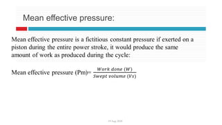
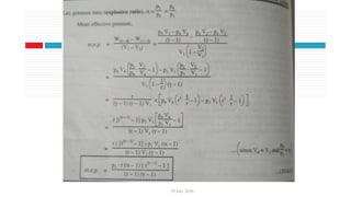
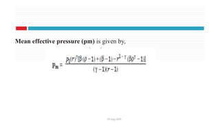
Nomenclature of a reciprocating engine, Mean effective pressure , Assumptions of
air Standard Cycle, Otto cycle, Diesel Cycle and Dual cycle, Comparison of Otto
and Diesel cycle for same compression ratio, Brayton Cycle.
Sterling Cycle, Ericsson Cycle, Lenoir cycle, and Atkinson cycle (Only theory).
CO5: Explain the fundamental principles and operations of various practical
thermodynamic cycles viz, Gas power cycles, and apply the acquired knowledge
to evaluate, interpret and compare performance parameters of this cycles used in I
C engines, Gas turbines And Jet propulsion.
5.
DEFINITION OF ACYCLE
A cycle is defined as a repeated series of operations occurring in a certain
order. It may be repeated by repeating the processes in the same order. The
cycle may be of imaginary perfect engine or actual engine. The former is
called ideal cycle and the latter actual cycle. In ideal cycle all accidental heat
losses are prevented and the working substance is assumed to behave like a
perfect working substance.
6.
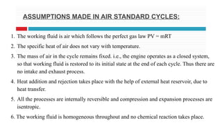
ASSUMPTIONS MADE INAIR STANDARD CYCLES:
1. The working fluid is air which follows the perfect gas law PV = mRT
2. The specific heat of air does not vary with temperature.
3. The mass of air in the cycle remains fixed. i.e., the engine operates as a closed system,
so that working fluid is restored to its initial state at the end of each cycle. Thus there are
no intake and exhaust process.
4. Heat addition and rejection takes place with the help of external heat reservoir, due to
heat transfer.
5. All the processes are internally reversible and compression and expansion processes are
isentropic.
6. The working fluid is homogeneous throughout and no chemical reaction takes place.
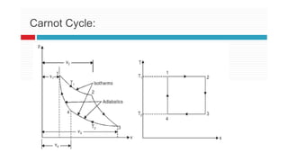
THE CARNOT CYCLE
Thiscycle has the highest possible efficiency and consists
of four simple operations namely,
(a) Isothermal expansion
(b) Adiabatic expansion
(c) Isothermal compression
(d) Adiabatic compression.
CONSTANT VOLUME OROTTO CYCLE
This cycle is so named as it was conceived by ‘Otto’. On
this cycle, petrol, gas and many types of oil engines work.
It is the standard of comparison for internal combustion
engines.
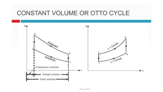
Figs. (a) and (b) shows the theoretical p-V diagram and T-s
diagrams of this cycle
19 Aug 2020
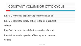
CONSTANTVOLUME OR OTTO CYCLE
Line 1-2 represents the adiabatic compression of air
Line 2-3 shows the supply of heat to the air at constant
volume
Line 3-4 represents the adiabatic expansion of the air
Line 4-1 shows the rejection of heat by air at constant
volume
19 Aug 2020
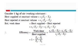
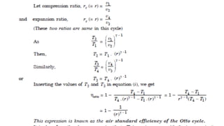
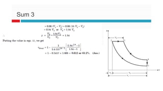
Itis clear from the above expression that efficiency increases with the increase
in the value of r, which means we can have maximum efficiency by increasing
r to a considerable extent, but due to practical difficulties its value is limited to
about 8
19 Aug 2020
Sumno 2, Gate 98
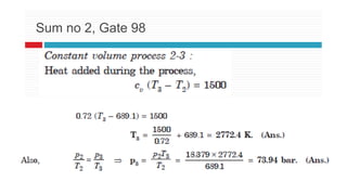
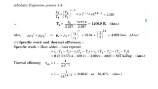
The minimum pressure and temperature in an Otto cycle are 100 kPa and
27°C. The amount of heat added to the air per cycle is 1500 kJ/kg.
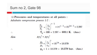
(i) Determine the pressures and temperatures at all points of the air standard
Otto cycle.
(ii) Also calculate the specific work and thermal efficiency of the cycle for a
compression
ratio of 8 : 1.
Take for air : cv = 0.72 kJ/kg K, and γ = 1.4.
26.
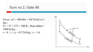
Given : p1= 100 kPa = 105 N/m2 or 1
bar ;
T1 = 27 + 273 = 300 K ; Heat added =
1500 kJ/kg ;
r = 8 : 1 ; cv = 0.72 kJ/kg ; γ = 1.4.
Sum no 2, Gate 98
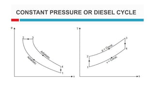
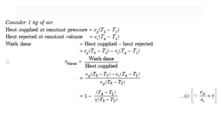
CONSTANT PRESSURE ORDIESEL CYCLE
This cycle was introduced by Dr. R. Diesel in 1897. It differs from Otto cycle
in that heat is supplied at constant pressure instead of at constant volume.
This cycle comprises of the following operations:
(i) 1-2......Adiabatic compression.
(ii) 2-3......Addition of heat at constant pressure.
(iii) 3-4......Adiabatic expansion.
(iv) 4-1......Rejection of heat at constant volume.
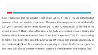
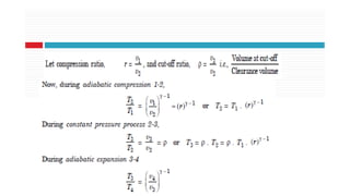
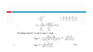
Point 1 representsthat the cylinder is full of air. Let p1, V1 and T1 be the corresponding
pressure, volume and absolute temperature. The piston then compresses the air adiabatically
(i.e., pVγ
= constant) till the values become p2, V2 and T2 respectively (at the end of the
stroke) at point 2. Heat is then added from a hot body at a constant pressure. During this
addition of heat let volume increases from V2 to V3 and temperature T2 to T3, corresponding
to point 3. This point (3) is called the point of cut-off. The air then expands adiabatically to
the conditions p4, V4 and T4 respectively corresponding to point 4. Finally, the air rejects the
heat to the cold body at constant volume till the point 1 where it returns to its original state.
19 Aug 2020
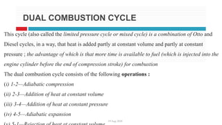
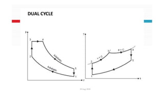
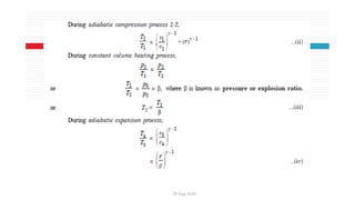
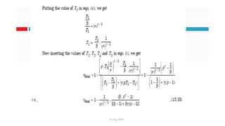
DUALCOMBUSTION CYCLE
This cycle (also called the limited pressure cycle or mixed cycle) is a combination of Otto and
Diesel cycles, in a way, that heat is added partly at constant volume and partly at constant
pressure ; the advantage of which is that more time is available to fuel (which is injected into the
engine cylinder before the end of compression stroke) for combustion
The dual combustion cycle consists of the following operations :
(i) 1-2—Adiabatic compression
(ii) 2-3—Addition of heat at constant volume
(iii) 3-4—Addition of heat at constant pressure
(iv) 4-5—Adiabatic expansion
20 Aug 2020
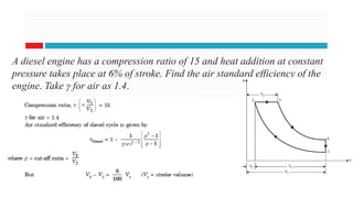
Adiesel engine has a compression ratio of 15 and heat addition at constant
pressure takes place at 6% of stroke. Find the air standard efficiency of the
engine. Take γ for air as 1.4.
19 Aug 2020
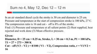
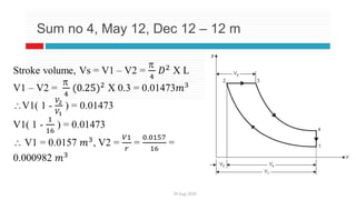
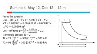
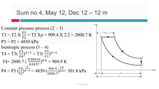
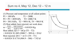
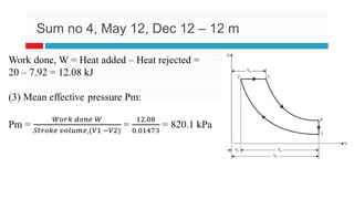
Sumno 4, May 12, Dec 12 – 12 m
In an air standard diesel cycle the stroke is 30 cm and diameter is 25 cm.
Pressure and temperature at the start of compression stroke is 100 kPa, 27˚C.
The compression ratio is 16 and cut - off is 8% of the stroke.
Find: (1) Pressure and temperature at all salient points (2) Heat supplied, heat
rejected and work done (3) Mean effective pressure.
Given:
Diameter, D = 25 cm = 0.25 m, Stroke, L = 30 cm = 0.3 m, P1 = 100 kPa,
T1 = 27 + 273 = 300 K
Cut – off (V3 – V2 ) = 8/100 ( V1 – V2), Compression ratio, r = V1/V2 =
16
201Aug 2020
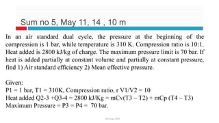
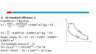
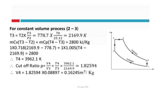
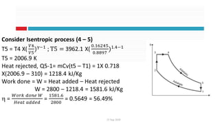
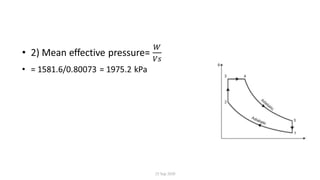
Sum no5, May 11, 14 , 10 m
In an air standard dual cycle, the pressure at the beginning of the
compression is 1 bar, while temperature is 310 K. Compression ratio is 10:1.
Heat added is 2800 kJ/kg of charge. The maximum pressure limit is 70 bar. If
heat is added partially at constant volume and partially at constant pressure,
find 1) Air standard efficiency 2) Mean effective pressure.
Given:
P1 = 1 bar, T1 = 310K, Compression ratio, r V1/V2 = 10
Heat added Q2-3 +Q3-4 = 2800 kJ/Kg = mCv(T3 – T2) + mCp (T4 – T3)
Maximum Pressure = P3 = P4 = 70 bar.
COMPARISON OF OTTO,DIESEL AND DUAL COMBUSTION CYCLES
25 Sep 2020
Following are the important variable factors which are used as a basis for
comparison of the cycles :
_ Compression ratio.
_ Maximum pressure
_ Heat supplied
_ Heat rejected
_ Net work
Some of the above mentioned variables are fixed when the performance of
Otto, Diesel and dual combustion cycles is to be compared.
25 Sep 2020
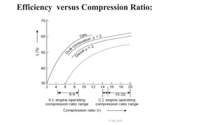
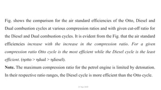
Fig.shows the comparison for the air standard efficiencies of the Otto, Diesel and
Dual combustion cycles at various compression ratios and with given cut-off ratio for
the Diesel and Dual combustion cycles. It is evident from the Fig. that the air standard
efficiencies increase with the increase in the compression ratio. For a given
compression ratio Otto cycle is the most efficient while the Diesel cycle is the least
efficient. (ηotto > ηdual > ηdiesel).
Note. The maximum compression ratio for the petrol engine is limited by detonation.
In their respective ratio ranges, the Diesel cycle is more efficient than the Otto cycle.
25 Sep 2020
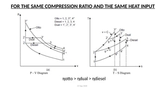
FORTHE SAME COMPRESSION RATIO AND THE SAME HEAT INPUT
P – V Diagram T – S Diagram
ηotto > ηdual > ηdiesel
66.
25 Sep 2020
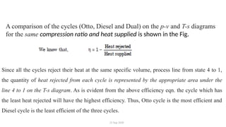
Acomparison of the cycles (Otto, Diesel and Dual) on the p-v and T-s diagrams
for the same compression ratio and heat supplied is shown in the Fig.
Since all the cycles reject their heat at the same specific volume, process line from state 4 to 1,
the quantity of heat rejected from each cycle is represented by the appropriate area under the
line 4 to 1 on the T-s diagram. As is evident from the above efficiency eqn. the cycle which has
the least heat rejected will have the highest efficiency. Thus, Otto cycle is the most efficient and
Diesel cycle is the least efficient of the three cycles.
67.
25 Sep 2020
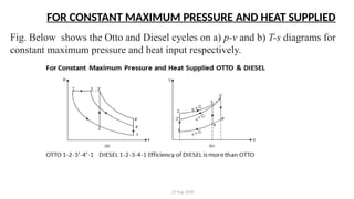
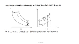
FORCONSTANT MAXIMUM PRESSURE AND HEAT SUPPLIED
Fig. Below shows the Otto and Diesel cycles on a) p-v and b) T-s diagrams for
constant maximum pressure and heat input respectively.
68.
25 Sep 2020
—For the maximum pressure the points 3 and 3′ must lie on a constant pressure
line.
— On T-s diagram the heat rejected from the Diesel cycle is represented by the
area under
the line 4 to 1 and this area is less than the Otto cycle area under the curve 4′ to 1
;
hence the Diesel cycle is more efficient than the Otto cycle for the condition of
maximum pressure and heat supplied.
25 Sep 2020
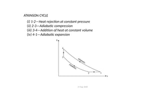
ATKINSONCYCLE
(i) 1-2—Heat rejection at constant pressure
(ii) 2-3—Adiabatic compression
(iii) 3-4—Addition of heat at constant volume
(iv) 4-1—Adiabatic expansion
71.
25 Sep 2020
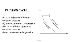
ERICSSONCYCLE
(i) 1-2—Rejection of heat at
constant pressure
(ii) 2-3—Isothermal compression
(iii) 3-4—Addition of heat at
constant pressure
(iv) 4-1—Isothermal expansion
72.
25 Sep 2020
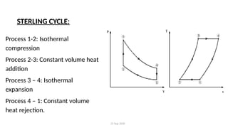
STERLINGCYCLE:
Process 1-2: Isothermal
compression
Process 2-3: Constant volume heat
addition
Process 3 – 4: Isothermal
expansion
Process 4 – 1: Constant volume
heat rejection.
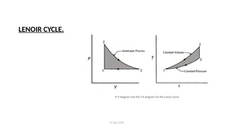
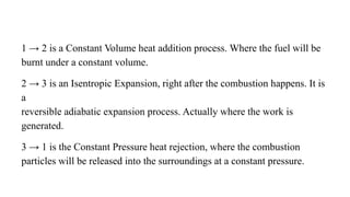
1 → 2is a Constant Volume heat addition process. Where the fuel will be
burnt under a constant volume.
2 → 3 is an Isentropic Expansion, right after the combustion happens. It is
a
reversible adiabatic expansion process. Actually where the work is
generated.
3 → 1 is the Constant Pressure heat rejection, where the combustion
particles will be released into the surroundings at a constant pressure.
75.
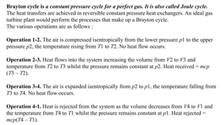
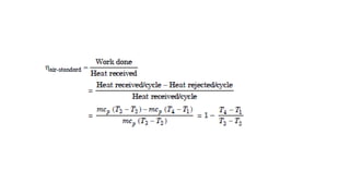
Brayton cycle isa constant pressure cycle for a perfect gas. It is also called Joule cycle.
The heat transfers are achieved in reversible constant pressure heat exchangers. An ideal gas
turbine plant would perform the processes that make up a Brayton cycle.
The various operations are as follows :
Operation 1-2. The air is compressed isentropically from the lower pressure p1 to the upper
pressure p2, the temperature rising from T1 to T2. No heat flow occurs.
Operation 2-3. Heat flows into the system increasing the volume from V2 to V3 and
temperature from T2 to T3 whilst the pressure remains constant at p2. Heat received = mcp
(T3 – T2).
Operation 3-4. The air is expanded isentropically from p2 to p1, the temperature falling from
T3 to T4. No heat flow occurs.
Operation 4-1. Heat is rejected from the system as the volume decreases from V4 to V1 and
the temperature from T4 to T1 whilst the pressure remains constant at p1. Heat rejected =
mcp(T4 – T1).
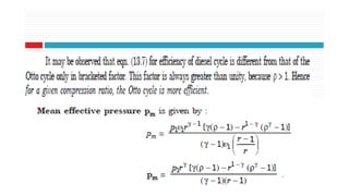
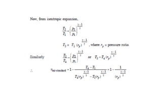
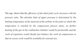
The eqn. showsthat the efficiency of the ideal joule cycle increases with the
pressure ratio. The absolute limit of upper pressure is determined by the
limiting temperature of the material of the turbine at the point at which this
temperature is reached by the compression process alone, no further
heating of the gas in the combustion chamber would be permissible and the
work of expansion would ideally just balance the work of compression so
that no excess work would be available for external use.