Download as PDF, PPTX


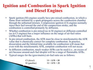
![• Brake Specific Fuel Consumption (BSFC) is a measure of fuel
efficiency within a shaft reciprocating engine. It is the rate
of fuel consumption divided by the power produced. Specific
fuel consumption is based on the torque delivered by the
engine in respect to the fuel mass flow delivered to the engine.
Measured after all parasitic engine losses is brake specific fuel
consumption [BSFC] and measuring specific fuel consumption
based on the in-cylinder pressures (ability of the pressure to do
work) is indicated specific fuel consumption [ISFC].
94](https://image.slidesharecdn.com/random-120819095427-phpapp02/85/slide-94-320.jpg)


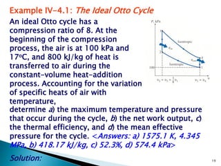
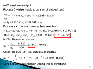
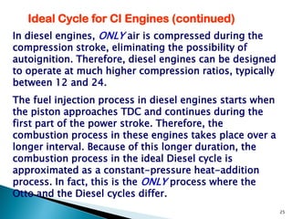
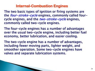
The document is an educational workbook on the basic principles of internal combustion engines. It was prepared by Engineer Nazar Faisal Ouda Al-Obaidi for the Technical Training Institute's Machinery and Equipment Department. The workbook contains information on key concepts related to internal combustion engines like: - Conversion of thermal energy to mechanical energy in heat engines through thermodynamic power cycles. - Analyzing engine cycles using pressure-volume and temperature-entropy diagrams. - Characterizing the ideal Otto cycle that models spark-ignition engines and the ideal Diesel cycle that models compression-ignition engines. - Explaining engine parameters like compression ratio, mean effective pressure, and thermal efficiency.


![DESIGN AND FABRICATION OF THE IBM 90-90 SEAT BELT CLAMP KIA VEHICLE[1].pptx 2...](https://cdn.slidesharecdn.com/ss_thumbnails/designandfabricationoftheibm90-90seatbeltclampkiavehicle1-260116160442-70ff67fc-thumbnail.jpg?width=640&height=640&fit=bounds)


