Download to read offline


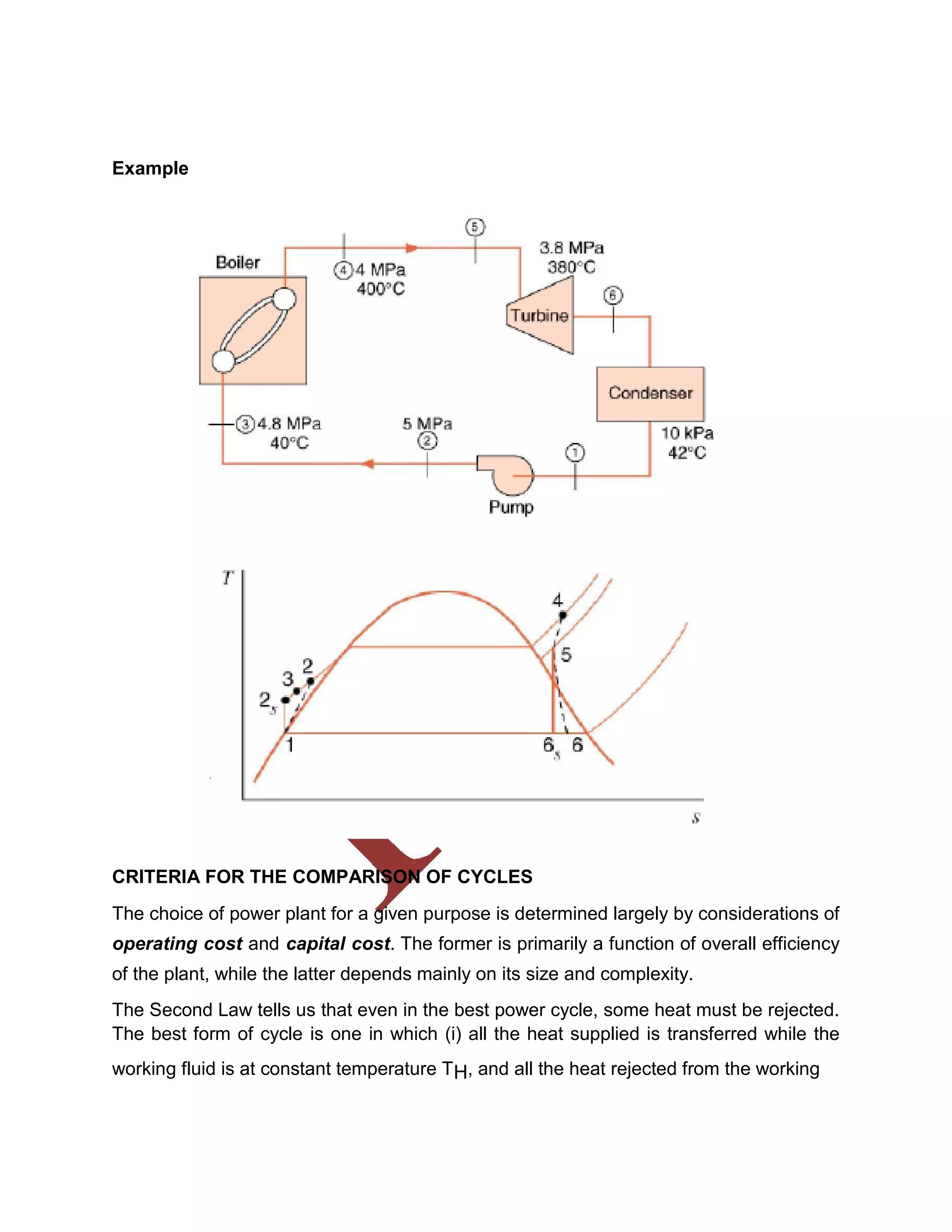
![=49
=4.49%
3. The compression ratio o f an air standard dual cycle is 12 and the maximum
pressure on the cycle is limited to 70bar. Th e pressure and temperature of the
cycle at the b eginning of compression process are 1bar a nd 300K. Calculate the
thermal efficiency and M ean Effective Pressure. Assume cylinder bore = 250mm,
Stroke length = 300mm, Cp=1.005K J/Kg K, Cv=0.718KJ/Kg K.
Given data:
Assume Qs1 = Qs2
Compression ratio (r) = 12
Maximum pressure (P3) = (P4) = 7000 KN/m2
Temperature (T1) = 300 K
Diameter (d) = 0.25m
Stroke length (l) = 0.3m
To find:
Dual cycle efficiency (ηdual)
Mean Effective Pressure (P m)
Solution:
By Process 1-2:
= [r]γ-1
300[12
T2 = 810.58K
P2 = 3242.3KN/m2](https://image.slidesharecdn.com/eded8073dpvpnotes-180418075812/75/ED8073-dpvp_notes-17-2048.jpg)
![By process 2-3:
T3 = 1750K
Assuming Qs1 = Qs2
mCv[T3-T2] = mCp[T4-T3]
0.718 [1750-810.58] = 1.005 [T4-1750] T4 = 2421.15K
By process 4-5:
We know that, = 1.38
T5 = 1019.3K](https://image.slidesharecdn.com/eded8073dpvpnotes-180418075812/75/ED8073-dpvp_notes-18-2048.jpg)
![Heat supplied Qs = 2
Q s = 1349KJ/Kg
Heat rejected
T1
]
Qr
= 516.45 KJ/Kg
ηdual
η dual = 61.72%
Stroke volume (Vs) =
Vs = 0.0147m3
Mean Effective Pressure (Pm)
= 832.58/0.0147
Pm = 56535 KN/m2
4. A diesel engine
operating
30cmstroke.the clearance volu
me is the air standard
efficiency.
an air standard
diesel cycle has
20cm bore
and
420cm3
.if the fuel is injected at
5%
of the
stroke,find
Given Data:-
Bore diameter (d) =20cm=0.2mk
Stroke, (l) =30cm=0.3m
Clearance volume, (v2 ) =420cm3
=420/1003
= m3](https://image.slidesharecdn.com/eded8073dpvpnotes-180418075812/75/ED8073-dpvp_notes-19-2048.jpg)


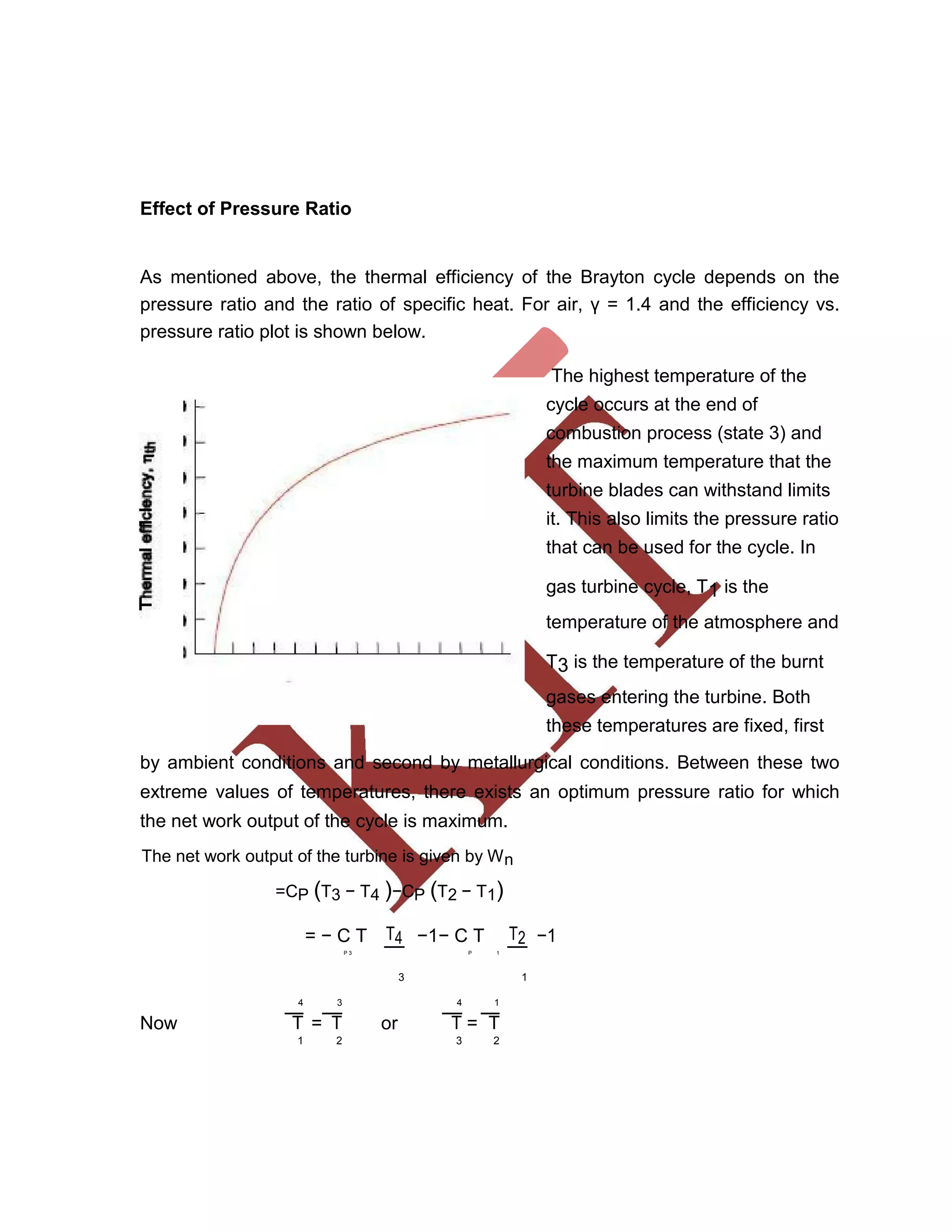
![∴ W = −C T T1 −1 − C T
T
2 −1
n P 3 P 1
2 1
γ−1
1 p2 γ
= − C T −1 − C T −1
P 3 γ−1 P 1
p
p 2 1
1
= − C T 1 −1 −C T (r ) γ
γ
−1
−1
P 3 γ−1 P 1 P
(rP ) γ
The optimum pressure ratio is obtained by differentiating the net work with respect
to pressure ratio, rP and putting the derivative as zero.
Let
γ −1
γ =n
1
Wn = −CP T3 rP n −1 −CP T1 [(rP )
n
−1]
( )
or dWn= −CP T3 [−n rP
−n−1
]−CP T1 [n rP
n−1
]
dr
P
or 0 =C T nr
−n−1
−C T n r
n−1
P 3 P P 1 P
or T nr−n−1 = T n r
n−1
3 P 1 P
or r( − n−1) − (n −1) = 1
TP
3
or r−2n = 1
P
T3
T
or r2n
=
3
P
T1
T 1
3 2n
i.e. (rP )optimum =
T
1
T3 2
γ (
γ −1
)
or (
r
P )optimum
=
T
UNIT –V
PIPING](https://image.slidesharecdn.com/eded8073dpvpnotes-180418075812/75/ED8073-dpvp_notes-71-2048.jpg)


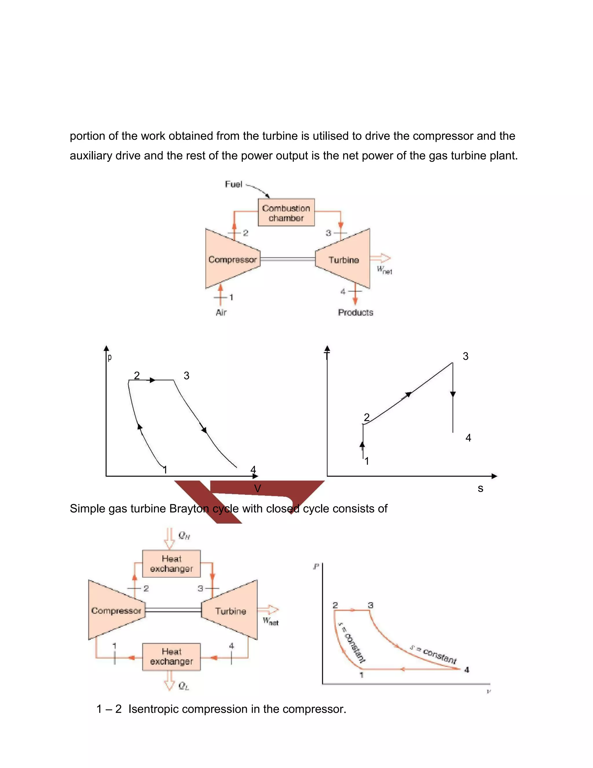
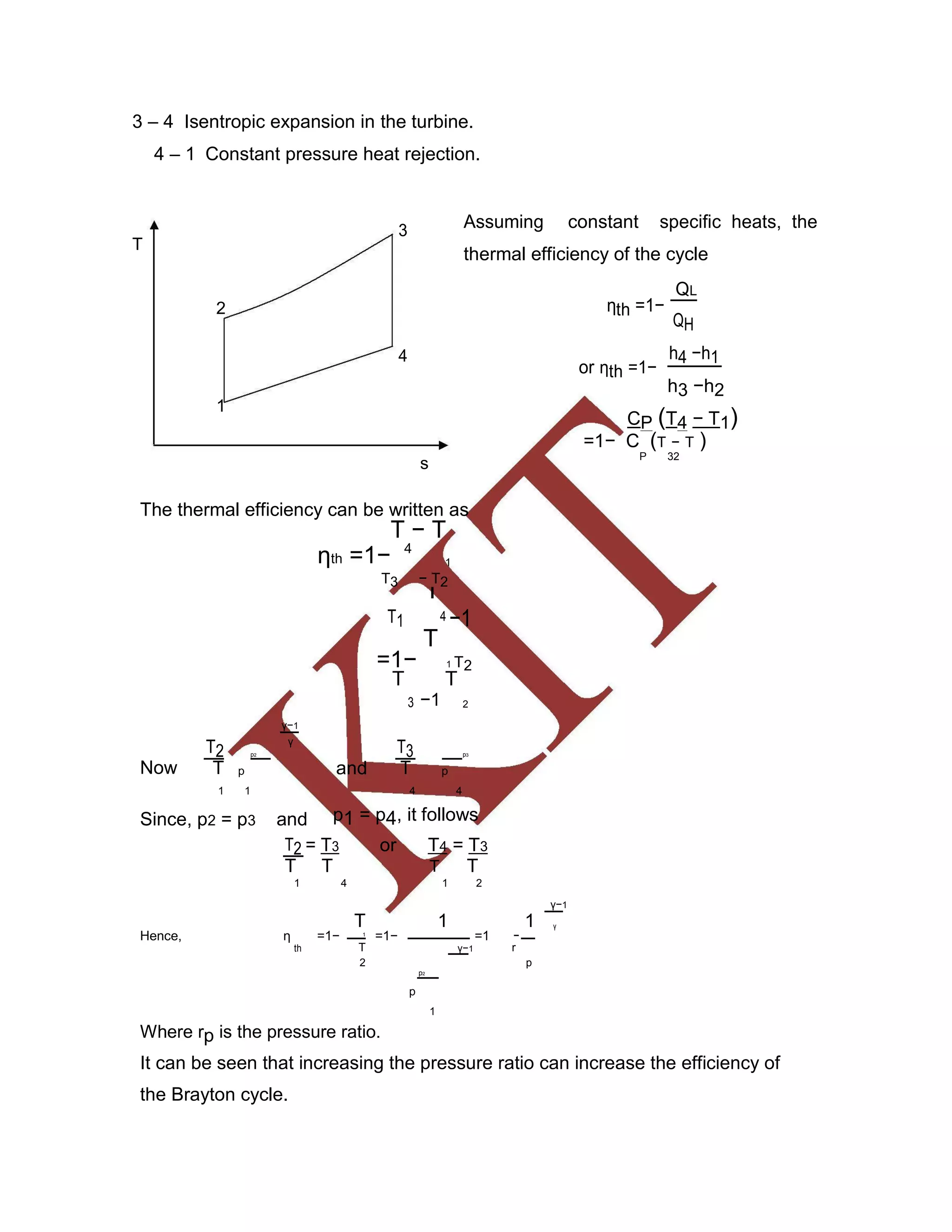
This document discusses various gas power cycles used in engines. It describes the Otto, Diesel, dual, and Brayton cycles. The Otto cycle models spark ignition engines using four processes: isentropic compression, constant volume combustion, isentropic expansion, and constant volume exhaust. The Diesel cycle also uses four processes but replaces constant volume combustion with constant pressure combustion. The dual cycle combines aspects of the Otto and Diesel cycles. The Brayton cycle models gas turbines using constant pressure processes. Real examples of engines using these cycles are also provided.