Downloaded 2,478 times
![DISPLACEMENT VOLUME
A) For single acting
VD = LD2Nn' m3/sec
4(60)
B) For Double acting without considering the volume of piston rod
VD = 2LD2Nn' m3/sec
4(60)
C) For Double acting considering volume of piston rod
VD = LNn'[2D2 - d2] m3/sec
4(60)
where: L - length of stroke, m
D - diameter of bore, m
d - diameter of piston rod, m
n' - no. of cylinders
ACTUAL VOLUMETRIC EFFICIENCY
V
ηva a x 100 %
VD
Va - actual volume of air or gas drawn in
MEAN EFFECTIVE PRESSURE
W
Pm
KPa
VD
W in KJ, KJ/kg, KW
VD in m3, m3/kg, m3/sec
PISTON SPEED
PS = 2LN m/min
PS = 2LN m/sec
60
EFFICIENCY
A) COMPRESSION EFFICIENCY
cn = Ideal Work
x 100%
Indicated Work
B) MECHANICAL EFFICIENCY
m = Indicated Work x 100%
Brake Work
C) COMPRESSOR EFFICIENCY
c = cn = m = Ideal Work x 100%
Brake work
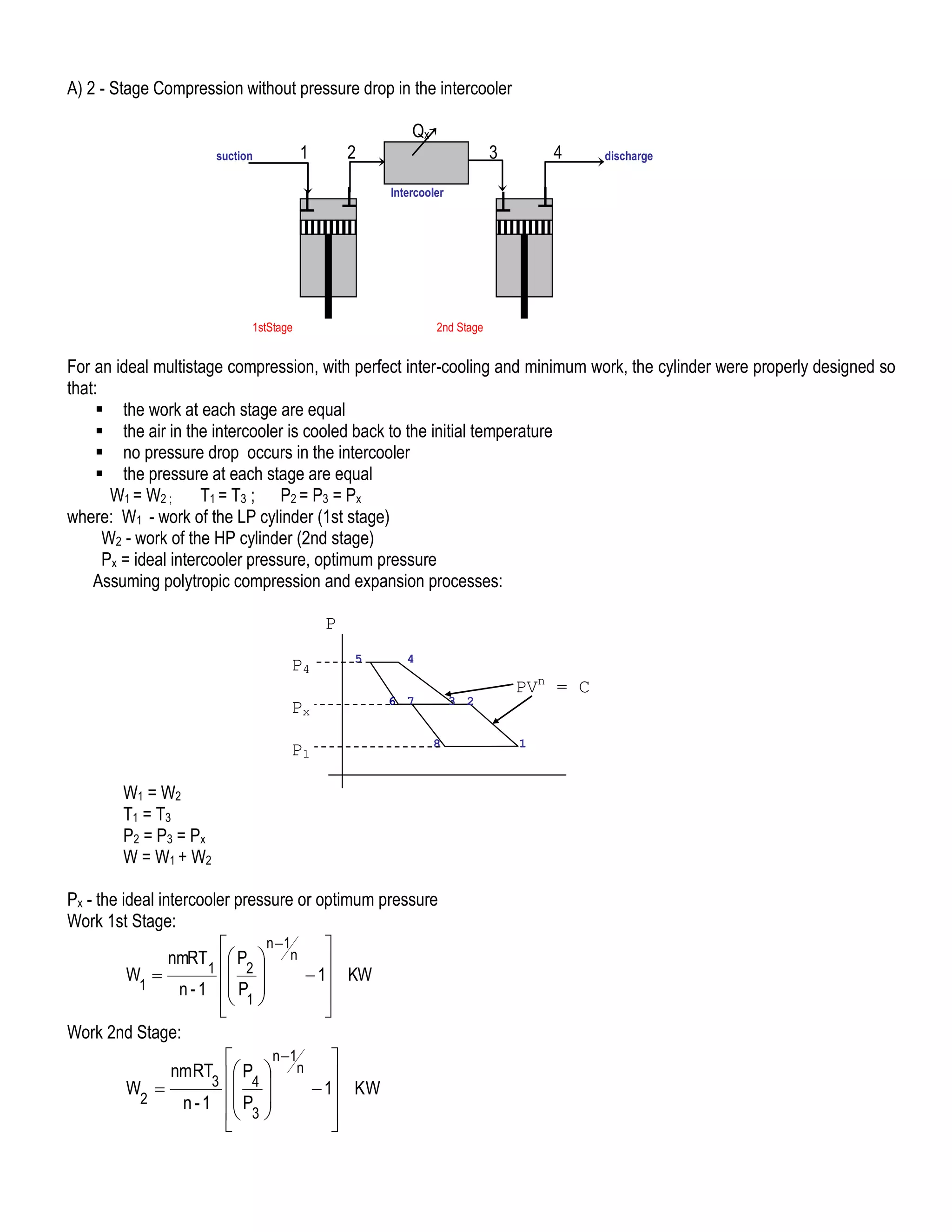
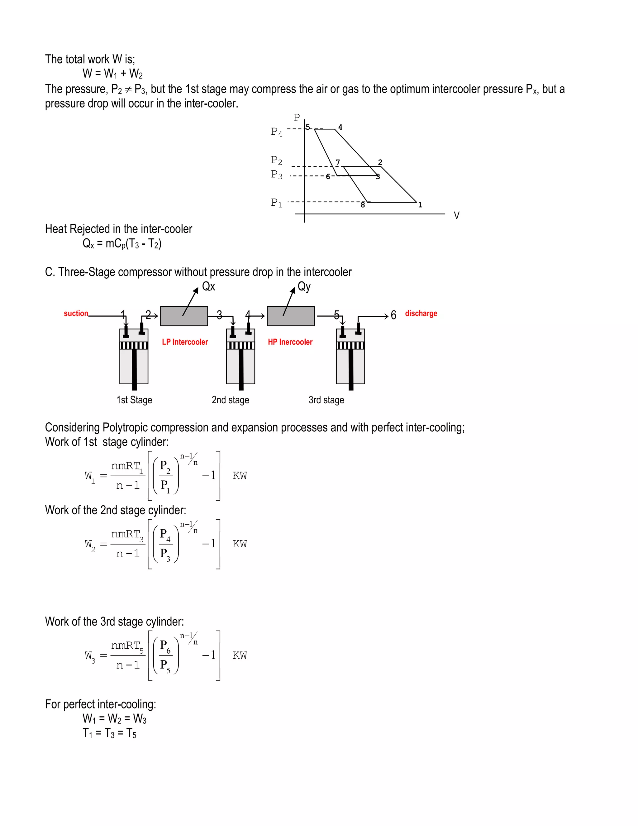
MULTISTAGE COMPRESSION
Multi staging is simply the compression of air or gas in two or more cylinders in place of a single cylinder compressor. It is
used in reciprocating compressors when pressure of 300 KPa and above are desired, in order to:
Save power
Limit the gas discharge temperature
Limit the pressure differential per cylinder
Prevent vaporization of lubricating oil and to prevent its ignition if the temperature becomes too high.
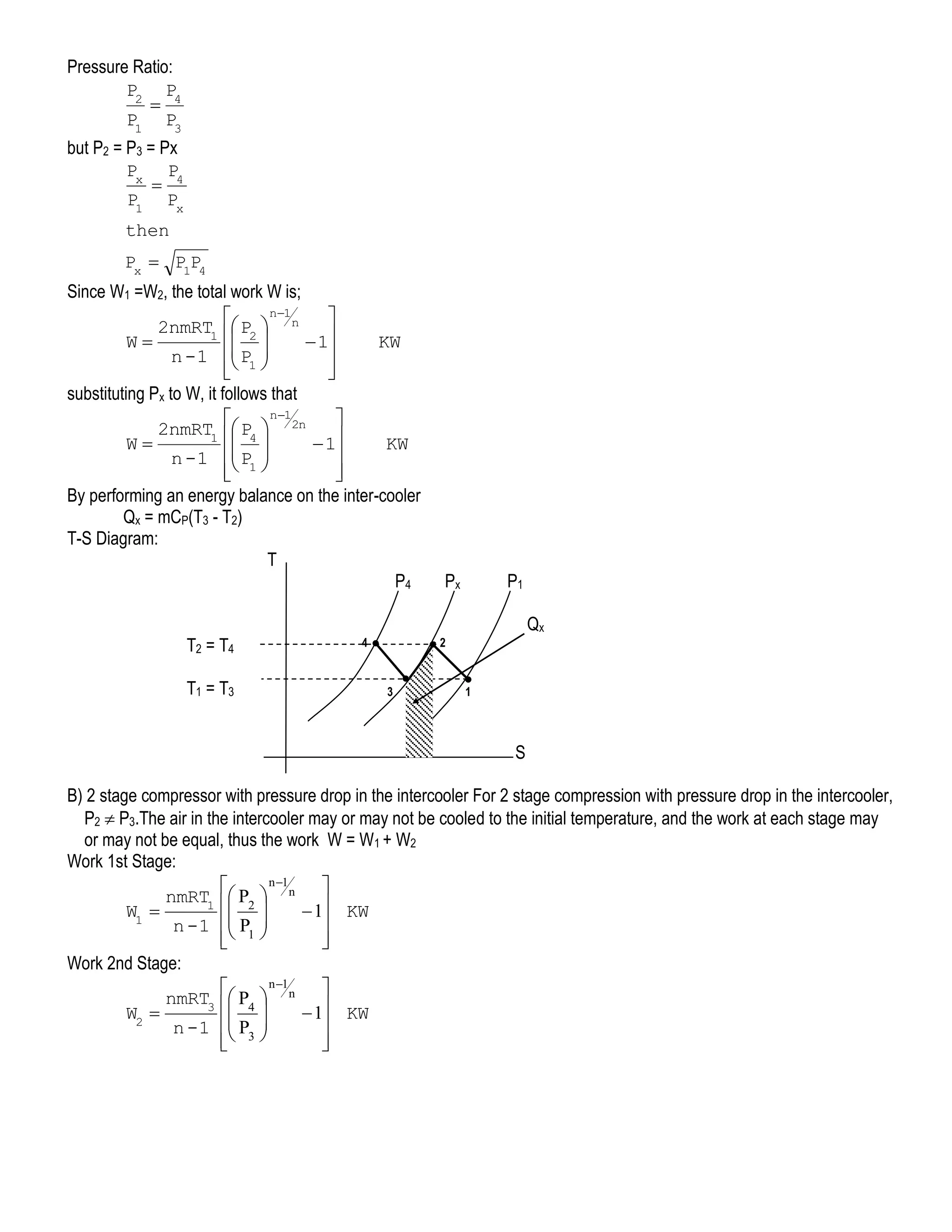
It is common practice for multi-staging to cool the air or gas between stages of compression in an intercooler, and it is this
cooling that affects considerable saving in power.](https://image.slidesharecdn.com/notesoncompressor-140208205915-phpapp02/75/LECTURE-Notes-on-compressor-5-2048.jpg)

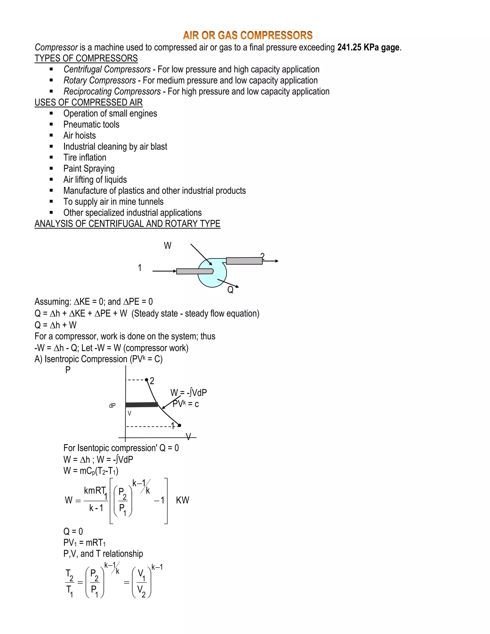
A compressor is a machine that compresses air or gas to pressures over 241.25 KPa. There are three main types: centrifugal for low pressure/high capacity, rotary for medium pressure/low capacity, and reciprocating for high pressure/low capacity. Compressed air has many industrial and specialized uses. Compressors can be analyzed using the steady flow energy equation and isentropic, polytropic, or isothermal processes. Multistage compression saves power by cooling the air between stages to limit temperature and pressure increases.


