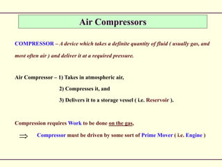
1) A compressor takes in air at atmospheric pressure and compresses it, delivering it at a higher pressure to a storage vessel.
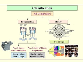
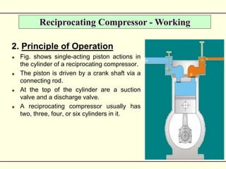
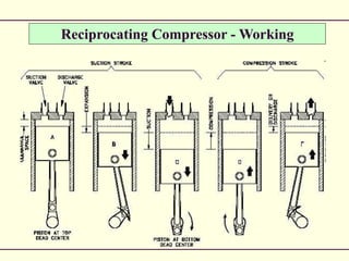
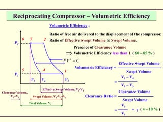
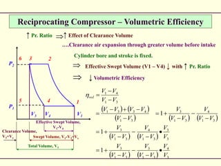
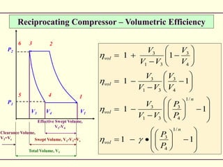
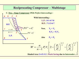
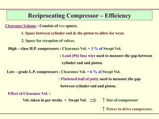
2) Reciprocating compressors use pistons driven by a crankshaft to compress air in cylinders. As the piston moves, the air is compressed and discharged from the cylinder.
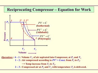
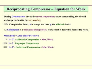
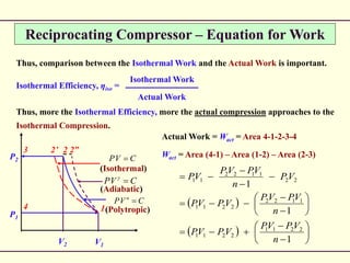
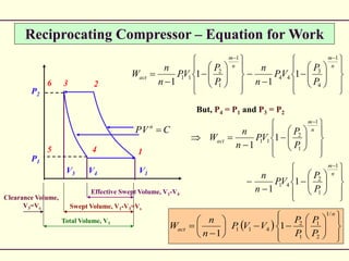
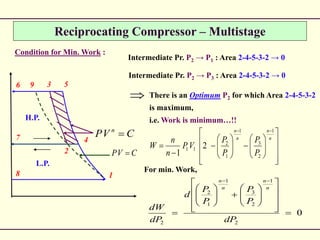
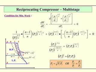
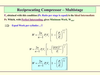
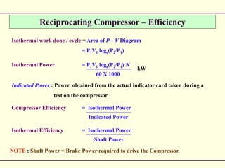
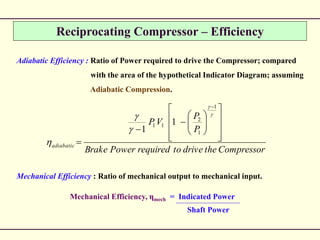
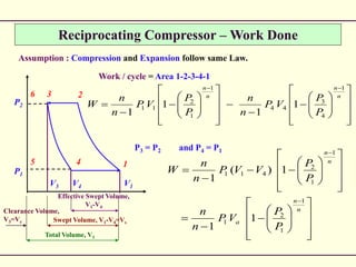
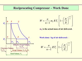
3) The work required to compress air depends on the pressure and volume changes. Actual work done is greater than theoretical isothermal work due to heat transfer during compression.
This powerpint presentation includes all the detail of various types of AIR COPMPRESSSORS,with its real and schematic diagram
- Parth Patel
1st Year Electrical
In the hydrocarbon processing and production industry, gas is compressed for transportation to consuming markets and for use in processing operations. This presentation is about the construction and operation of compressors.
In this presentation you will learn about the construction and operation of centrifugal compressors.
This PowerPoint shows an introduction to positive displacement compressors. You will have a brief introduction about the operating principles of reciprocating compressors, the different types of rotary compressors, and techniques for controlling compressor output most important variables.You will learn as well the construction, principal parts, and operation of reciprocating compressors
A steam turbine is a prime mover in which the potential energy of the steam is transformed into kinetic energy and later in its turn is transformed into the mechanical energy of rotation of the turbine shaft
Pressure Safety Valve Sizing - API 520/521/526Vijay Sarathy
No chemical process facility is immune to the risk of overpressure to avoid dictating the necessity for overpressure protection. For every situation that demands safe containment of process gas, it becomes an obligation for engineers to equally provide pressure relieving and flaring provisions wherever necessary. The levels of protection are hierarchical, starting with designing an inherently safe process to avoid overpressure followed by providing alarms for operators to intervene and Emergency Shutdown provisions through ESD and SIL rated instrumentation. Beyond these design and instrument based protection measures, the philosophy of containment and abatement steps such as pressure relieving devices, flares, physical dikes and Emergency Response Services is employed
This compressor works on the principle of centrifugal action. It finds wide variety of applications in engineering field. It is available in market from low to high capacities.
Steam ejector working principle
An ejector is a device used to suck the gas or vapour from the desired vessel or system. An ejector is similar to an of vacuum pump or compressor. The major difference between the ejector and the vacuum pump or compressor is it had no moving parts. Hence it is relatively low-cost and easy to operate and maintenance free equipment.
Compressors are mechanical devices used for increasing the pressure of a gas. Compressors used for
producing high pressure air are called air compressors. Air is drawn from the atmosphere by suction process, which is then compressed to the required pressure and delivered to the receiver
Refrigerant Compressors: Types and Numerical InsightsRavindra Kolhe
Explore the heart of refrigeration systems with this insightful presentation on refrigerant compressors. Learn about different types of compressors, their working principles, and gain practical insights through numerical examples. Whether you're a student or a professional in the field, this slide deck provides valuable knowledge in the realm of HVAC and refrigeration technology
Overview of the fundamental roles in Hydropower generation and the components involved in wider Electrical Engineering.
This paper presents the design and construction of hydroelectric dams from the hydrologist’s survey of the valley before construction, all aspects and involved disciplines, fluid dynamics, structural engineering, generation and mains frequency regulation to the very transmission of power through the network in the United Kingdom.
Author: Robbie Edward Sayers
Collaborators and co editors: Charlie Sims and Connor Healey.
(C) 2024 Robbie E. Sayers
TECHNICAL TRAINING MANUAL GENERAL FAMILIARIZATION COURSEDuvanRamosGarzon1
AIRCRAFT GENERAL
The Single Aisle is the most advanced family aircraft in service today, with fly-by-wire flight controls.
The A318, A319, A320 and A321 are twin-engine subsonic medium range aircraft.
The family offers a choice of engines
About
Indigenized remote control interface card suitable for MAFI system CCR equipment. Compatible for IDM8000 CCR. Backplane mounted serial and TCP/Ethernet communication module for CCR remote access. IDM 8000 CCR remote control on serial and TCP protocol.
• Remote control: Parallel or serial interface.
• Compatible with MAFI CCR system.
• Compatible with IDM8000 CCR.
• Compatible with Backplane mount serial communication.
• Compatible with commercial and Defence aviation CCR system.
• Remote control system for accessing CCR and allied system over serial or TCP.
• Indigenized local Support/presence in India.
• Easy in configuration using DIP switches.
Technical Specifications
Indigenized remote control interface card suitable for MAFI system CCR equipment. Compatible for IDM8000 CCR. Backplane mounted serial and TCP/Ethernet communication module for CCR remote access. IDM 8000 CCR remote control on serial and TCP protocol.
Key Features
Indigenized remote control interface card suitable for MAFI system CCR equipment. Compatible for IDM8000 CCR. Backplane mounted serial and TCP/Ethernet communication module for CCR remote access. IDM 8000 CCR remote control on serial and TCP protocol.
• Remote control: Parallel or serial interface
• Compatible with MAFI CCR system
• Copatiable with IDM8000 CCR
• Compatible with Backplane mount serial communication.
• Compatible with commercial and Defence aviation CCR system.
• Remote control system for accessing CCR and allied system over serial or TCP.
• Indigenized local Support/presence in India.
Application
• Remote control: Parallel or serial interface.
• Compatible with MAFI CCR system.
• Compatible with IDM8000 CCR.
• Compatible with Backplane mount serial communication.
• Compatible with commercial and Defence aviation CCR system.
• Remote control system for accessing CCR and allied system over serial or TCP.
• Indigenized local Support/presence in India.
• Easy in configuration using DIP switches.
COLLEGE BUS MANAGEMENT SYSTEM PROJECT REPORT.pdfKamal Acharya
The College Bus Management system is completely developed by Visual Basic .NET Version. The application is connect with most secured database language MS SQL Server. The application is develop by using best combination of front-end and back-end languages. The application is totally design like flat user interface. This flat user interface is more attractive user interface in 2017. The application is gives more important to the system functionality. The application is to manage the student’s details, driver’s details, bus details, bus route details, bus fees details and more. The application has only one unit for admin. The admin can manage the entire application. The admin can login into the application by using username and password of the admin. The application is develop for big and small colleges. It is more user friendly for non-computer person. Even they can easily learn how to manage the application within hours. The application is more secure by the admin. The system will give an effective output for the VB.Net and SQL Server given as input to the system. The compiled java program given as input to the system, after scanning the program will generate different reports. The application generates the report for users. The admin can view and download the report of the data. The application deliver the excel format reports. Because, excel formatted reports is very easy to understand the income and expense of the college bus. This application is mainly develop for windows operating system users. In 2017, 73% of people enterprises are using windows operating system. So the application will easily install for all the windows operating system users. The application-developed size is very low. The application consumes very low space in disk. Therefore, the user can allocate very minimum local disk space for this application.
Democratizing Fuzzing at Scale by Abhishek Aryaabh.arya
Presented at NUS: Fuzzing and Software Security Summer School 2024
This keynote talks about the democratization of fuzzing at scale, highlighting the collaboration between open source communities, academia, and industry to advance the field of fuzzing. It delves into the history of fuzzing, the development of scalable fuzzing platforms, and the empowerment of community-driven research. The talk will further discuss recent advancements leveraging AI/ML and offer insights into the future evolution of the fuzzing landscape.
Courier management system project report.pdfKamal Acharya
It is now-a-days very important for the people to send or receive articles like imported furniture, electronic items, gifts, business goods and the like. People depend vastly on different transport systems which mostly use the manual way of receiving and delivering the articles. There is no way to track the articles till they are received and there is no way to let the customer know what happened in transit, once he booked some articles. In such a situation, we need a system which completely computerizes the cargo activities including time to time tracking of the articles sent. This need is fulfilled by Courier Management System software which is online software for the cargo management people that enables them to receive the goods from a source and send them to a required destination and track their status from time to time.
Vaccine management system project report documentation..pdfKamal Acharya
The Division of Vaccine and Immunization is facing increasing difficulty monitoring vaccines and other commodities distribution once they have been distributed from the national stores. With the introduction of new vaccines, more challenges have been anticipated with this additions posing serious threat to the already over strained vaccine supply chain system in Kenya.
Industrial Training at Shahjalal Fertilizer Company Limited (SFCL)MdTanvirMahtab2
This presentation is about the working procedure of Shahjalal Fertilizer Company Limited (SFCL). A Govt. owned Company of Bangladesh Chemical Industries Corporation under Ministry of Industries.
Quality defects in TMT Bars, Possible causes and Potential Solutions.PrashantGoswami42
Maintaining high-quality standards in the production of TMT bars is crucial for ensuring structural integrity in construction. Addressing common defects through careful monitoring, standardized processes, and advanced technology can significantly improve the quality of TMT bars. Continuous training and adherence to quality control measures will also play a pivotal role in minimizing these defects.
Water scarcity is the lack of fresh water resources to meet the standard water demand. There are two type of water scarcity. One is physical. The other is economic water scarcity.
Student information management system project report ii.pdfKamal Acharya
Our project explains about the student management. This project mainly explains the various actions related to student details. This project shows some ease in adding, editing and deleting the student details. It also provides a less time consuming process for viewing, adding, editing and deleting the marks of the students.
2. Air Compressors
COMPRESSOR – A device which takes a definite quantity of fluid ( usually gas, and
most often air ) and deliver it at a required pressure.
Air Compressor – 1) Takes in atmospheric air,
2) Compresses it, and
3) Delivers it to a storage vessel ( i.e. Reservoir ).
Compression requires Work to be done on the gas,
Compressor must be driven by some sort of Prime Mover ( i.e. Engine )
4. Reciprocating Compressor - Working
2. Principle of Operation
Fig. shows single-acting piston actions in
the cylinder of a reciprocating compressor.
The piston is driven by a crank shaft via a
connecting rod.
At the top of the cylinder are a suction
valve and a discharge valve.
A reciprocating compressor usually has
two, three, four, or six cylinders in it.
6. Reciprocating Compressor – Equation for Work
Volume
Pressure
P1
P2
V1V2
3 2 2”2’
4 1 (Polytropic)
(Adiabatic)
(Isothermal)
CVP n
CVP
CVP
Operations : 4 – 1 : Volume V1 of air aspirated into Compressor, at P1 and T1.
1 – 2 : Air compressed according to PVn = Const. from P1 to P2.
→ Temp increase from T1 to T2.
2 – 3 : Compressed air at P2 and V2 with temperature T2 is delivered.
7. Reciprocating Compressor – Equation for Work
During Compression, due to the excess temperature above surrounding, the air will
exchange the heat to the surrounding.
Compression Index, n is always less than γ, the adiabatic index.
As Compressor is a work consuming device, every effort is desired to reduce the work.
Work done = Area under P-V curve
1 – 2” : Adiabatic Compression = Max. Work.
1 – 2 : Polytropic Compression
1 – 2’ : Isothermal Compression = Min. Work.
8. Reciprocating Compressor – Equation for Work
Thus, comparison between the Isothermal Work and the Actual Work is important.
Isothermal Efficiency, ηiso =
Isothermal Work
Actual Work
Thus, more the Isothermal Efficiency, more the actual compression approaches to the
Isothermal Compression.
P1
P2
V1V2
3 2 2”2’
4 1(Polytropic)
(Adiabatic)
(Isothermal)
CVP n
CVP
CVP
Actual Work = Wact = Area 4-1-2-3-4
Wact = Area (4-1) – Area (1-2) – Area (2-3)
1
1
1
2211
2211
1122
2211
22
1122
11
n
VPVP
VPVP
n
VPVP
VPVP
VP
n
VPVP
VP
11. Reciprocating Compressor – Equation for Work
P1
P2
V1V4
6 2
5 1
CVP n
3
4
V3
Effective Swept Volume, V1-V4
Swept Volume, V1-V3=Vs
Total Volume, V1
Clearance Volume,
V3=Vc
Clearance Volume :
Volume that remains inside the cylinder
after the piston reaches the end of its
inward stroke.
Thus, Effective Stroke Volume = V1 – V4
Actual Work = Wact = Area 1-2-3-4
Wact = Area (5-1-2-6) – Area (5-4-3-6)
12. Reciprocating Compressor – Equation for Work
n
m
n
m
act
P
P
VP
n
n
P
P
VP
n
n
W
1
1
2
41
1
1
2
11
1
1
1
1
n
act
P
P
P
P
VVP
n
n
W
/1
2
1
1
2
411 1
1
n
m
n
m
act
P
P
VP
n
n
P
P
VP
n
n
W
1
4
3
44
1
1
2
11 1
1
1
1
P1
P2
V1V4
6 2
5 1
CVP n
3
4
V3
Effective Swept Volume, V1-V4
Swept Volume, V1-V3=Vs
Total Volume, V1
Clearance Volume,
V3=Vc
But, P4 = P1 and P3 = P2
13. Reciprocating Compressor – Volumetric Efficiency
Volumetric Efficiency :
Ratio of free air delivered to the displacement of the compressor.
Ratio of Effective Swept Volume to Swept Volume.
Volumetric Efficiency =
Effective Swept Volume
Swept Volume
V1 – V4
V1 – V3
=
Vc
Vs
= = γ
Clearance Volume
Swept Volume
Clearance Ratio =
Presence of Clearance Volume
Volumetric Efficiency less than 1. ( 60 – 85 % )
P1
P2
V1V4
6 2
5 1
CVP n
3
4
V3
Effective Swept Volume, V1-V4
Swept Volume, V1-V3=Vs
Total Volume, V1
Clearance Volume,
V3=Vc
( 4 – 10 % )
14. Reciprocating Compressor – Volumetric Efficiency
↑ Pr. Ratio ↑ Effect of Clearance Volume
….Clearance air expansion through greater volume before intake
Cylinder bore and stroke is fixed.
Effective Swept Volume (V1 – V4) ↓ with ↑ Pr. Ratio
↓ Volumetric Efficiency
3
4
31
3
31
3
3
3
31
4
31
3
31
4
31
3
31
4331
31
41
1
1
1
V
V
VV
V
VV
V
V
V
VV
V
VV
V
VV
V
VV
V
VV
VVVV
VV
VV
vol
P1
P2
V1V4
6 2
5 1
3
4
V3
Effective Swept Volume,
V1-V4
Swept Volume, V1-V3=Vs
Total Volume, V1
Clearance Volume,
V3=Vc
15. Reciprocating Compressor – Volumetric Efficiency
11
11
11
11
/1
4
3
/1
4
3
31
3
4
3
31
3
4
3
31
3
n
vol
n
vol
vol
vol
P
P
P
P
VV
V
V
V
VV
V
V
V
VV
V
P1
P2
V1V4
6 2
5 1
3
4
V3
Effective Swept Volume,
V1-V4
Swept Volume, V1-V3=Vs
Total Volume, V1
Clearance Volume,
V3=Vc
16. Reciprocating Compressor – Actual P-V Diagram
P1
P2
2
1
3
4
Valve Bounce
Intake Depression
Atmospheric Pressure
Receiver Pressure 1-2-3-4-1 : Theoretical P-V Diagram.
At 4, inlet valve does not open due to :
1. There must be a pressure difference across the valve to open.
2. Inlet valve inertia.
Pr. Drop continues till sufficient level
for valve to force its seat.
Some valve bounce is set (wavy line).
Eventually, the pressure sets down at a level lower
than atmospheric pressure. This negative pressure
difference is known as Intake Depression.
Similar situation appears at 2, i.e. at the start of the delivery.
Pressure rise, followed by valve bounce and then pressure settles at a level higher than
the delivery pressure level.
Air delivery to a tank / receiver, hence, generally known as Receiver Pressure.
17. Reciprocating Compressor – F.A.D.
Free Air Delivery (F.A.D.) : If the volume of the air compressor is reduced to atmospheric
temperature and pressure, this volume of air is called FAD (m3/min)
Delivered mass of air = intake mass of air
2
322
1
411
T
VVP
T
VVP
T
VP
t
tt
If clearance volume is neglected
Where
KCT
mKNP
t
t
28815
/325.101
0
2
2
22
1
11
T
VP
T
VP
T
VP
t
tt
18. Reciprocating Compressor – Multistage
High Pressure required by Single – Stage :
1. Requires heavy working parts.
2. Has to accommodate high pressure ratios.
3. Increased balancing problems.
4. High Torque fluctuations.
5. Requires heavy Flywheel installations.
This demands for MULTI – STAGING…!!
19. Reciprocating Compressor – Multistage
Series arrangement of cylinders, in which the compressed air from earlier cylinder
(i.e. discharge) becomes the intake air for the next cylinder (i.e. inlet).
Intercooler :
Compressed air is cooled
between cylinders.
L.P. = Low Pressure
I.P. = Intermediate
Pressure
H.P. = High Pressure
L.P.
Cylinder
I.P.
Cylinder
H.P.
Cylinder
Intercooler
Intercooler
Air Intake
Air Delivery
20. Reciprocating Compressor – Multistage
Intake Pr.
P1 or Ps
Delivery Pr.
P3 or Pd
3
2
9 5
4
1
CVP n
8
7
6
Intermediate Pr.
P2 CVP
Without Intercooling
Perfect Intercooling
L.P.
H.P.
Volume
Overall Pr. Range : P1 – P3
Single – stage cycle : 8-1-5-6
Without Intercooling :
L.P. : 8-1-4-7
H.P. : 7-4-5-6
With Intercooling :
L.P. : 8-1-4-7
H.P. : 7-2-3-6
Perfect Intercooling : After initial compression in L.P. cylinder, air is cooled in the
Intercooler to its original temperature, before entering H.P. cylinder
i.e. T2 = T1 OR
Points 1 and 2 are on SAME Isothermal line.
21. Reciprocating Compressor – Multistage
Ideal Conditions for Multi – Stage Compressors :
A. Single – Stage Compressor :
CVP
3
2
9 5
4
1
CVP n
8
7
6
L.P.
H.P.
Single – stage cycle : 8-1-5-6
1
1
5
11 1
1
n
n
P
P
VP
n
n
W
Delivery Temperature,
n
n
P
P
TT
1
1
5
15
22. Reciprocating Compressor – Multistage
CVP
3
2
9 5
4
1
CVP n
8
7
6
L.P.
H.P.
B. Two – Stage Compressor (Without Intercooling) :
Without Intercooling :
L.P. : 8-1-4-7
H.P. : 7-4-5-6
n
n
n
n
P
P
VP
n
n
P
P
VP
n
n
W
1
4
5
44
1
1
4
11
1
1
1
1
This is SAME as that of Work done in Single – Stage.
Delivery Temperature also remains SAME.
Without Intercooling
23. Reciprocating Compressor – Multistage
CVP
3
2
9 5
4
1
CVP n
8
7
6
L.P.
H.P.
C. Two – Stage Compressor (With Perfect Intercooling) :
With Intercooling :
L.P. : 8-1-4-7-8
H.P. : 7-2-3-6-7
n
n
n
n
P
P
VP
n
n
P
P
VP
n
n
W
1
2
3
22
1
1
4
11
1
1
1
1
Delivery Temperature,
12
1
2
3
1
1
2
3
23 , TTas
P
P
T
P
P
TT
n
n
n
n
24. Reciprocating Compressor – Multistage
CVP
3
2
9 5
4
1
CVP n
8
7
6
L.P.
H.P.
C. Two – Stage Compressor (With Perfect Intercooling) :
With Intercooling :
L.P. : 8-1-4-7-8
H.P. : 7-2-3-6-7
n
n
n
n
P
P
P
P
VP
n
n
W
1
2
3
1
1
2
11 2
1
Now, T2 = T1
P2V2 = P1V1
Also P4 = P2
Shaded Area 2-4-5-3-2 : Work Saving due to Intercooler…!!
25. Reciprocating Compressor – Multistage
Condition for Min. Work :
CVP
3
2
9 5
4
1
CVP n
8
7
6
L.P.
H.P.
Intermediate Pr. P2 → P1 : Area 2-4-5-3-2 → 0
Intermediate Pr. P2 → P3 : Area 2-4-5-3-2 → 0
There is an Optimum P2 for which Area 2-4-5-3-2
is maximum,
i.e. Work is minimum…!!
n
n
n
n
P
P
P
P
VP
n
n
W
1
2
3
1
1
2
11 2
1
0
2
1
2
3
1
1
2
2
dP
P
P
P
P
d
dP
dW
n
n
n
n
For min. Work,
26. Reciprocating Compressor – Multistage
Condition for Min. Work :
0
111 1
1
2
1
3
1
1
21
1
n
n
n
n
n
n
n
n
P
n
n
PP
n
n
P
0
2
1
2
3
1
1
2
2
dP
P
P
P
P
d
dP
dW
n
n
n
n
n
n
n
n
n
PP
P
P 1
3112
2
/1
2
31
2
2 PPP
2
3
1
2
312
P
P
P
P
ORPPP
CVP
3
2
9 5
4
1
CVP n
8
7
6
L.P.
H.P.
27. Reciprocating Compressor – Multistage
P2 obtained with this condition (Pr. Ratio per stage is equal) is the Ideal Intermediate
Pr. Which, with Perfect Intercooling, gives Minimum Work, Wmin.
n
n
P
PP
VP
n
n
W
1
1
2/1
31
11 1
1
2
n
n
P
P
VP
n
n
W
1
1
2
11 1
1
2
n
n
P
P
VP
n
n
W
2
1
1
3
11 1
1
2
Equal Work per cylinder…!!
28. Reciprocating Compressor – Efficiency
Isothermal work done / cycle = Area of P – V Diagram
= P1V1 loge(P2/P1)
Isothermal Power = P1V1 loge(P2/P1) N
60 X 1000
kW
Indicated Power : Power obtained from the actual indicator card taken during a
test on the compressor.
Compressor Efficiency = Isothermal Power
Indicated Power
Isothermal Efficiency = Isothermal Power
Shaft Power
NOTE : Shaft Power = Brake Power required to drive the Compressor.
29. Reciprocating Compressor – Efficiency
Adiabatic Efficiency : Ratio of Power required to drive the Compressor; compared
with the area of the hypothetical Indicator Diagram; assuming
Adiabatic Compression.
CompressorthedrivetorequiredPowerBrake
P
P
VP
adiabatic
1
1
2
11 1
1
Mechanical Efficiency : Ratio of mechanical output to mechanical input.
Mechanical Efficiency, ηmech = Indicated Power
Shaft Power
30. Reciprocating Compressor – Efficiency
How to Increase Isothermal Efficiency ?
A. Spray Injection : Assimilation of water into the compressor cylinder towards the
compression stroke.
Object is to cool the air for next operation.
Demerits : 1. Requires special gear for injection.
2. Injected water interferes with the cylinder lubrication.
3. Damage to cylinder walls and valves.
4. Water must be separated before delivery of air.
B. Water Jacketing : Circulating water around the cylinder to help for cooling the
air during compression.
31. Reciprocating Compressor – Efficiency
How to Increase Isothermal Efficiency ?
C. Inter – Cooling : For high speed and high Pr. Ratio compressors.
Compressed air from earlier stage is cooled to its original
temperature before passing it to the next stage.
D. External Fins : For small capacity compressors, fins on external surfaces are useful.
E. Cylinder Proportions : Short stroke and large bore provides much greater surface
for cooling.
Cylinder head surface is far more effective than barrel surface.
32. Reciprocating Compressor – Efficiency
Clearance Volume : Consists of two spaces.
1. Space between cylinder end & the piston to allow for wear.
2. Space for reception of valves.
High – class H.P. compressors : Clearance Vol. = 3 % of Swept Vol.
: Lead (Pb) fuse wire used to measure the gap between
cylinder end and piston.
Low – grade L.P. compressors : Clearance Vol. = 6 % of Swept Vol.
: Flattened ball of putty used to measure the gap
between cylinder end and piston.
Effect of Clearance Vol. :
Vol. taken in per stroke < Swept Vol. ↑ Size of compressor
↑ Power to drive compressor.
33. P1
P2
V1V4
6 2
5 1
3
4
V3
Effective Swept Volume,
V1-V4
Swept Volume, V1-V4=Vs
Total Volume, V1
Clearance Volume,
V3=Vc
Reciprocating Compressor – Work Done
n
n
n
n
P
P
VP
n
n
P
P
VP
n
n
W
1
4
3
44
1
1
2
11 1
1
1
1
Assumption : Compression and Expansion follow same Law.
Work / cycle = Area 1-2-3-4-1
P3 = P2 and P4 = P1
n
n
a
n
n
P
P
VP
n
n
P
P
VVP
n
n
W
1
1
2
1
1
1
2
411
1
1
1)(
1
34. P1
P2
V1V4
6 2
5 1
3
4
V3
Effective Swept Volume,
V1-V4
Swept Volume, V1-V4=Vs
Total Volume, V1
Clearance Volume,
V3=Vc
Reciprocating Compressor – Work Done
n
n
P
P
TRm
n
n
W
1
1
2
11 1
1
m1 is the actual mass of air delivered.
Work done / kg of air delivered :
n
n
P
P
TR
n
n
W
1
1
2
1 1
1