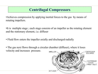
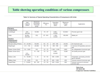
1) The document discusses air compressors, including their classification and operation of reciprocating compressors. It defines an air compressor as a device that takes in atmospheric air, compresses it, and delivers it at higher pressure to a storage vessel.
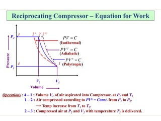
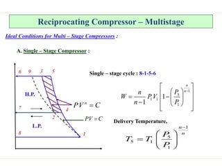
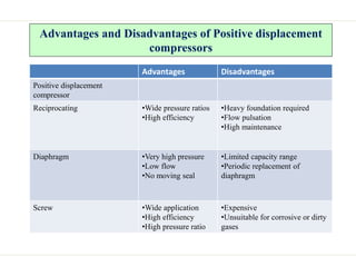
2) Reciprocating compressors use pistons driven by a crankshaft to compress gases. The intake air enters the cylinder and gets compressed by the reciprocating piston, increasing in pressure and temperature.
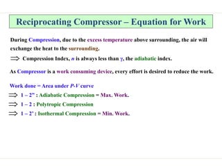
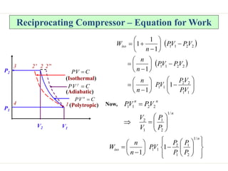
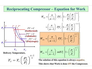
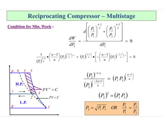
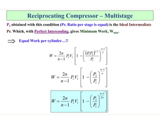
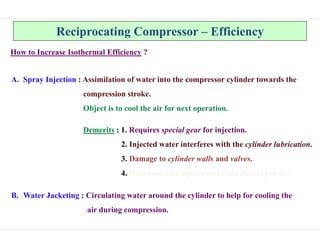
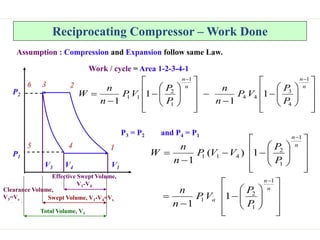
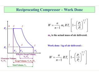
3) Equations are provided for calculating the work done by the compressor during polytropic and isothermal compression processes. The actual work done is always greater than the minimum isothermal work due to heat transfer limitations.