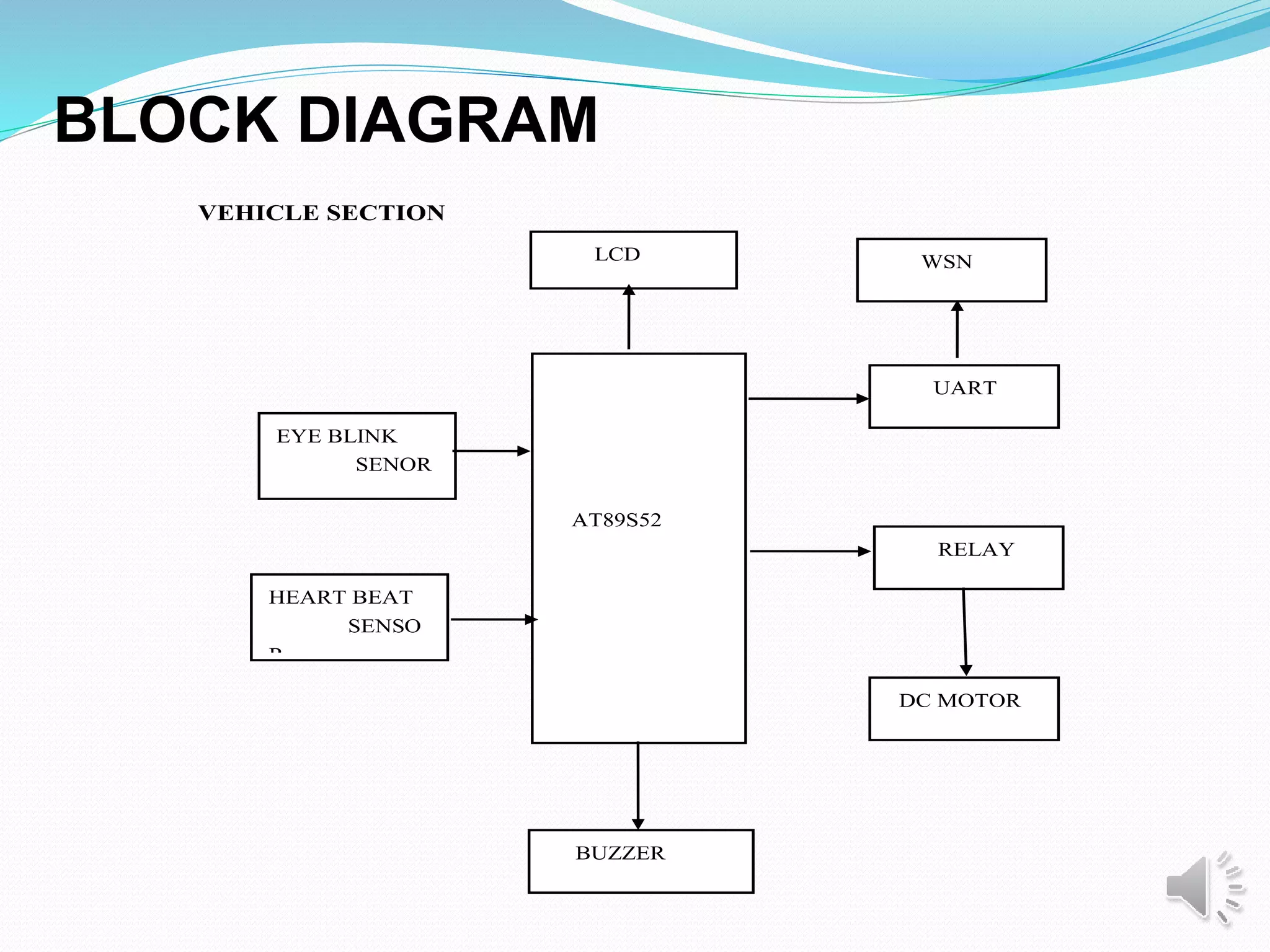
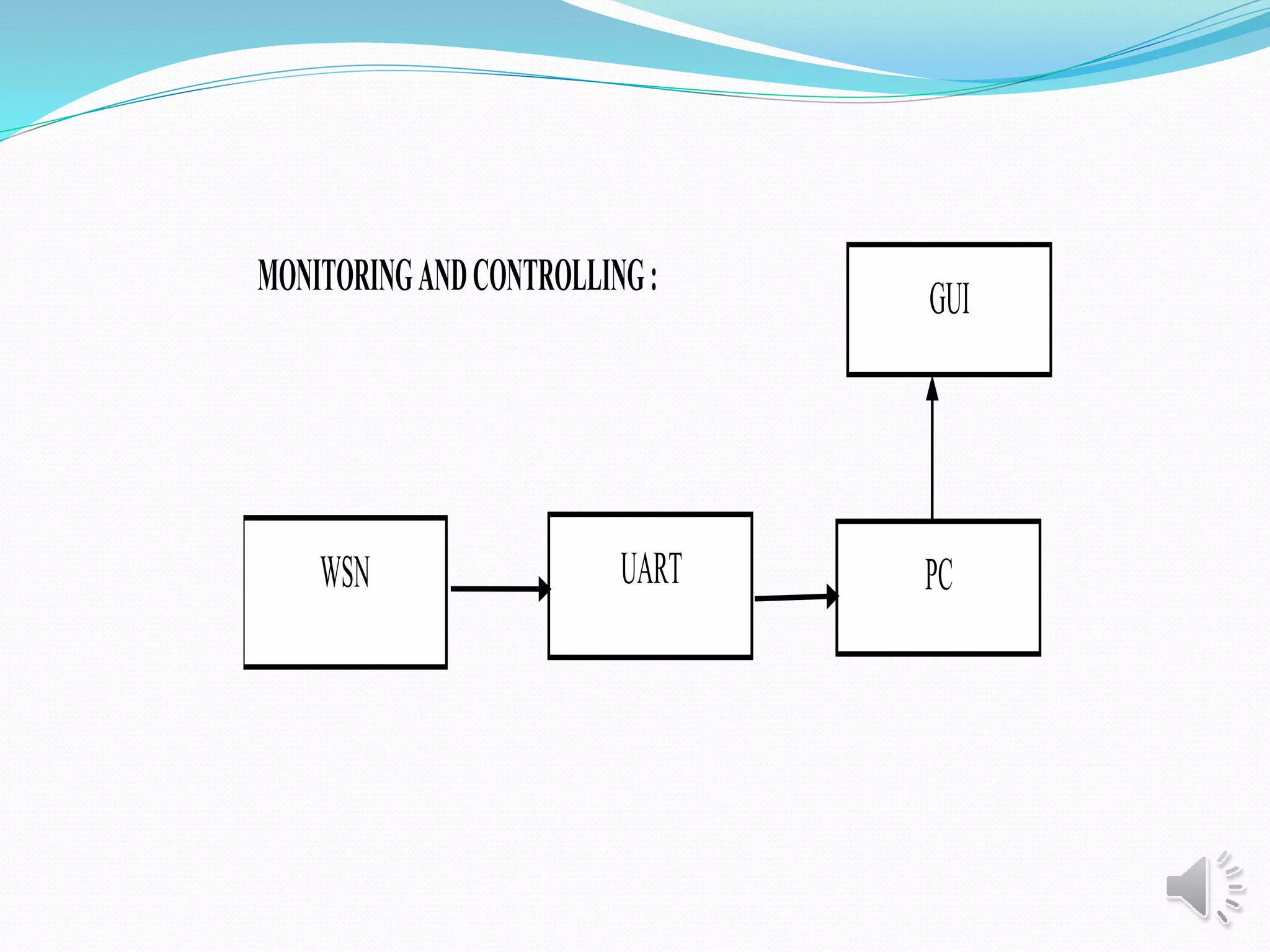
ACCIDENT PREVENTION IN VEHICLE WITH
EFFECTIVE RESCUE OPERATION
PRESENTES BY:
R.YOGALAKSHMI (VH 5021)
M.H.MEHAJABEEN (VH 5012)
R.ANUSUYA (VH 5054)
GUIDE :
K.KARTHICK (ASST PROF CSE)
 Accidents are increasing at a large pace , and various
technologies are being introduced to reduce the accidents.
Accidents due to drowsiness ,increased stress level and
sudden heart attack are prevented and controlled when
the vehicle is out of control. In this project ,we provide
accident prevention using different sensor simulation
where as the vehicle is stopped slowly an driver status is
transmitted to nearby hospital(using GPS technology) for
immediate rescue operation.
ABSTRACT
LITERATURE SURVEY
STEERING ASSIST CONTROL SYSTEM ON CURVED
ROAD USING CAR-TO-CAR COMMUNICATION
In this paper, we assume that there is a lead vehicle
in front of the host vehicle within the detection range of the
car-mounted sensor and it can detect its relative position.
First, a virtual road boundary estimation method is
proposed based on measurement of the relative position of
the lead vehicle and the lead vehicle status obtained by the
car-to-car communication method.
AUTHOR NAME: Masahiro Doi, Kai Zeng, Takahiro Wada
(Member, IEEE), Shun’ichi Doi,Naohiko Tsuru , Kazuyoshi
Isaji , Shou Morikawa
CONCEPTUALIZING ROAD SAFETY MANAGEMENT
THROUGH COMPLEX TERRITORIALIZED SYSTEMS:
The methodology used in the ANR CRITERION
program merges both interdisciplinary and multi-stake
holder objectives based on an information system that
combines approaches formalized by scientists and experts
in the field. The tool provides a user-friendly mapping
formulation of the opinions and conclusions of the partners
highlighting the possible correlations between forms and
characteristics of the area, road safety measures, accidents
and the infrastructure observed in the field. It makes it
possible to identify, specialize, qualify and compare the
areas to be processed.
AUTHOR NAME: Thierry Saint-Gérand, Mohand Medjkane,
Abdelkrim Bensaid, D. Fleury, JF. Peytavin
INTRODUCTION
 Vehicle accidents are common if the driving is inadequate
These happen on most factors if the driver is drowsy or
stressed or physically sick(low heart beat level).
 Driver drowsiness & sudden physical problem is an
important factor in the vehicle accidents . It was
demonstrated that driving performance deteriorates with
increased drowsiness with resulting crashes constituting
more than 20% of all vehicle accidents.
 This project involves measure and control the eye blink
rate, stress level & heart beat level using different sensor
And The output of the sensors are cumulated to transmit
driver status to server(i.e. nearby hospital)
 In existing system is provided with A majority of
respondents supported laws that banned talking on
cell phones, texting, or emailing while driving. Driver
should turn on the mobile application while driving the
concepts include an approach where the caller is
notified of the recipient's situation.
 The system continuously monitoring the obstacles on
speed of the vehicle and If any variations occur then
the petrol supply to the fuel motor is stopped and the
vehicle slow down.
EXISTING SYSTEM
DISADVANTAGE OF EXISTING SYSTEM
 Driver wasn't turn on the app majorly.
 Wrong information may occur.
 System continuously monitors obstacles on the road and
speed of the vehicle by using multiple sensors
 The one major advantage of proposed system is that
the sensor not only helps in stopping the vehicle,
It also sends an notification to the nearest hospitals
server side system using Wireless Sensor Network.
PROPOSED SYSTEM
ADVANTAGE OF PROPOSED SYSTEM
 Ensures Smooth driving.
 Avoid road accident.
 Ensures efficient rescue operation.
Accident controlling system
Vehicle security system
APPLICATION
 Eye ball sensor(IR SENSOR)
 Heart beat sensor(PULSE OXIMETER SENSOR)
Power supply
 Liquid crystal Display(LCD)
Micro controller(AT89S52)
Wireless Sensor Network(WSN)
Buzzer
Universal Asynchronous Receiver/Transmitter(UART)
Relay
DC Motor
HARDWARE REQUIREMENTS
Kiel compiler
Visual basic 6.0
SOFTWARE REQUIREMENTS
VEHICLE SECTION
AT89S52
LCD
BUZZER
RELAY
WSN
DC MOTOR
UART
EYE BLINK
SENOR
HEART BEAT
SENSO
R
BLOCK DIAGRAM
MONITORINGANDCONTROLLING:
WSN
GUI
PCUART
Module 1: Program analysis and interfacing with LCD
Module 2: Hardware Analysis
Module 3: Circuit Diagram and Interface Unit
Module 4: Displaying Driver Status in VB application
MODULES
MODULE 1:Program analysis and interfacing with LCD
Keil Compiler:
 The C programming language is a general-purpose,
programming language that provides code efficiency,
elements of structured programming, and a rich set of
operators. Many applications can be solved more easily
and efficiently with C than with other more specialized
languages.
 The Cx51 Optimizing C Compiler is a complete
implementation of the American National Standards
Institute (ANSI) standard for the C language.
 Cx51 provides you the flexibility of programming in C
and the code efficiency and speed of assembly language.
Compiling with CX51:
This explains how to use Cx51 to compile C source
files and discusses the control directives you may specify.
These directives allow you to perform several functions. For
example:
• Direct Cx51 to generate a listing file
• Control the information included in the object file
• Specify code optimization and memory models
.
Interfacing with LCD
 The LCD display consists of two lines, 20 characters per
line that is interfaced with the PIC16F73. The display
contains two internal byte-wide registers, one for
commands (RS=0) and the second for characters to be
displayed (RS=1).
 It also contains a user-programmed RAM area (the
character RAM) that can be programmed to generate any
desired character that can be formed using a dot matrix.
 To distinguish between these two data areas, the hex
command byte 80 will be used to signify that the display
RAM address 00h will be chosen Port1 is used to furnish
the command or data type, and ports 3.2 to 3.4 furnish
register select and read/write levels.
PIN DIAGRAM
The Pin diagram for LCD is shown below
MODULE 2: Hardware Analysis
Heart beat sensor:
 Heart beat sensor is designed to give digital output of
heat beat when a finger is placed on it.
 OUT Active high output.
 GND power supply ground.
DC MOTOR
 A direct-current motor is a shunt-wound motor in which
the field windings and the armature may be connected in
parallel across a constant-voltage supply.
 Torque:0.3 to 18.5 ounce-inches.
 Size: From 20mm to 52mm
 Cost-effective rotary motor control.Dc motor is fully
reversible.
UART
 A UART is usually an individual (or part of an)
integrated circuit used for serial communications over
a computer or peripheral device serial port. UART are
commonly used in conjunction with other
communication standards such as EIA RS-232.
 The MAX232 is an integrated circuit that converts
signals from an RS-232 serial port to signals suitable
for use in TTL compatible digital logic circuits.
 The drivers provide RS-232 voltage level outputs
(approx. ± 7.5 V) from a single + 5 V supply via on-
chip charge pumps and external capacitors.
Circuit Diagram
The receivers reduce RS-232 inputs (which may be as high
as ± 25 V),to standard 5V TTL levels.These receivers have
a typical threshold of 1.3 V,and a typical hysteresis of 0.5 V.
RELAY
 A relay is an electrically operated switch. Current flowing
through the coil of the relay creates a magnetic field which
attracts a lever and changes the switch contacts.
 Relays allow on circuit to switch a second circuit which can
completely separate from the first. For example a low
voltage battery circuit can use a relay to switch a 230V AC
mains circuit. There is no electrical connection inside the
relay between the two circuits, the link is magnetic and
mechanical.
Circuit Diagram
 500mA rated collector current(Single output)
 High-voltage outputs: 50V
WSN
 WSN is a specification for a suite of high level
communication protocols using small, low-power digital
radios based on the IEEE 802.15.4-2003 standard.
 Power consumption constraints for nodes batteries or
energy harvesting.
 Ease of use.
 Ability to withstand harsh environmental
conditions.
 Mobility of nodes
Circuit diagram
MICRO CONTROLLER
 The AT89S52 is a low-power, high-performance CMOS 8-
bit microcontroller with 8K bytes of in-system
programmable Flash memory.
 4.0V to 5.5V Operating Range.
 Fully Static Operation: 0 Hz to 33 MHz.
LIQUID CRYSTAL DISPLAY(LCD)
 Liquid Crystal Display (LCD) consists of rod-shaped
tiny molecules sandwiched between a flat piece of
glass and an opaque substrate. These rod-shaped
molecules in between the plates align into two
different physical positions based on the electric
charge applied to them.
 When electric charge is applied they align to block the
light entering through them, where as when no-charge
is applied they become transparent.
PIN DIAGRAM
LCD: Pin-1 Vss- Ground;Pin-2 VDD- Power 5V
Pin-3 VEE- LCD Contrast Adjustment
MODULE 3:Circuit diagram and interface unit
-
Transmitter circuit diagram
Receiver circuit diagram
INTERFACING UNIT
MODULE 4: Displaying driver status in VB
application
 Visual Basic (VB) is an ideal programming language for
developing sophisticated professional applications for
Microsoft Windows.
 Coding in GUI environment is quite a transition to
traditional, linear programming methods where the user is
guided through a linear path of execution and is limited to
small set of operations
DESCRIPTION
 In server side a simple vb application is created
which displays the eye blink and heart beat level.
 Also 2 buttons in the application are used to control
the vehicle anytime from the server side.
 In order to provide help, the vehicle location is
tracked with the help of L10 QUECTUEL
EXTERNAL ANTENNA.
 The antenna gives the longitudinal and latitudinal
value of the vehicle in correct location , help can be
provided to the driver at any serious condition.
Therefore this system ensures safe driving
VB application
CONCLUSION:
This is because of the fact that the driver is not able to
control his vehicle when he is asleep and by the time he
realizes it, there is an accident. The vehicle is at a very
high speed on highways due to which handling is tough
and getting the vehicle to halt in such a condition is
difficult. Due to this many automobile companies are
trying to research onto how an accident which occurs due
to driver fatigue can be prevented.
In this project we will generate a model which can
prevent such an incident. The Purpose of such a model
is to advance a system to detect fatigue symptoms in
drivers and control the speed of vehicle to avoid
accidents. The main components of the system
consists of an eye blink sensor for driver blink
acquisition and an adaptive speed controller designed
using stepper motor for providing precise positioning of
the throttle valve to control the speed of vehicle.
Advanced technology offers some hope avoid these up
to some extent.
FUTURE ENHANCEMENT
Since GPS signals are based on signal level. When
there is low signal for instance in some interior places
there is loss of signal level.in such case it is possible to
transmit the driver status to nearby vehicle by same
GPS technology.
Hence the proposed system includes a warning
signal to the nearer vehicle drivers. Automatic alert
message sending to the nearer vehicle drivers can be
proposed.
[1]Detecting Driver Distraction using smartphone.Varnsi
paruchuri,Aravind kumar,Conway AR 203
[2] Detecting Driver Phone Use Leveraging Car Speakers. J Yang, S
Sidhom, G Chandrasekaran, T Vu, H Liu, N Cecan, Y Chen, M
Gruteser, RP Martin. MobiCom ‘11, September 2011.
[3] Undistracted Driving: A Mobile Phone That Doesn’t Distract. J
Lindquist, J Hong. HotMobile ‘11, March 2011.
[4] Sensing Vehicle Dynamics for Determining Driver Phone Use. Y
Wang,
J Yang, H Liu, Y Chen, M Gruteser, RP Martin. MobiSys ‘13, June
2013.
[5] TEXIEVE: Detecting Drivers Using Personal Smartphones by
Leveraging Inertial Sensors. C Bo, X Jian, XY Li.
REFERENCES
[6]A survey of Image Registration Methods.LG Brown,August 1991.
[7]An overview of medical Image Registation Methods,JBA Muintz,
MA Viergever August 1998.
[8]Prevention of Accident Due to Drowsy By Using Eye Blink,
B.praveenkumar ,K.Mahendranan,ISSN:2319-8753
[9]Design Of Accident Prevention System Using QRD 1114 and CNY 70
Sensor,p.kadam,kavita.ISSN:2250-2459
[10]YangJie et al,Sensing Driver Phone Use With Acoustic Ranging
through car speaker .IEEE Transcation on mobile computing,(volume
11,issue:9)2012
THANK YOU

ACCIDENT PREVENTION IN VEHICLE WITH EFFECTIVE RESCUE OPERATION

  • 1.
    ACCIDENT PREVENTION INVEHICLE WITH EFFECTIVE RESCUE OPERATION PRESENTES BY: R.YOGALAKSHMI (VH 5021) M.H.MEHAJABEEN (VH 5012) R.ANUSUYA (VH 5054) GUIDE : K.KARTHICK (ASST PROF CSE)
  • 2.
     Accidents areincreasing at a large pace , and various technologies are being introduced to reduce the accidents. Accidents due to drowsiness ,increased stress level and sudden heart attack are prevented and controlled when the vehicle is out of control. In this project ,we provide accident prevention using different sensor simulation where as the vehicle is stopped slowly an driver status is transmitted to nearby hospital(using GPS technology) for immediate rescue operation. ABSTRACT
  • 3.
    LITERATURE SURVEY STEERING ASSISTCONTROL SYSTEM ON CURVED ROAD USING CAR-TO-CAR COMMUNICATION In this paper, we assume that there is a lead vehicle in front of the host vehicle within the detection range of the car-mounted sensor and it can detect its relative position. First, a virtual road boundary estimation method is proposed based on measurement of the relative position of the lead vehicle and the lead vehicle status obtained by the car-to-car communication method. AUTHOR NAME: Masahiro Doi, Kai Zeng, Takahiro Wada (Member, IEEE), Shun’ichi Doi,Naohiko Tsuru , Kazuyoshi Isaji , Shou Morikawa
  • 4.
    CONCEPTUALIZING ROAD SAFETYMANAGEMENT THROUGH COMPLEX TERRITORIALIZED SYSTEMS: The methodology used in the ANR CRITERION program merges both interdisciplinary and multi-stake holder objectives based on an information system that combines approaches formalized by scientists and experts in the field. The tool provides a user-friendly mapping formulation of the opinions and conclusions of the partners highlighting the possible correlations between forms and characteristics of the area, road safety measures, accidents and the infrastructure observed in the field. It makes it possible to identify, specialize, qualify and compare the areas to be processed. AUTHOR NAME: Thierry Saint-Gérand, Mohand Medjkane, Abdelkrim Bensaid, D. Fleury, JF. Peytavin
  • 5.
    INTRODUCTION  Vehicle accidentsare common if the driving is inadequate These happen on most factors if the driver is drowsy or stressed or physically sick(low heart beat level).  Driver drowsiness & sudden physical problem is an important factor in the vehicle accidents . It was demonstrated that driving performance deteriorates with increased drowsiness with resulting crashes constituting more than 20% of all vehicle accidents.  This project involves measure and control the eye blink rate, stress level & heart beat level using different sensor And The output of the sensors are cumulated to transmit driver status to server(i.e. nearby hospital)
  • 6.
     In existingsystem is provided with A majority of respondents supported laws that banned talking on cell phones, texting, or emailing while driving. Driver should turn on the mobile application while driving the concepts include an approach where the caller is notified of the recipient's situation.  The system continuously monitoring the obstacles on speed of the vehicle and If any variations occur then the petrol supply to the fuel motor is stopped and the vehicle slow down. EXISTING SYSTEM
  • 7.
    DISADVANTAGE OF EXISTINGSYSTEM  Driver wasn't turn on the app majorly.  Wrong information may occur.  System continuously monitors obstacles on the road and speed of the vehicle by using multiple sensors
  • 8.
     The onemajor advantage of proposed system is that the sensor not only helps in stopping the vehicle, It also sends an notification to the nearest hospitals server side system using Wireless Sensor Network. PROPOSED SYSTEM
  • 9.
    ADVANTAGE OF PROPOSEDSYSTEM  Ensures Smooth driving.  Avoid road accident.  Ensures efficient rescue operation.
  • 10.
    Accident controlling system Vehiclesecurity system APPLICATION
  • 11.
     Eye ballsensor(IR SENSOR)  Heart beat sensor(PULSE OXIMETER SENSOR) Power supply  Liquid crystal Display(LCD) Micro controller(AT89S52) Wireless Sensor Network(WSN) Buzzer Universal Asynchronous Receiver/Transmitter(UART) Relay DC Motor HARDWARE REQUIREMENTS
  • 12.
    Kiel compiler Visual basic6.0 SOFTWARE REQUIREMENTS
  • 13.
    VEHICLE SECTION AT89S52 LCD BUZZER RELAY WSN DC MOTOR UART EYEBLINK SENOR HEART BEAT SENSO R BLOCK DIAGRAM
  • 14.
  • 15.
    Module 1: Programanalysis and interfacing with LCD Module 2: Hardware Analysis Module 3: Circuit Diagram and Interface Unit Module 4: Displaying Driver Status in VB application MODULES
  • 16.
    MODULE 1:Program analysisand interfacing with LCD Keil Compiler:  The C programming language is a general-purpose, programming language that provides code efficiency, elements of structured programming, and a rich set of operators. Many applications can be solved more easily and efficiently with C than with other more specialized languages.  The Cx51 Optimizing C Compiler is a complete implementation of the American National Standards Institute (ANSI) standard for the C language.  Cx51 provides you the flexibility of programming in C and the code efficiency and speed of assembly language.
  • 17.
    Compiling with CX51: Thisexplains how to use Cx51 to compile C source files and discusses the control directives you may specify. These directives allow you to perform several functions. For example: • Direct Cx51 to generate a listing file • Control the information included in the object file • Specify code optimization and memory models .
  • 18.
    Interfacing with LCD The LCD display consists of two lines, 20 characters per line that is interfaced with the PIC16F73. The display contains two internal byte-wide registers, one for commands (RS=0) and the second for characters to be displayed (RS=1).  It also contains a user-programmed RAM area (the character RAM) that can be programmed to generate any desired character that can be formed using a dot matrix.  To distinguish between these two data areas, the hex command byte 80 will be used to signify that the display RAM address 00h will be chosen Port1 is used to furnish the command or data type, and ports 3.2 to 3.4 furnish register select and read/write levels.
  • 19.
    PIN DIAGRAM The Pindiagram for LCD is shown below
  • 20.
    MODULE 2: HardwareAnalysis Heart beat sensor:  Heart beat sensor is designed to give digital output of heat beat when a finger is placed on it.  OUT Active high output.  GND power supply ground.
  • 21.
    DC MOTOR  Adirect-current motor is a shunt-wound motor in which the field windings and the armature may be connected in parallel across a constant-voltage supply.  Torque:0.3 to 18.5 ounce-inches.  Size: From 20mm to 52mm  Cost-effective rotary motor control.Dc motor is fully reversible.
  • 22.
    UART  A UARTis usually an individual (or part of an) integrated circuit used for serial communications over a computer or peripheral device serial port. UART are commonly used in conjunction with other communication standards such as EIA RS-232.  The MAX232 is an integrated circuit that converts signals from an RS-232 serial port to signals suitable for use in TTL compatible digital logic circuits.  The drivers provide RS-232 voltage level outputs (approx. ± 7.5 V) from a single + 5 V supply via on- chip charge pumps and external capacitors.
  • 23.
    Circuit Diagram The receiversreduce RS-232 inputs (which may be as high as ± 25 V),to standard 5V TTL levels.These receivers have a typical threshold of 1.3 V,and a typical hysteresis of 0.5 V.
  • 24.
    RELAY  A relayis an electrically operated switch. Current flowing through the coil of the relay creates a magnetic field which attracts a lever and changes the switch contacts.  Relays allow on circuit to switch a second circuit which can completely separate from the first. For example a low voltage battery circuit can use a relay to switch a 230V AC mains circuit. There is no electrical connection inside the relay between the two circuits, the link is magnetic and mechanical.
  • 25.
    Circuit Diagram  500mArated collector current(Single output)  High-voltage outputs: 50V
  • 26.
    WSN  WSN isa specification for a suite of high level communication protocols using small, low-power digital radios based on the IEEE 802.15.4-2003 standard.  Power consumption constraints for nodes batteries or energy harvesting.  Ease of use.  Ability to withstand harsh environmental conditions.  Mobility of nodes
  • 27.
  • 28.
    MICRO CONTROLLER  TheAT89S52 is a low-power, high-performance CMOS 8- bit microcontroller with 8K bytes of in-system programmable Flash memory.  4.0V to 5.5V Operating Range.  Fully Static Operation: 0 Hz to 33 MHz.
  • 29.
    LIQUID CRYSTAL DISPLAY(LCD) Liquid Crystal Display (LCD) consists of rod-shaped tiny molecules sandwiched between a flat piece of glass and an opaque substrate. These rod-shaped molecules in between the plates align into two different physical positions based on the electric charge applied to them.  When electric charge is applied they align to block the light entering through them, where as when no-charge is applied they become transparent.
  • 30.
    PIN DIAGRAM LCD: Pin-1Vss- Ground;Pin-2 VDD- Power 5V Pin-3 VEE- LCD Contrast Adjustment
  • 31.
    MODULE 3:Circuit diagramand interface unit - Transmitter circuit diagram
  • 32.
  • 33.
  • 34.
    MODULE 4: Displayingdriver status in VB application  Visual Basic (VB) is an ideal programming language for developing sophisticated professional applications for Microsoft Windows.  Coding in GUI environment is quite a transition to traditional, linear programming methods where the user is guided through a linear path of execution and is limited to small set of operations
  • 35.
    DESCRIPTION  In serverside a simple vb application is created which displays the eye blink and heart beat level.  Also 2 buttons in the application are used to control the vehicle anytime from the server side.  In order to provide help, the vehicle location is tracked with the help of L10 QUECTUEL EXTERNAL ANTENNA.  The antenna gives the longitudinal and latitudinal value of the vehicle in correct location , help can be provided to the driver at any serious condition. Therefore this system ensures safe driving
  • 36.
  • 37.
    CONCLUSION: This is becauseof the fact that the driver is not able to control his vehicle when he is asleep and by the time he realizes it, there is an accident. The vehicle is at a very high speed on highways due to which handling is tough and getting the vehicle to halt in such a condition is difficult. Due to this many automobile companies are trying to research onto how an accident which occurs due to driver fatigue can be prevented.
  • 38.
    In this projectwe will generate a model which can prevent such an incident. The Purpose of such a model is to advance a system to detect fatigue symptoms in drivers and control the speed of vehicle to avoid accidents. The main components of the system consists of an eye blink sensor for driver blink acquisition and an adaptive speed controller designed using stepper motor for providing precise positioning of the throttle valve to control the speed of vehicle. Advanced technology offers some hope avoid these up to some extent.
  • 39.
    FUTURE ENHANCEMENT Since GPSsignals are based on signal level. When there is low signal for instance in some interior places there is loss of signal level.in such case it is possible to transmit the driver status to nearby vehicle by same GPS technology. Hence the proposed system includes a warning signal to the nearer vehicle drivers. Automatic alert message sending to the nearer vehicle drivers can be proposed.
  • 40.
    [1]Detecting Driver Distractionusing smartphone.Varnsi paruchuri,Aravind kumar,Conway AR 203 [2] Detecting Driver Phone Use Leveraging Car Speakers. J Yang, S Sidhom, G Chandrasekaran, T Vu, H Liu, N Cecan, Y Chen, M Gruteser, RP Martin. MobiCom ‘11, September 2011. [3] Undistracted Driving: A Mobile Phone That Doesn’t Distract. J Lindquist, J Hong. HotMobile ‘11, March 2011. [4] Sensing Vehicle Dynamics for Determining Driver Phone Use. Y Wang, J Yang, H Liu, Y Chen, M Gruteser, RP Martin. MobiSys ‘13, June 2013. [5] TEXIEVE: Detecting Drivers Using Personal Smartphones by Leveraging Inertial Sensors. C Bo, X Jian, XY Li. REFERENCES
  • 41.
    [6]A survey ofImage Registration Methods.LG Brown,August 1991. [7]An overview of medical Image Registation Methods,JBA Muintz, MA Viergever August 1998. [8]Prevention of Accident Due to Drowsy By Using Eye Blink, B.praveenkumar ,K.Mahendranan,ISSN:2319-8753 [9]Design Of Accident Prevention System Using QRD 1114 and CNY 70 Sensor,p.kadam,kavita.ISSN:2250-2459 [10]YangJie et al,Sensing Driver Phone Use With Acoustic Ranging through car speaker .IEEE Transcation on mobile computing,(volume 11,issue:9)2012
  • 42.