Downloaded 1,509 times


![low-power CMOS types. As of 2003, it was estimated that 1 billion units are manufactured
every year.
The IC was designed in 1971 by Hans Camenzind under contract to Signetics, which was
later acquired by Philips (now NXP).
Depending on the manufacturer, the standard 555 package includes 25 transistors,
2 diodes and 15 resistors on a silicon chip installed in an 8-pin mini dual-in-line package
(DIP-8) Variants available include the 556 (a 14-pin DIP combining two 555s on one chip),
and the two 558 & 559s (both a 16-pin DIP combining four slightly modified 555s with DIS
& THR connected internally, and TR is falling edge sensitive instead of level sensitive).
The NE555 parts were commercial temperature range, 0 °C to +70 °C, and the SE555 part
number designated the military temperature range, −55 °C to +125 °C. These were available
in both high-reliability metal can (T package) and inexpensive epoxy plastic (V package)
packages. Thus the full part numbers were NE555V, NE555T, SE555V, and SE555T. It has
been hypothesized that the 555 got its name from the three 5 kΩ resistors used within,]
but
Hans Camenzind has stated that the number was arbitrary.
Low-power versions of the 555 are also available, such as the 7555 and CMOS TLC555. The
7555 is designed to cause less supply noise than the classic 555 and the manufacturer claims
that it usually does not require a "control" capacitor and in many cases does not require
a decoupling capacitor on the power supply. Those parts should generally be included,
however, because noise produced by the timer or variation in power supply voltage might
interfere with other parts of a circuit or influence its threshold voltages.
The connection of the pins for a DIP package is as follows:
Pin Name Purpose
1 GND Ground reference voltage, low level (0 V)
2 TRIG
The OUT pin goes high and a timing interval starts when this input falls below
1/2 of CTRL voltage (which is typically 1/3 ofVCC, when CTRL is open).
3 OUT This output is driven to approximately 1.7 V below +VCC or GND.](https://image.slidesharecdn.com/licadocument-140501001956-phpapp01/85/AUTOMATIC-HEAD-LIGHT-DIMMERS-11-320.jpg)


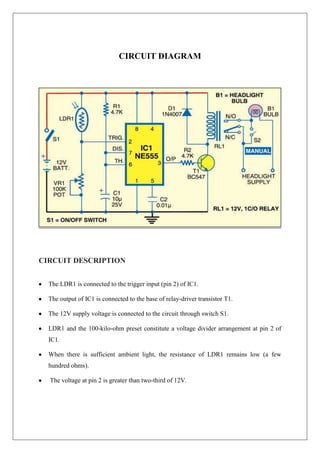


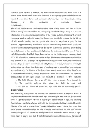
This document is a lab project report submitted by three students on an automatic headlight dimmer circuit. It includes an introduction describing the need for automatic headlight dimmers in vehicles. It then describes the circuit components used, including an NE555 timer IC, resistors, capacitors, an LDR light sensor, diode, potentiometer, relay and battery. The components are described in detail. The circuit diagram and working are also explained, indicating how the LDR sensor detects ambient light levels and the timer IC controls the relay to switch the headlights on and off automatically. Applications of the circuit and conclusions from the project are also mentioned.


