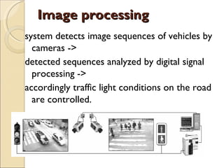
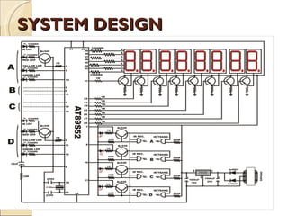
Group No. - 4

      SMART TRAFFIC LIGHT
         CONTROLLER


BY:
      Himanshi Sharma
Table of contents

 INTRODUCTION
 PURPOSE
 ENHANCEMENT
 SYSTEM OVERVIEW
 DESIGN OF PROJECT
 CONCLUSION
INTRODUCTION
 Traffic lights have become an integral part
  of human’s day-to-day life.
 With this motivation in the mind, this
  project aims at designing and
  implementing, a running model of traffic
  light controller which is controlled
  according to the density of vehicle on road.
 We will use AT89s52 microcontroller and
  Infra red sensor for performing all the
  computation and control related task
PURPOSE
 Control up to 4-phases traffic system with
  the traffic flow optimization strategies
 Optimize the traffic flow at network
  junctions
 Measurably improve traffic flow
 Reduce environmental pollution caused by
  traffic
 Most importantly increases road safety
ENHANCEMENT

•Bright   and energy-efficient – street lighting

•Image    processing

•Solar   panel
Bright and energy-efficient –
           street lighting
   The challenge
    ◦ Limited public funds
    ◦ Strict regulations
    ◦ Environmental protection
   The solution
    ◦ Contribute to public safety and security on
      streets and sidewalks
    ◦ Reduce the risk of accidents on roadways, cycle
      paths and sidewalks
    ◦ Makes a city more attractive, improves the
      quality of life
ARCHITECTURE OF STREET
LIGHT
SOLAR PANEL
•Life cycle costs typically 20% of
existing technology
•6 Watt to 45W Luminaries
•Battery selection with 10yr
guarantee
•Installation is easy
 Install the anti-skid, unloaded
the lamp pole, and install the
bracket on the solar panel, adjust
the solar panel's direction and
angle, then tight the screw at
last.
Benefits of Solar Panel
Image processing
system detects image sequences of vehicles by
  cameras ->
detected sequences analyzed by digital signal
  processing ->
accordingly traffic light conditions on the road
  are controlled.
Methodology ...
 Following are the steps involved
 F Image acquisition
 I RGB to gray conversion
 R Image enhancement
 I Image matching using edge detection
Different gamma levels..


           Gamma = 0.2


             Gamma = 4
EDGE DETECTED IMAGE:
   Edge detection of these real time images
    of the road is done with the help of
    prewitt edge detection operator
%age of matching..

0 to 10% - green light is on for 90 seconds.
10 to50% - green light is on for 60 seconds.
50 to 70% - green light is on for 30seconds.
70 to 90% - green light is on for 20 seconds
90 to 100% - red light is on for 60 seconds.
Continue…

                  Benefits:
 Reduction of vehicle-pedestrian conflicts
 Waiting time can be reduced or increased
 Duration of green light can be adapted to the
  users’ needs.
SYSTEM OVERVIEW
A pole traffic light is green
Other three poles are red
They are transmitting IR
wave from the IR
transmitting led
IR automated vehicle
ignition off circuit works
nearby 3-5 inch area
straight
It off the ignition supply of
the vehicle for stop
SYSTEM DESIGN
CONCLUSION
 Use of microcontroller instead of other
  controllers such as PLC makes the smart
  traffic controller hardware a low cost system
 The program downloaded into the
  microcontroller enables it to have a high
  accuracy timing, high independency and
  consistently
 It enables the proposed smart traffic
  controller system to realize traffic flow
  optimization strategies at a single or network
  junctions
Smart Traffic Light Controller

Smart Traffic Light Controller

  • 1.
    Group No. -4 SMART TRAFFIC LIGHT CONTROLLER BY: Himanshi Sharma
  • 2.
    Table of contents INTRODUCTION  PURPOSE  ENHANCEMENT  SYSTEM OVERVIEW  DESIGN OF PROJECT  CONCLUSION
  • 3.
    INTRODUCTION  Traffic lightshave become an integral part of human’s day-to-day life.  With this motivation in the mind, this project aims at designing and implementing, a running model of traffic light controller which is controlled according to the density of vehicle on road.  We will use AT89s52 microcontroller and Infra red sensor for performing all the computation and control related task
  • 4.
    PURPOSE  Control upto 4-phases traffic system with the traffic flow optimization strategies  Optimize the traffic flow at network junctions  Measurably improve traffic flow  Reduce environmental pollution caused by traffic  Most importantly increases road safety
  • 5.
    ENHANCEMENT •Bright and energy-efficient – street lighting •Image processing •Solar panel
  • 6.
    Bright and energy-efficient– street lighting  The challenge ◦ Limited public funds ◦ Strict regulations ◦ Environmental protection  The solution ◦ Contribute to public safety and security on streets and sidewalks ◦ Reduce the risk of accidents on roadways, cycle paths and sidewalks ◦ Makes a city more attractive, improves the quality of life
  • 7.
  • 8.
    SOLAR PANEL •Life cyclecosts typically 20% of existing technology •6 Watt to 45W Luminaries •Battery selection with 10yr guarantee •Installation is easy Install the anti-skid, unloaded the lamp pole, and install the bracket on the solar panel, adjust the solar panel's direction and angle, then tight the screw at last.
  • 9.
  • 10.
    Image processing system detectsimage sequences of vehicles by cameras -> detected sequences analyzed by digital signal processing -> accordingly traffic light conditions on the road are controlled.
  • 11.
    Methodology ...  Followingare the steps involved  F Image acquisition  I RGB to gray conversion  R Image enhancement  I Image matching using edge detection
  • 12.
    Different gamma levels.. Gamma = 0.2 Gamma = 4
  • 13.
    EDGE DETECTED IMAGE:  Edge detection of these real time images of the road is done with the help of prewitt edge detection operator
  • 14.
    %age of matching.. 0to 10% - green light is on for 90 seconds. 10 to50% - green light is on for 60 seconds. 50 to 70% - green light is on for 30seconds. 70 to 90% - green light is on for 20 seconds 90 to 100% - red light is on for 60 seconds.
  • 15.
    Continue… Benefits:  Reduction of vehicle-pedestrian conflicts  Waiting time can be reduced or increased  Duration of green light can be adapted to the users’ needs.
  • 16.
    SYSTEM OVERVIEW A poletraffic light is green Other three poles are red They are transmitting IR wave from the IR transmitting led IR automated vehicle ignition off circuit works nearby 3-5 inch area straight It off the ignition supply of the vehicle for stop
  • 17.
  • 18.
    CONCLUSION  Use ofmicrocontroller instead of other controllers such as PLC makes the smart traffic controller hardware a low cost system  The program downloaded into the microcontroller enables it to have a high accuracy timing, high independency and consistently  It enables the proposed smart traffic controller system to realize traffic flow optimization strategies at a single or network junctions