Download to read offline
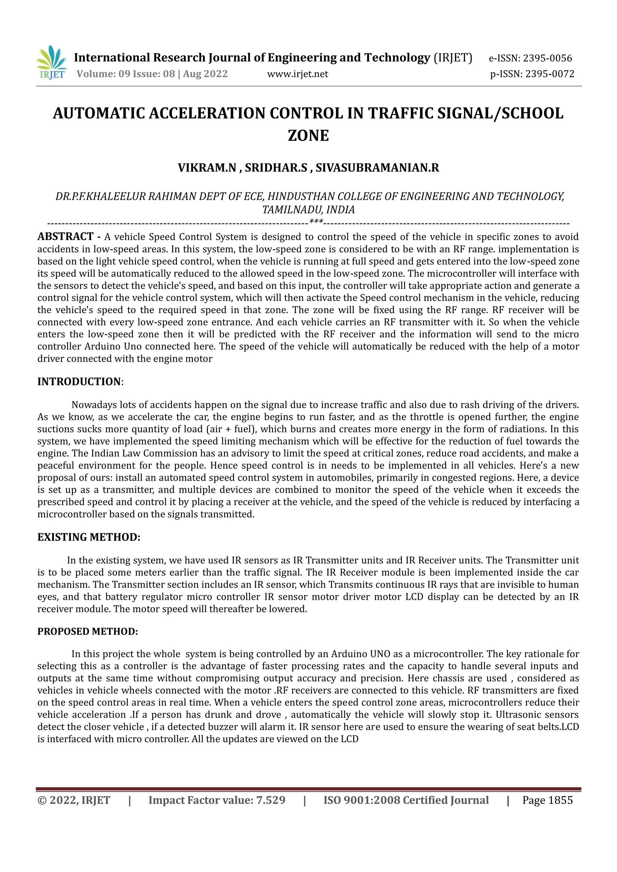
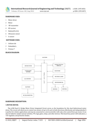
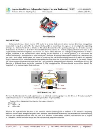
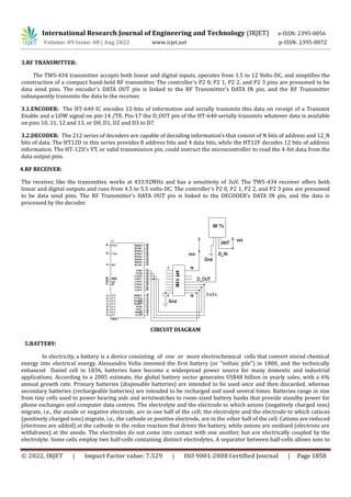
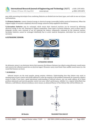
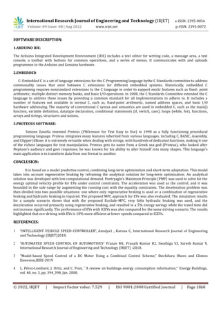

This document describes a proposed automatic vehicle acceleration control system for traffic signals and school zones. The system uses RF transmitters placed at the entrances to low-speed zones and RF receivers in vehicles. When a vehicle enters a low-speed zone, its microcontroller will reduce acceleration to limit the vehicle's speed. The system is intended to reduce accidents by enforcing speed limits at traffic signals and in school zones. It provides details on the hardware and software used, including RF modules, ultrasonic sensors, an Arduino microcontroller, and Proteus simulation software. The system is aimed at automatically controlling vehicle speed in specific zones to improve safety.