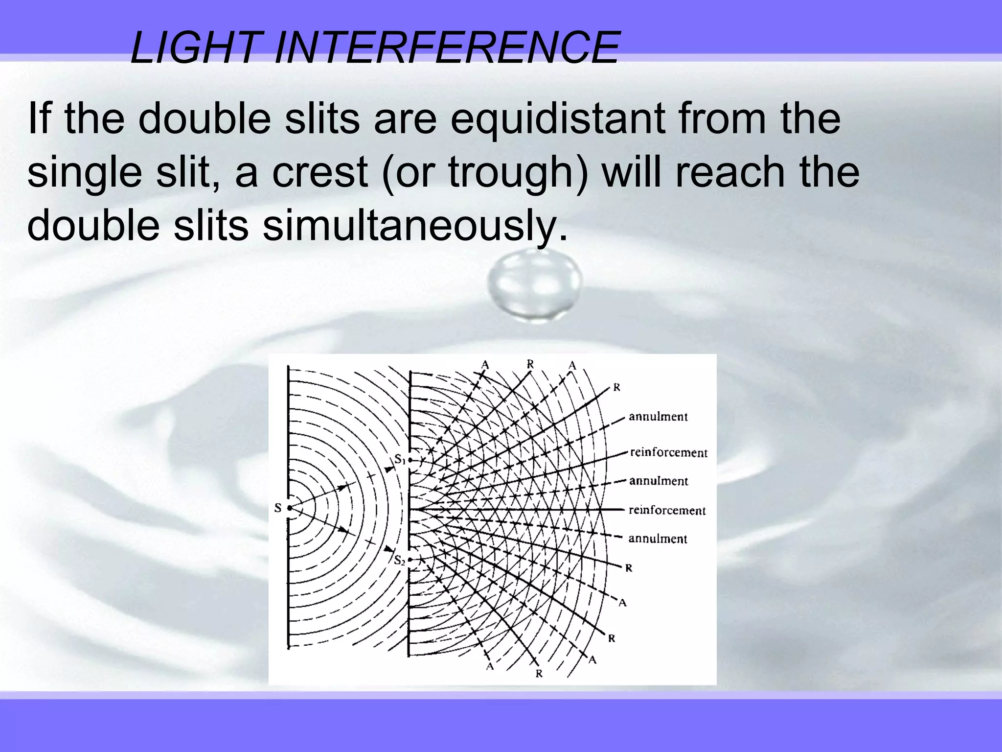
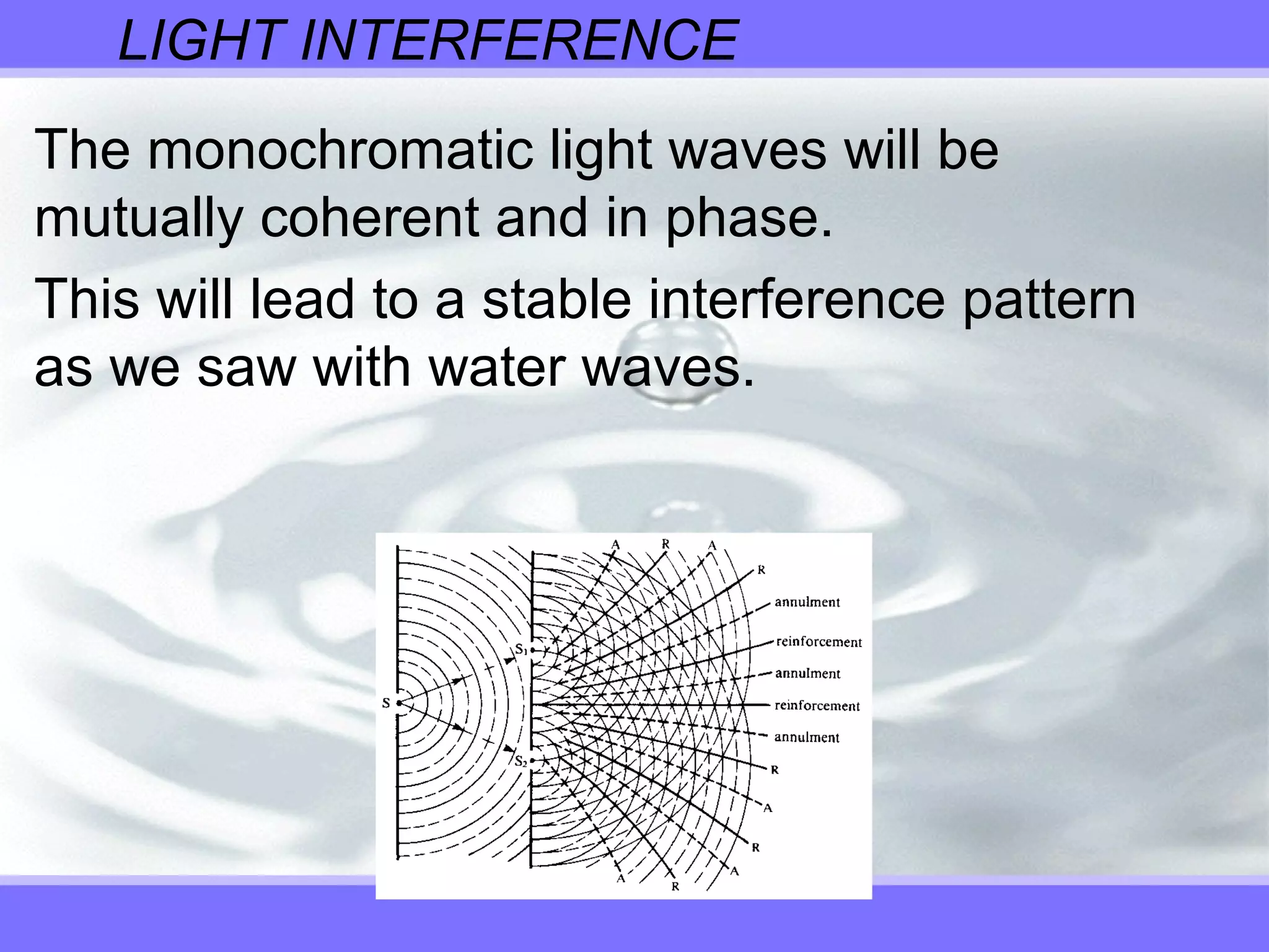
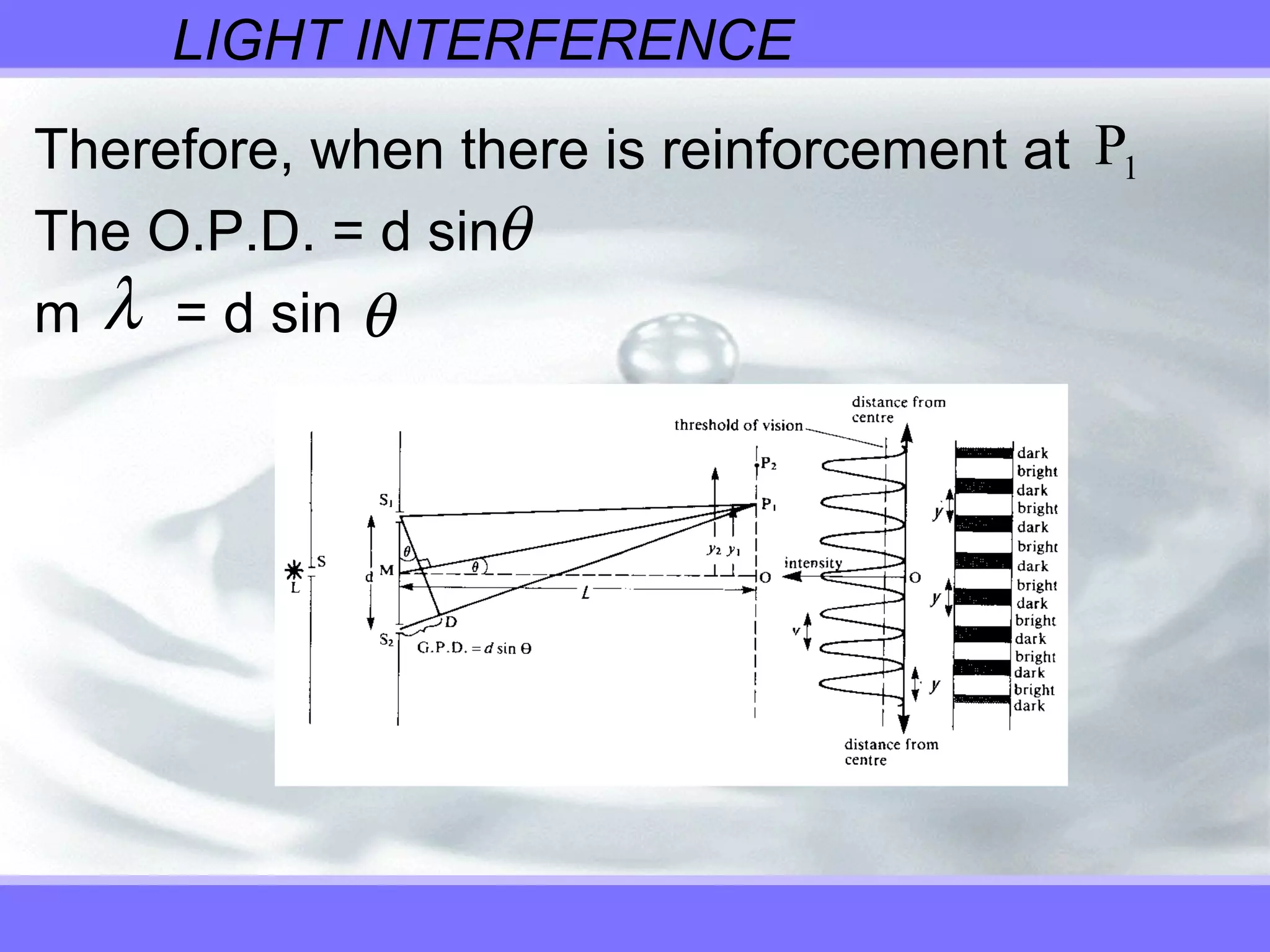
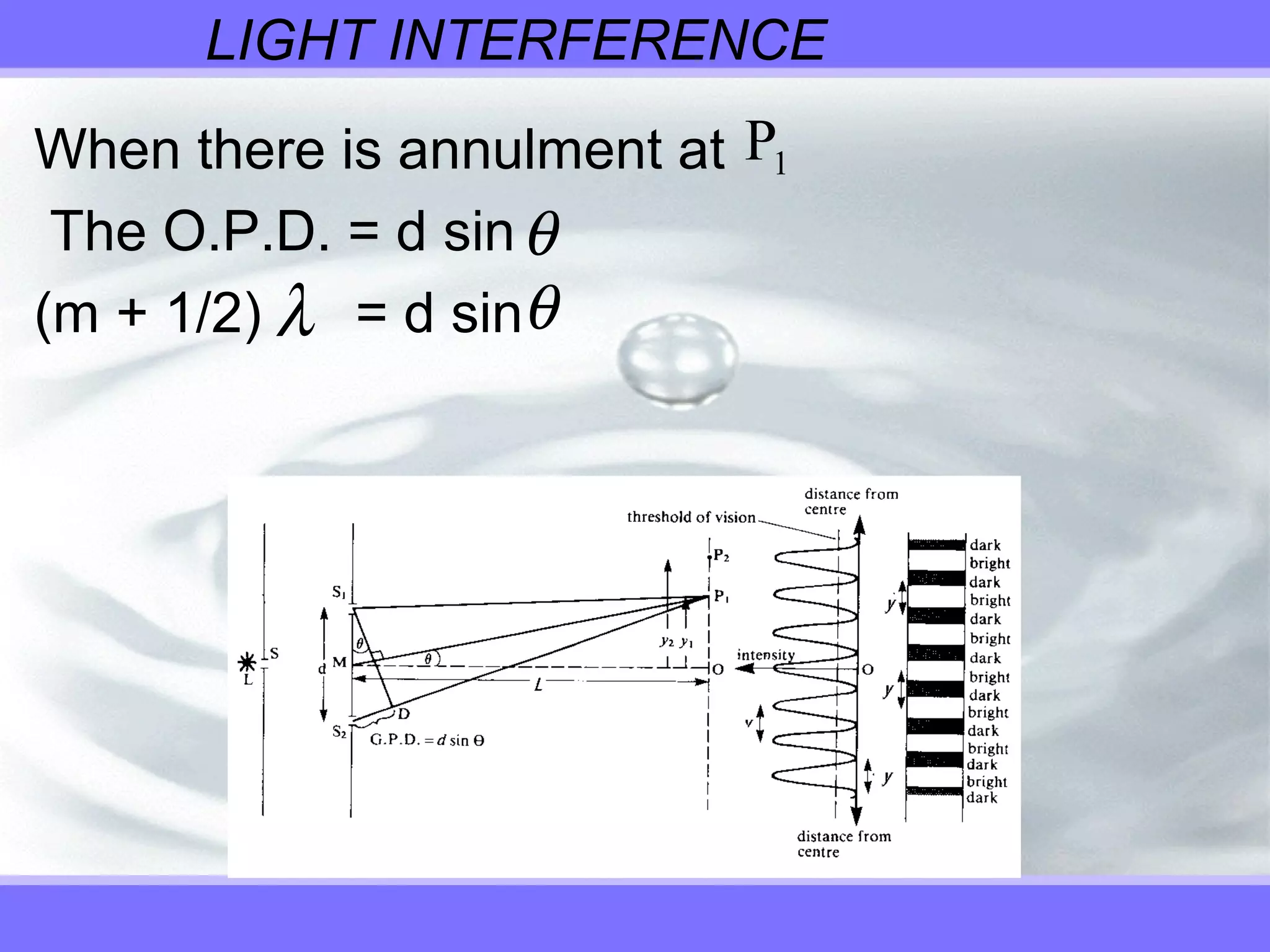
Waves
Topic 9.3 interference
INTERFERENCE
INTERFERENCE - occurs when two or
more waves pass through the same
space. CONSTRUCTIVE
INTERFERENCE - two waves that have
the same phase relationship and
frequency.
Example: Two waves that have
overlapping crests leads to a doubling of
the amplitude of the wave.
Constructive Wave Interference
INTERFERENCE
DESTRUCTIVE INTERFERENCE - two
waves are out of step.
Example: One waves crest meets another
waves trough. The waves will cancel each
other out.
Destructive Interference Explanation
Wave Interference Example 1
Wave Interference Example 2
INTERFERENCE
A constant phase relationship is maintained in
both constructive and destructive interference
when the frequency of both waves is the same.
We therefore say that the two sources that
produced the waves are mutually coherent.
INTERFERENCE
Mutual Coherence - two waves that are…
– Always constructive (in phase)
– Always destructive (one half wave out of phase)
– At the same points.
– Maintain a constant phase relationship.
LIGHT INTERFERENCE
In the case of light, it is the overlapping
electromagnetic waves that produce the
interference patterns.
It is difficult to observe interference patterns
with light due its very small wavelength of
around 4.7 x 10⁻⁷
m
The bandwidth would be extremely small (anti
nodes close together).
LIGHT INTERFERENCE
Also, any interference pattern produced by an
incandescent light bulb would not be sent out
in a synchronized fashion.
It would not be a monochromatic light source
due to the fact that there would be many
different frequencies.
It would also not be coherent (same phase
relationship) due to the fact that electrons...
LIGHT INTERFERENCE
… give off light at different times within the
atoms. This would mean that various crests
and troughs would not be synchronized even if
they were all of the same frequency.
The antinodal and nodal lines would be
constantly shifting.
LIGHT INTERFERENCE
A mutually coherent light source is necessary
to see an interference pattern.
Thomas Young (1800’s) devised a method of
doing this.
This is called the Young’s Double Slit
Experiment.
LIGHT INTERFERENCE
A single slit is illuminated with monochromatic
(light of all the same frequency) light. It might
be all blue light or all red light.
This slit becomes a point source and emits
circular wavefronts.
The light emerging from the slit is coherent
(only one crest or trough can get through at
any given time).
LIGHT INTERFERENCE
If the double slits are equidistant from the
single slit, a crest (or trough) will reach the
double slits simultaneously.
LIGHT INTERFERENCE
The monochromatic light waves will be
mutually coherent and in phase.
This will lead to a stable interference pattern
as we saw with water waves.
LIGHT INTERFERENCE
A sodium vapour lamp would be a good
monochromatic light source if using the
Young’s Slits Experiment.
If you are using a LASER there is no need for
the single slit as LASER light is already
monochromatic and coherent.
LIGHT INTERFERENCE
What would you see from all of this?
If you were to shine the double slit towards a
white screen you would see alternating bands
of bright and dark fringes on the screen.
The bright bands would be antinodal lines,
places where two crests (or troughs) were
overlapping.
LIGHT INTERFERENCE
The regions of darkness would be
nodal lines, places where a crest
and a trough were overlapping
and causing cancellation.
Young's Double
Slit Experiment
LIGHT INTERFERENCE
THE DERIVATION OF d sinθ = mλ
– This is an essential derivation from the syllabus.
– d = distance between the two slits.
– L = distance between the slits and the screen.
– y = the bandwidth (distance between
consecutive antinodes or consecutive nodes).
– Optical Path Difference (O.P.D.) = the extra
difference that one of the slits is from the screen.
LIGHT INTERFERENCE
LIGHT INTERFERENCE
bisects the angle by the two waves
that meet at . is at right angles to
in order that we have which is the extra
distance or the O.P.D. between the waves.
MP1
S PS1 2
P1
MP1
S D2
LIGHT INTERFERENCE
Since is very small, the angle is
approximately . This means that triangle
can be treated as a right angled
triangle
sin = or = d sin
Remember that is the Optical Path
Difference
θ S DS1 2
90o
S S D1 2
θ S D d2
S D2
θS D2
LIGHT INTERFERENCE
Therefore, when there is reinforcement at
The O.P.D. = d sin
m = d sin
P1
θ
λ θ
LIGHT INTERFERENCE
When there is annulment at
The O.P.D. = d sin
(m + 1/2) = d sin
P1
θ
λ θ
EVIDENCE FOR THE WAVE THEORY
Young’s experiment was important as at the
time, light was thought to be particle in nature
due to the influence of Sir Isaac Newton.
This result cannot be explained in terms of
particles but only in terms of waves.
EVIDENCE FOR THE WAVE THEORY
If it was particles, only one beam of particles
would pass through the first slit and be blocked
by the two slits as they are not in line.
Even if they did pass through, it would be
expected that 2 bright spots would be seen on
the screen.
DOUBLE SLIT DIFFRACTION
The pattern produced from monochromatic
light also has distinctive characteristics.
Each slit produces a diffraction pattern and
because the slits are so close, they coincide
on the screen.
From Young’s double slit, the bandwidth is
given by where d is the distance
between the centres of the slits.
∆y
L
d
=
λ
DOUBLE SLIT DIFFRACTION
The bandwidth for the diffraction fringes is
, where D is the width of each slit.
This is the same as the bandwidth for a single
slit diffraction pattern, and the central
diffraction band is twice the width of the side
bands.
∆y
L
D
=
λ
DOUBLE SLIT DIFFRACTION
Since D is much smaller than d, the diffraction
bands are larger than those in the interference
pattern. The result is an interference pattern
with fringes missing at regular intervals.
d
D
DOUBLE SLIT DIFFRACTION
Revisiting the single slit in Young’s experiment,
we would expect to get a diffraction pattern
from the single slit.
Over this you would also get an interference
pattern from the two slits.
DOUBLE SLIT DIFFRACTION
i n t e n s i t y
L
S
S1
S2
i n t e n s i t y
s c r e e n
i n t e r f e r e n c e
d i f f r a c t i o n
( d a s h e d e n v e l o p e )
d i s t a n c e f r o m c e n t r e
DOUBLE SLIT DIFFRACTION
We get not only an interference pattern but
also a diffraction pattern.
This is why we see a gradual dimming of light
intensity as we move away from the central
order antinode when we shine a LASER on a
wall.
DOUBLE SLIT DIFFRACTION
Using width of the slits = 10-4
m
Distance from single to double slits =10-1
m
Light of wavelength = 5 x 10⁻⁷
m
The bandwidth becomes:
∆y
L
D
=
λ
∆y =
5 x 10 x 10
10
-7 -1
-4
∆y = 5 x 10 m-4
DOUBLE SLIT DIFFRACTION
Thus the central band (2y) is 1.0 x 10⁻³
m.
The double slits are separated by a distance of
3 x 10⁻⁴
m, which is well within the intense
bright diffraction band produced by the single
slit.
Using a much narrower or broader band single
slit may reduce the intensity of the light
reaching the double slit.
MULTIPLE SLIT DIFFRACTION
The characteristics of multiple slits can be
summarised as below:
Interference fringes are superimposed on the
single slit diffraction pattern only when there
are least two slits enabling the interference of
waves to occur.
MULTIPLE SLIT DIFFRACTION
As the number of slits increases, the diffraction
pattern spreads and the intensity of each
reinforcement diminishes.
As the number of slits increases, each fringe
becomes narrower. This results in sharper
reinforcement bands.
MULTIPLE SLIT DIFFRACTION
The central bandwidth is no longer twice that
of fringe bands. The bandwidth equation can
no longer be used.
When there are a large number of slits, very
sharp reinforcement lines occur with non-
uniform spacing between them.
THE DIFFRACTION GRATING
A large number of equally spaced parallel slits which
can also be called an ‘interference grating’. There are
two types:
TRANSMISSION: Large number of equally
spaced scratches (6000 per cm is common) are
inscribed mechanically into a transparent material
such as glass. Each scratch becomes an opaque line
and the space in between becomes a slit.
THE DIFFRACTION GRATING
REFLECTION: Regularly spaced grooves in
a medium such as metallic or glass surface.
You can see the diffraction pattern on the
surface of a CD or DVD.
THE DIFFRACTION GRATING
Coherent light is directed on the diffraction
grating by passing light through a collimator
(light gatherer). The pattern can be seen
through the telescope. The whole arrangement
is called a spectrometer.
THE DIFFRACTION GRATING
The pattern is similar to Young’s double slit
pattern. The slits are narrow enough so that
diffraction by each of them spreads light over a
very wide angle on to a screen. Interference
occurs with light waves from all slits.
THE DIFFRACTION GRATING
We use the Spectroscope to find the
wavelengths of the different colours.
For reinforcement
Each wavelength of light (or different
colour) will have a unique angle that it is
diffracted to on the screen.
Diffraction Grating - Monochromatic Light
d m msin ( , , ,...)θ λ= = 0 1 2
THE DIFFRACTION GRATING
When m = 0, the central reinforcement line is
produced and is called the zero order
maximum.
First order maxima occur when m = 1 and
second order maxima when m = 2.
The diffraction pattern for a grating is different
to that from a double slit pattern.
The bright maxima are much narrower and
brighter for a grating.
THE DIFFRACTION GRATING
For a grating, the waves from two adjacent
slits will not be significantly out of phase but
those from a slit maybe 500 away, may be
exactly out of phase. Nearly all the light will
cancel out in pairs this way. The more lines,
the sharper the peaks will be.
Double Slit Multiple Slits
PRODUCING SPECTRUMS
This is a much more accurate way of
measuring the wavelength of light than using
two slits.
PRODUCING SPECTRUMS FROM WHITE
LIGHT USING A SPECTROSCOPE.
If the light is not monochromatic, the angles at
which the wavelengths produce their mth
order
maxima are different.
PRODUCING SPECTRUMS
If what light strikes a grating:
The central maximum (m=0) will be a sharp
white light since d sinθ = 0 for all wavelengths
at the zero order maxima
PRODUCING SPECTRUMS
On either side after the central white maxima
and an area of darkness, violet reinforces first
as it has the smallest wavelength, then the
other colours through to red.
A clear first order (m = 1) continuous spectrum
can be seen.
PRODUCING SPECTRUMS
Higher order spectra
become spread further
and become less intense.
The pattern will overlap
from the third order
onwards and the
bandwidth formula used in
the double slit cannot be
used.
PRODUCING SPECTRUMS
A small wavelength equals a small sin
Blue light makes a small angle.
θ
sinθ
λ
=
m
d
EXAMPLE 3
Light from a sodium vapour lamp (m) falls on a
grating with 5000 lines per centimetre. Find the
angular positions of all the reinforcement
positions observed. The wavelength of Sodium
vapour (orange light) is 5.98 x 10⁻⁷
metres.
EXAMPLE 3 SOLUTION
EXAMPLE 3 SOLUTION
Thin film interference
Have you seen:
•streaks of colour on a car windshield shortly
after it has been swiped by a windshield wiper
•streaks of colour in a puddle or soap bubble.
These are the result of interference of light by
the very thin film of water/soap/oil that remains
on the windshield.
This is called thin film interference.
Image from hyperphysics
Thin film interference results from the thickness of
the layer. It is important to remember that a 180
degree phase change occurs when a wave reflects
from a surface, but no phase change for the
reflection from the internal surface. The colour seen
depends also upon the viewing angle.
Anti-reflection coatings (hyperphysics)

9.3 interference

  • 1.
  • 2.
    INTERFERENCE INTERFERENCE - occurswhen two or more waves pass through the same space. CONSTRUCTIVE INTERFERENCE - two waves that have the same phase relationship and frequency. Example: Two waves that have overlapping crests leads to a doubling of the amplitude of the wave. Constructive Wave Interference
  • 3.
    INTERFERENCE DESTRUCTIVE INTERFERENCE -two waves are out of step. Example: One waves crest meets another waves trough. The waves will cancel each other out. Destructive Interference Explanation Wave Interference Example 1 Wave Interference Example 2
  • 4.
    INTERFERENCE A constant phaserelationship is maintained in both constructive and destructive interference when the frequency of both waves is the same. We therefore say that the two sources that produced the waves are mutually coherent.
  • 5.
    INTERFERENCE Mutual Coherence -two waves that are… – Always constructive (in phase) – Always destructive (one half wave out of phase) – At the same points. – Maintain a constant phase relationship.
  • 6.
    LIGHT INTERFERENCE In thecase of light, it is the overlapping electromagnetic waves that produce the interference patterns. It is difficult to observe interference patterns with light due its very small wavelength of around 4.7 x 10⁻⁷ m The bandwidth would be extremely small (anti nodes close together).
  • 7.
    LIGHT INTERFERENCE Also, anyinterference pattern produced by an incandescent light bulb would not be sent out in a synchronized fashion. It would not be a monochromatic light source due to the fact that there would be many different frequencies. It would also not be coherent (same phase relationship) due to the fact that electrons...
  • 8.
    LIGHT INTERFERENCE … giveoff light at different times within the atoms. This would mean that various crests and troughs would not be synchronized even if they were all of the same frequency. The antinodal and nodal lines would be constantly shifting.
  • 9.
    LIGHT INTERFERENCE A mutuallycoherent light source is necessary to see an interference pattern. Thomas Young (1800’s) devised a method of doing this. This is called the Young’s Double Slit Experiment.
  • 10.
    LIGHT INTERFERENCE A singleslit is illuminated with monochromatic (light of all the same frequency) light. It might be all blue light or all red light. This slit becomes a point source and emits circular wavefronts. The light emerging from the slit is coherent (only one crest or trough can get through at any given time).
  • 11.
    LIGHT INTERFERENCE If thedouble slits are equidistant from the single slit, a crest (or trough) will reach the double slits simultaneously.
  • 12.
    LIGHT INTERFERENCE The monochromaticlight waves will be mutually coherent and in phase. This will lead to a stable interference pattern as we saw with water waves.
  • 13.
    LIGHT INTERFERENCE A sodiumvapour lamp would be a good monochromatic light source if using the Young’s Slits Experiment. If you are using a LASER there is no need for the single slit as LASER light is already monochromatic and coherent.
  • 14.
    LIGHT INTERFERENCE What wouldyou see from all of this? If you were to shine the double slit towards a white screen you would see alternating bands of bright and dark fringes on the screen. The bright bands would be antinodal lines, places where two crests (or troughs) were overlapping.
  • 15.
    LIGHT INTERFERENCE The regionsof darkness would be nodal lines, places where a crest and a trough were overlapping and causing cancellation. Young's Double Slit Experiment
  • 16.
    LIGHT INTERFERENCE THE DERIVATIONOF d sinθ = mλ – This is an essential derivation from the syllabus. – d = distance between the two slits. – L = distance between the slits and the screen. – y = the bandwidth (distance between consecutive antinodes or consecutive nodes). – Optical Path Difference (O.P.D.) = the extra difference that one of the slits is from the screen.
  • 17.
  • 18.
    LIGHT INTERFERENCE bisects theangle by the two waves that meet at . is at right angles to in order that we have which is the extra distance or the O.P.D. between the waves. MP1 S PS1 2 P1 MP1 S D2
  • 19.
    LIGHT INTERFERENCE Since isvery small, the angle is approximately . This means that triangle can be treated as a right angled triangle sin = or = d sin Remember that is the Optical Path Difference θ S DS1 2 90o S S D1 2 θ S D d2 S D2 θS D2
  • 20.
    LIGHT INTERFERENCE Therefore, whenthere is reinforcement at The O.P.D. = d sin m = d sin P1 θ λ θ
  • 21.
    LIGHT INTERFERENCE When thereis annulment at The O.P.D. = d sin (m + 1/2) = d sin P1 θ λ θ
  • 22.
    EVIDENCE FOR THEWAVE THEORY Young’s experiment was important as at the time, light was thought to be particle in nature due to the influence of Sir Isaac Newton. This result cannot be explained in terms of particles but only in terms of waves.
  • 23.
    EVIDENCE FOR THEWAVE THEORY If it was particles, only one beam of particles would pass through the first slit and be blocked by the two slits as they are not in line. Even if they did pass through, it would be expected that 2 bright spots would be seen on the screen.
  • 24.
    DOUBLE SLIT DIFFRACTION Thepattern produced from monochromatic light also has distinctive characteristics. Each slit produces a diffraction pattern and because the slits are so close, they coincide on the screen. From Young’s double slit, the bandwidth is given by where d is the distance between the centres of the slits. ∆y L d = λ
  • 25.
    DOUBLE SLIT DIFFRACTION Thebandwidth for the diffraction fringes is , where D is the width of each slit. This is the same as the bandwidth for a single slit diffraction pattern, and the central diffraction band is twice the width of the side bands. ∆y L D = λ
  • 26.
    DOUBLE SLIT DIFFRACTION SinceD is much smaller than d, the diffraction bands are larger than those in the interference pattern. The result is an interference pattern with fringes missing at regular intervals. d D
  • 27.
    DOUBLE SLIT DIFFRACTION Revisitingthe single slit in Young’s experiment, we would expect to get a diffraction pattern from the single slit. Over this you would also get an interference pattern from the two slits.
  • 28.
    DOUBLE SLIT DIFFRACTION in t e n s i t y L S S1 S2 i n t e n s i t y s c r e e n i n t e r f e r e n c e d i f f r a c t i o n ( d a s h e d e n v e l o p e ) d i s t a n c e f r o m c e n t r e
  • 29.
    DOUBLE SLIT DIFFRACTION Weget not only an interference pattern but also a diffraction pattern. This is why we see a gradual dimming of light intensity as we move away from the central order antinode when we shine a LASER on a wall.
  • 30.
    DOUBLE SLIT DIFFRACTION Usingwidth of the slits = 10-4 m Distance from single to double slits =10-1 m Light of wavelength = 5 x 10⁻⁷ m The bandwidth becomes: ∆y L D = λ ∆y = 5 x 10 x 10 10 -7 -1 -4 ∆y = 5 x 10 m-4
  • 31.
    DOUBLE SLIT DIFFRACTION Thusthe central band (2y) is 1.0 x 10⁻³ m. The double slits are separated by a distance of 3 x 10⁻⁴ m, which is well within the intense bright diffraction band produced by the single slit. Using a much narrower or broader band single slit may reduce the intensity of the light reaching the double slit.
  • 32.
    MULTIPLE SLIT DIFFRACTION Thecharacteristics of multiple slits can be summarised as below: Interference fringes are superimposed on the single slit diffraction pattern only when there are least two slits enabling the interference of waves to occur.
  • 33.
    MULTIPLE SLIT DIFFRACTION Asthe number of slits increases, the diffraction pattern spreads and the intensity of each reinforcement diminishes. As the number of slits increases, each fringe becomes narrower. This results in sharper reinforcement bands.
  • 34.
    MULTIPLE SLIT DIFFRACTION Thecentral bandwidth is no longer twice that of fringe bands. The bandwidth equation can no longer be used. When there are a large number of slits, very sharp reinforcement lines occur with non- uniform spacing between them.
  • 35.
    THE DIFFRACTION GRATING Alarge number of equally spaced parallel slits which can also be called an ‘interference grating’. There are two types: TRANSMISSION: Large number of equally spaced scratches (6000 per cm is common) are inscribed mechanically into a transparent material such as glass. Each scratch becomes an opaque line and the space in between becomes a slit.
  • 36.
    THE DIFFRACTION GRATING REFLECTION:Regularly spaced grooves in a medium such as metallic or glass surface. You can see the diffraction pattern on the surface of a CD or DVD.
  • 37.
    THE DIFFRACTION GRATING Coherentlight is directed on the diffraction grating by passing light through a collimator (light gatherer). The pattern can be seen through the telescope. The whole arrangement is called a spectrometer.
  • 38.
    THE DIFFRACTION GRATING Thepattern is similar to Young’s double slit pattern. The slits are narrow enough so that diffraction by each of them spreads light over a very wide angle on to a screen. Interference occurs with light waves from all slits.
  • 39.
    THE DIFFRACTION GRATING Weuse the Spectroscope to find the wavelengths of the different colours. For reinforcement Each wavelength of light (or different colour) will have a unique angle that it is diffracted to on the screen. Diffraction Grating - Monochromatic Light d m msin ( , , ,...)θ λ= = 0 1 2
  • 40.
    THE DIFFRACTION GRATING Whenm = 0, the central reinforcement line is produced and is called the zero order maximum. First order maxima occur when m = 1 and second order maxima when m = 2. The diffraction pattern for a grating is different to that from a double slit pattern. The bright maxima are much narrower and brighter for a grating.
  • 41.
    THE DIFFRACTION GRATING Fora grating, the waves from two adjacent slits will not be significantly out of phase but those from a slit maybe 500 away, may be exactly out of phase. Nearly all the light will cancel out in pairs this way. The more lines, the sharper the peaks will be. Double Slit Multiple Slits
  • 42.
    PRODUCING SPECTRUMS This isa much more accurate way of measuring the wavelength of light than using two slits. PRODUCING SPECTRUMS FROM WHITE LIGHT USING A SPECTROSCOPE. If the light is not monochromatic, the angles at which the wavelengths produce their mth order maxima are different.
  • 43.
    PRODUCING SPECTRUMS If whatlight strikes a grating: The central maximum (m=0) will be a sharp white light since d sinθ = 0 for all wavelengths at the zero order maxima
  • 44.
    PRODUCING SPECTRUMS On eitherside after the central white maxima and an area of darkness, violet reinforces first as it has the smallest wavelength, then the other colours through to red. A clear first order (m = 1) continuous spectrum can be seen.
  • 45.
    PRODUCING SPECTRUMS Higher orderspectra become spread further and become less intense. The pattern will overlap from the third order onwards and the bandwidth formula used in the double slit cannot be used.
  • 46.
    PRODUCING SPECTRUMS A smallwavelength equals a small sin Blue light makes a small angle. θ sinθ λ = m d
  • 47.
    EXAMPLE 3 Light froma sodium vapour lamp (m) falls on a grating with 5000 lines per centimetre. Find the angular positions of all the reinforcement positions observed. The wavelength of Sodium vapour (orange light) is 5.98 x 10⁻⁷ metres.
  • 48.
  • 49.
  • 50.
    Thin film interference Haveyou seen: •streaks of colour on a car windshield shortly after it has been swiped by a windshield wiper •streaks of colour in a puddle or soap bubble. These are the result of interference of light by the very thin film of water/soap/oil that remains on the windshield. This is called thin film interference.
  • 52.
    Image from hyperphysics Thinfilm interference results from the thickness of the layer. It is important to remember that a 180 degree phase change occurs when a wave reflects from a surface, but no phase change for the reflection from the internal surface. The colour seen depends also upon the viewing angle.
  • 53.