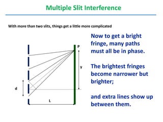
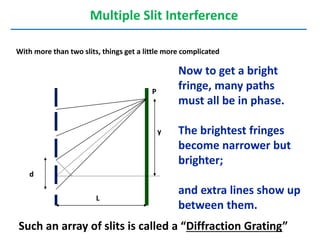
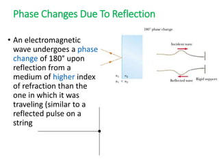
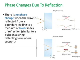
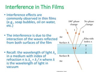
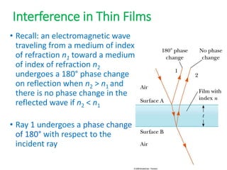
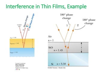
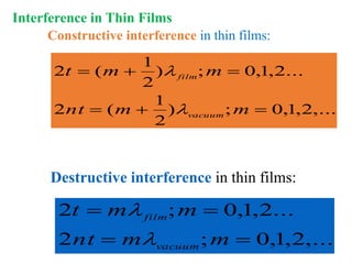
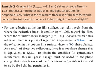
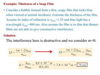
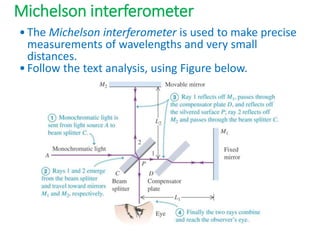
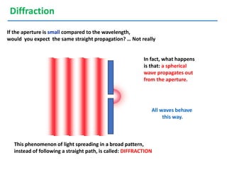
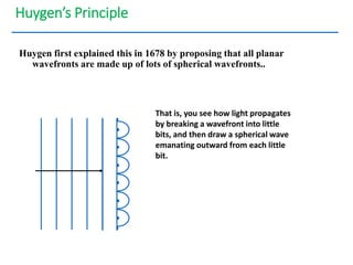
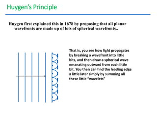
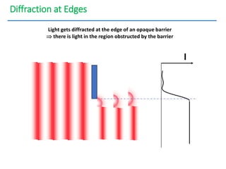
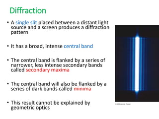
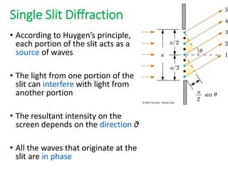
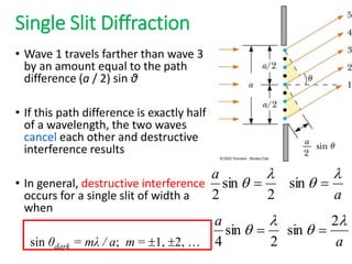
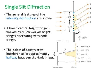
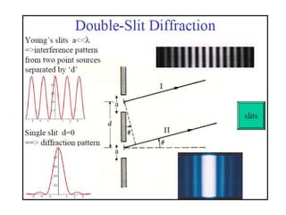
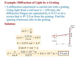
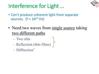
- The document discusses interference of light waves, specifically the interference patterns produced in Young's double slit experiment.
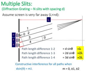
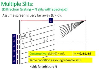
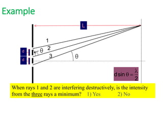
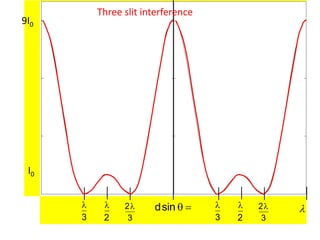
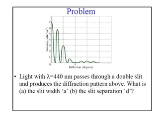
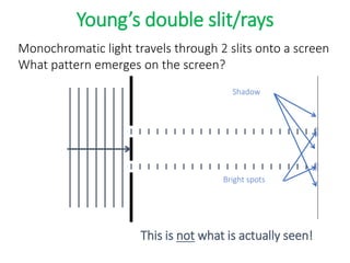
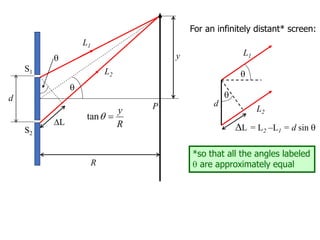
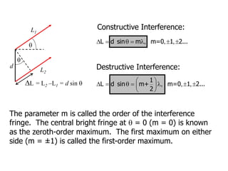
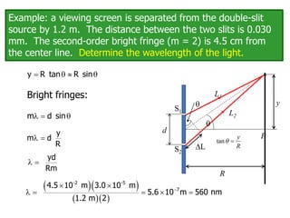
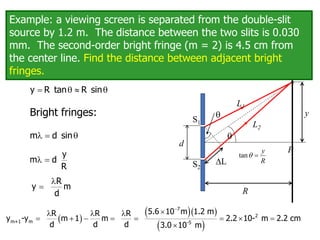
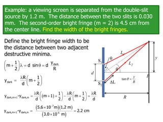
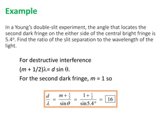
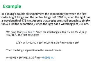
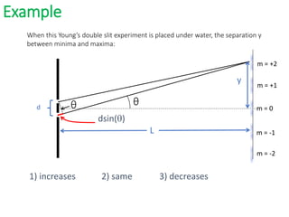
- In Young's double slit experiment, light passing through two slits will produce a pattern of bright and dark fringes on a screen due to the interference of the light waves. Where the path difference between waves is an integral number of wavelengths, constructive interference occurs, appearing as bright fringes.
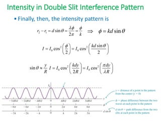
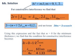
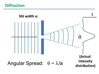
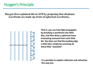
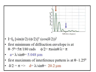
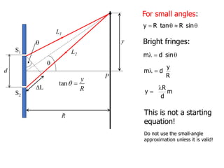
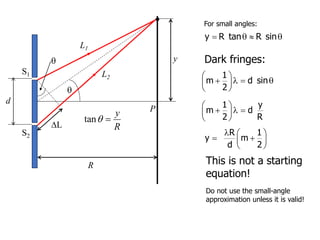
- The position of the bright and dark fringes can be calculated based on the path difference formula involving the slit separation distance, the angle between the waves, and the wavelength of light. This allows one to determine properties of the light from measurements of the interference pattern.


![R or L
d
y
r1
r2
q
P
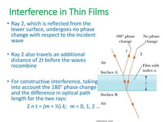
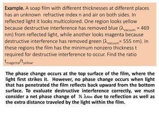
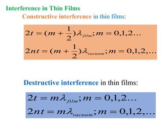
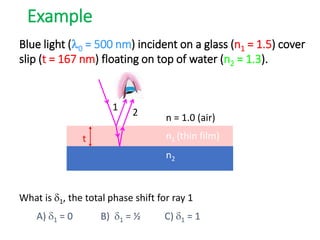
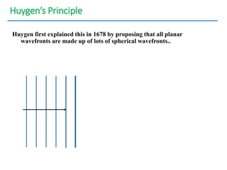
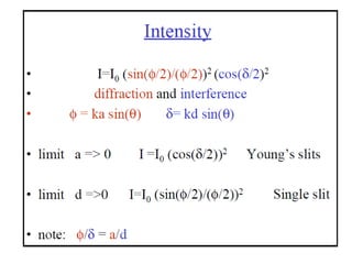
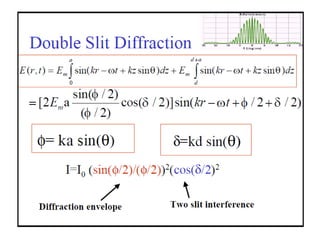
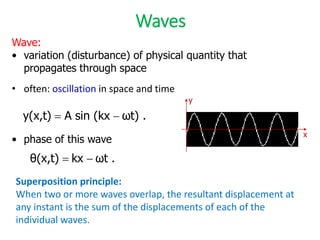
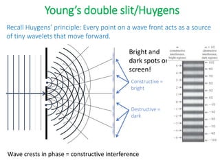
Intensity in Double Slit Interference Pattern
This expression can be transformed using:
sin + sin = 2 [sin ( + ) / 2] [cos ( - ) / 2]
with = t and = t +
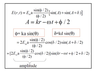
The electric field at P is E = E1 + E2
E = EP sin (t) + EP sin (t + )
E = EP [sin (t) + sin (t + )]
E = 2 Ep cos ( /2) sin (t + /2)](https://image.slidesharecdn.com/optics-240224033918-d3fdfea1/85/AN-INTRODUCTION-TO-ENGINEERRING-Optics-pptx-22-320.jpg)
![R or L
d
y
r1
r2
q
P
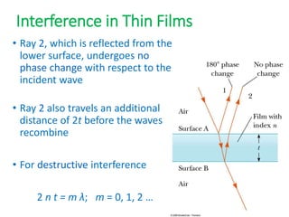
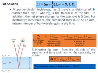
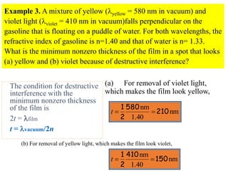
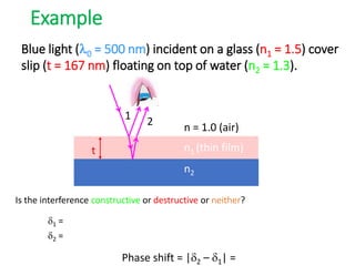
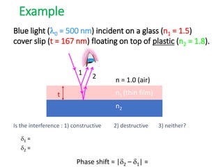
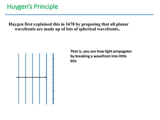
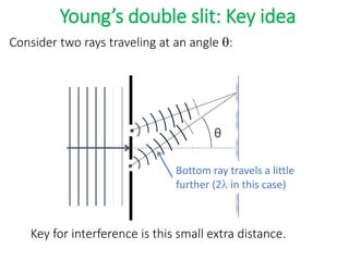
Intensity in Double Slit Interference Pattern
The electric field at P is E = E1 + E2
E = 2 Ep cos ( /2) sin (t + /2)
Path difference is d sin q / 2 = d sin q / 2
d sin q
E = 2 EP cos [ d sin q / ] sin (t + /2)](https://image.slidesharecdn.com/optics-240224033918-d3fdfea1/85/AN-INTRODUCTION-TO-ENGINEERRING-Optics-pptx-23-320.jpg)