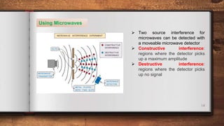
DIFRACTION &
INTERFERENCE
GRADE 11
AS / A LEVEL – PHYSICS – 9702
SpInS Interactional School
2
Diffraction
 Diffraction is the spreading out of
waves when they pass an obstruction
This obstruction is typically a narrow
slit (an aperture)
 The extent of diffraction depends on
the width of the gap compared with the
wavelength of the waves
Diffraction is the most prominent when
the width of the slit is approximately
equal to the wavelength
3
 Diffraction is usually represented by a
wavefront as shown by the vertical lines in
the diagram above
 The only property of a wave that changes
when its diffracted is its amplitude
This is because some energy is dissipated
when a wave is diffracted through a gap
 Diffraction can also occur when waves curve
around an edge:
4
Diffraction Experiments
 As discussed above, the effects of diffraction are most prominent when the gap
size is approximately the same or smaller than the wavelength of the wave
 As the gap size increases, the effect gradually gets less pronounced until, in the
case that the gap is much larger than the wavelength, the waves are no longer
spread out
5
6
Interference & Coherence
 Interference occurs when waves overlap and their resultant displacement is the
sum of the displacement of each wave
 This result is based on the principle of superposition and the resultant waves
may be smaller or larger than either of the two individual waves
 Interference of two waves can either be:
In phase, causing constructive interference. The peaks and troughs line
up on both waves. The resultant wave has double the amplitude
in anti-phase, causing destructive interference. The peaks on one wave
line up with the troughs of the other. The resultant wave has no amplitude
7
8
 At points where the two waves are neither in phase nor in antiphase, the resultant
amplitude is somewhere in between the two extremes
 Waves are coherent if they have the same frequency and constant phase difference
 Coherence is vital in order to produce an observable interference pattern
 Laser light is an example of a coherent light source, whereas filament lamps
produce incoherent light waves
9
10
11
Two Source Interference
Using Water Waves
 Two-source interference in can be demonstrated in water using ripple tanks
 The diagram below shows diffracted circle shaped water waves from two point
sources eg. dropping two pebbles near to each other in a pond
12
 The two waves interfere
causing areas of
constructive and
destructive interference
 The lines of maximum
displacement occur when
all the peaks and troughs
line up with those on
another wave
13
Using Sound Waves
 Sound waves are longitudinal
waves so are made up of
compressions and rarefactions
 Constructive interference
occurs when two compressions or
two rarefactions line up and the
sound appears louder
 Destructive interference occurs
when a compression lines up with
a rarefaction and vice versa. The
sound is quieter
This is the technology used in
noise-cancelling headphones
14
Using Microwaves
 Two source interference for
microwaves can be detected with
a moveable microwave detector
 Constructive interference:
regions where the detector picks
up a maximum amplitude
 Destructive interference:
regions where the detector picks
up no signal
15
Using Light Waves
 For light rays, such as a laser
light through two slits, an
interference pattern forms on
the screen
 Constructive interference is
shown as bright fringes on the
screen
The highest intensity is in
the
middle
 Destructive interference is
shown as the dark fringes on
the screen
These have zero intensity
16
Two Source Interference Fringes
 For two-source interference fringes to be observed, the sources of the wave
must be:
Coherent (constant phase difference)
Monochromatic (single wavelength)
 When two waves interfere, the resultant wave depends on the phase difference
between the two waves
 This is proportional to the path difference between the waves which can be
written in terms of the wavelength λ of the wave
 As seen from the diagram, the wave from slit S2 has to travel slightly further
than that from S1 to reach the same point on the screen. The difference in
distance is the path difference
17
18
 For constructive interference (or maxima), the difference in wavelengths will be
an integer number of whole wavelengths
 For destructive interference (or minima) it will be an integer number of whole
wavelengths plus a half wavelength
n is the order of the maxima/minima since there is usually more than one
of these produced by the interference pattern
19
20
21
Double slit Experiment
and Diffraction Grating
23
Young's Double Slit Experiment
 Young’s double slit experiment
demonstrates how light waves
produced an interference pattern
 When a monochromatic light
source is placed behind a single
slit, the light is diffracted
producing two light sources at the
double slits A and B
 Since both light sources originate
from the same primary source,
they are coherent and will
therefore create an observable
interference pattern
 Both diffracted light from the
double slits create an interference
pattern made up of bright and
dark fringes
24
The wavelength of the light can be calculated from the interference pattern and
experiment set up. These are related using the double-slit equation
25
 The interference pattern on a screen will show as ‘fringes’ which are dark or bright
bands
 Constructive interference is shown through bright fringes with varying intensity
(most intense in the middle)
 Destructive interference is shown from dark fringes where no light is seen
 A monochromatic light source makes these fringes clearer and the distance
between fringes is very small due to the short wavelength of visible light
26
27
28
The Diffraction
Grating
 A diffraction grating is a plate on which there is a very large number of parallel,
identical, close-spaced slits
 When monochromatic light is incident on a grating, a pattern of narrow bright
fringes is produced on a screen
29
The angles at which the maxima of intensity (constructive interference) are
produced can be deduced by the diffraction grating equation
30
Angular Separation
 The angular separation of each maxima is calculated by rearranging the grating
equation to make θ the subject
 The angle θ is taken from the centre meaning the higher orders are at greater
angles
31
 The angular separation between two angles is found by subtracting the smaller
angle from the larger one
 The angular separation between the first and second maxima n1 and n2 is θ2 –
θ1
 The maximum angle to see orders of maxima is when the beam is at right
angles to the diffraction grating. This means θ = 90o and sin(θ) = 1
32
33

G11 - Wave last.pptx

  • 1.
    DIFRACTION & INTERFERENCE GRADE 11 AS/ A LEVEL – PHYSICS – 9702 SpInS Interactional School
  • 2.
    2 Diffraction  Diffraction isthe spreading out of waves when they pass an obstruction This obstruction is typically a narrow slit (an aperture)  The extent of diffraction depends on the width of the gap compared with the wavelength of the waves Diffraction is the most prominent when the width of the slit is approximately equal to the wavelength
  • 3.
    3  Diffraction isusually represented by a wavefront as shown by the vertical lines in the diagram above  The only property of a wave that changes when its diffracted is its amplitude This is because some energy is dissipated when a wave is diffracted through a gap  Diffraction can also occur when waves curve around an edge:
  • 4.
    4 Diffraction Experiments  Asdiscussed above, the effects of diffraction are most prominent when the gap size is approximately the same or smaller than the wavelength of the wave  As the gap size increases, the effect gradually gets less pronounced until, in the case that the gap is much larger than the wavelength, the waves are no longer spread out
  • 5.
  • 6.
    6 Interference & Coherence Interference occurs when waves overlap and their resultant displacement is the sum of the displacement of each wave  This result is based on the principle of superposition and the resultant waves may be smaller or larger than either of the two individual waves  Interference of two waves can either be: In phase, causing constructive interference. The peaks and troughs line up on both waves. The resultant wave has double the amplitude in anti-phase, causing destructive interference. The peaks on one wave line up with the troughs of the other. The resultant wave has no amplitude
  • 7.
  • 8.
    8  At pointswhere the two waves are neither in phase nor in antiphase, the resultant amplitude is somewhere in between the two extremes  Waves are coherent if they have the same frequency and constant phase difference  Coherence is vital in order to produce an observable interference pattern  Laser light is an example of a coherent light source, whereas filament lamps produce incoherent light waves
  • 9.
  • 10.
  • 11.
    11 Two Source Interference UsingWater Waves  Two-source interference in can be demonstrated in water using ripple tanks  The diagram below shows diffracted circle shaped water waves from two point sources eg. dropping two pebbles near to each other in a pond
  • 12.
    12  The twowaves interfere causing areas of constructive and destructive interference  The lines of maximum displacement occur when all the peaks and troughs line up with those on another wave
  • 13.
    13 Using Sound Waves Sound waves are longitudinal waves so are made up of compressions and rarefactions  Constructive interference occurs when two compressions or two rarefactions line up and the sound appears louder  Destructive interference occurs when a compression lines up with a rarefaction and vice versa. The sound is quieter This is the technology used in noise-cancelling headphones
  • 14.
    14 Using Microwaves  Twosource interference for microwaves can be detected with a moveable microwave detector  Constructive interference: regions where the detector picks up a maximum amplitude  Destructive interference: regions where the detector picks up no signal
  • 15.
    15 Using Light Waves For light rays, such as a laser light through two slits, an interference pattern forms on the screen  Constructive interference is shown as bright fringes on the screen The highest intensity is in the middle  Destructive interference is shown as the dark fringes on the screen These have zero intensity
  • 16.
    16 Two Source InterferenceFringes  For two-source interference fringes to be observed, the sources of the wave must be: Coherent (constant phase difference) Monochromatic (single wavelength)  When two waves interfere, the resultant wave depends on the phase difference between the two waves  This is proportional to the path difference between the waves which can be written in terms of the wavelength λ of the wave  As seen from the diagram, the wave from slit S2 has to travel slightly further than that from S1 to reach the same point on the screen. The difference in distance is the path difference
  • 17.
  • 18.
    18  For constructiveinterference (or maxima), the difference in wavelengths will be an integer number of whole wavelengths  For destructive interference (or minima) it will be an integer number of whole wavelengths plus a half wavelength n is the order of the maxima/minima since there is usually more than one of these produced by the interference pattern
  • 19.
  • 20.
  • 21.
  • 22.
    Double slit Experiment andDiffraction Grating
  • 23.
    23 Young's Double SlitExperiment  Young’s double slit experiment demonstrates how light waves produced an interference pattern  When a monochromatic light source is placed behind a single slit, the light is diffracted producing two light sources at the double slits A and B  Since both light sources originate from the same primary source, they are coherent and will therefore create an observable interference pattern  Both diffracted light from the double slits create an interference pattern made up of bright and dark fringes
  • 24.
    24 The wavelength ofthe light can be calculated from the interference pattern and experiment set up. These are related using the double-slit equation
  • 25.
    25  The interferencepattern on a screen will show as ‘fringes’ which are dark or bright bands  Constructive interference is shown through bright fringes with varying intensity (most intense in the middle)  Destructive interference is shown from dark fringes where no light is seen  A monochromatic light source makes these fringes clearer and the distance between fringes is very small due to the short wavelength of visible light
  • 26.
  • 27.
  • 28.
    28 The Diffraction Grating  Adiffraction grating is a plate on which there is a very large number of parallel, identical, close-spaced slits  When monochromatic light is incident on a grating, a pattern of narrow bright fringes is produced on a screen
  • 29.
    29 The angles atwhich the maxima of intensity (constructive interference) are produced can be deduced by the diffraction grating equation
  • 30.
    30 Angular Separation  Theangular separation of each maxima is calculated by rearranging the grating equation to make θ the subject  The angle θ is taken from the centre meaning the higher orders are at greater angles
  • 31.
    31  The angularseparation between two angles is found by subtracting the smaller angle from the larger one  The angular separation between the first and second maxima n1 and n2 is θ2 – θ1  The maximum angle to see orders of maxima is when the beam is at right angles to the diffraction grating. This means θ = 90o and sin(θ) = 1
  • 32.
  • 33.