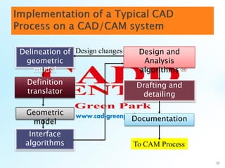
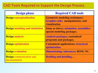
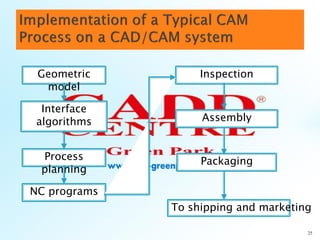
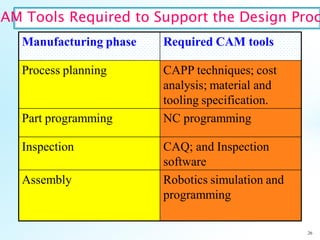
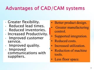
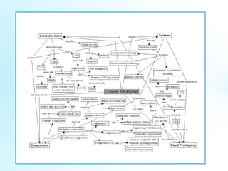
1
 Use of computer systems to
assist in the creation,
modification, analysis, and
optimization of a design
 Typical tools:
◦ Tolerance analysis
◦ Mass property calculations
◦ Finite-element modeling and
visualization
 Defines the geometry of the
design
 Use of computer systems to
plan, manage, and control
manufacturing operations
 Direct or indirect computer
interface with the plant’s
production resources
 Numerical control of
machine tools
 Programming of robots
 Use of computer systems
to analyze CAD geometry
 Allows designer to
simulate and study how
the product will behave,
allowing for optimization
 Finite-element method
(FEM)
◦ Divides model into
interconnected elements
◦ Solves continuous field
problems
 Two types of activities: synthesis and analysis
 Synthesis is largely qualitative and hard to
capture on computer
 Analysis can be greatly enhanced with
computers
 Once analysis is complete, design evaluation-
rapid prototyping
 Software packages for design optimization
 Major component is
hardware and software
allowing shape
manipulation
 Hardware includes graphic
devices and their
peripherals for input and
output operations
 Software includes packages
that manipulate or analyze
shapes according to user
interaction
 Graphic device is composed of a display
processing unit, a display device, and
one or more input devices
 Input devices:
◦ Mouse
◦ Space ball
◦ Data tablet with a puck or stylus
◦ Keyboard
 Output Devices:
◦ Plotters
◦ Color laser printers
 CAD software allows the designer to create
and manipulate a shape interactively and
store it
 CAM software plans, manages and controls
the operations of a manufacturing site
 CAE software analyzes design geometry,
allowing designer to study product behavior
 User interface is similar to Windows
 Employs component technology, in which
best key software elements are selected from
among available software
 Use object-oriented technology, which
modularizes the program
 Capable of either parametric or variational
modeling
 Internet support
• CAD/CAM = Computer Aided Design and
Computer Aided Manufacturing. It is the
technology concerned with the use of
computers to perform design and
manufacturing functions.
11
• CAD can be defined as the use of computer
systems to perform certain functions in the
design process.
• CAM is the use of computer systems to
plan, manage and control the operations of
manufacturing plant through either direct
or indirect computer interface with the
plant’s production resources.
12
 Layer by layer fabrication
of three-dimensional
physical models from CAD
 Fast and inexpensive
alternative for producing
prototypes and functional
models
 Build parts in thin layers
 Minimum operation time;
typically runs unattended
Rapid Prototyping
has surgical
applications
 .STL is standard file
format for all U.S. rapid
prototyping systems
 Preprocessing prepares
.STL file for various
rapid prototyping
systems
 Build process can last
from a few hours to
several days
 Post processing:
removal of part from
machine, support
removal, sanding
“A computer-controlled laser beam is scanned across the surface
of a vat of liquid photopolymer, instantly solidifying the liquid at
each point of contact. Using data generated from a CAD file,
individual cross-sections of the three-dimensional geometry are
solidified in turn to build up a solid part layer by layer. In this
way even highly complex geometries can be built in a few hours
without requiring any tools. “
From CAM definition, the application of
CAM falls into two broad categories:
1. Computer monitoring and control .
18
Computer Process
Process
data
2. Manufacturing support application .
19
Control signals
Computer Mfg
operatio
ns
Process data
In order to establish the scope and
definition of CAD/CAM in an engineering
environment and identify existing and future
related tools, a study of a typical product
cycle is necessary. The following Figure
shows a flowchart of such a cycle.
20
21
The Manufacturing Process
The Design Process
Synthesis
Analysis The CAD Process
The CAM Process
Design
needs
Design
definitions,
specifications,
and requirements
Collecting
relevant design
information and
feasibility study
Design
conceptualization
Design
modeling and
simulation
Design
analysis
Design
optimization
Design
evaluation
Design
documentation and
communication
Process
planning
Order
materials
Design and
procurement of
new tools
Production
planning
NC, CNC, DNC
programming
Production
Quality
control
Packaging
Marketing
Shipping
Typical Product Life Cycle
 The product begins with a need which is
identified based on customers' and markets'
demands.
 The product goes through two main
processes from the idea conceptualization
to the finished product:
1. The design process.
2. The manufacturing process.
The main sub-processes that constitute the
design process are:
1. Synthesis.
2. Analysis.
22
23
Delineation of
geometric
model
Definition
translator
Geometric
model
Design and
Analysis
algorithms
Drafting and
detailing
Documentation
To CAM Process
Interface
algorithms
Design changes
24
Design phase Required CAD tools
Design conceptualization Geometric modeling techniques;
Graphics aids; manipulations; and
visualization
Design modeling and simulation Same as above; animation; assemblies;
special modeling packages.
Design analysis Analysis packages; customized
programs and packages.
Design optimization Customized applications; structural
optimization.
Design evaluation Dimensioning; tolerances; BOM; NC.
Design communication and
documentation
Drafting and detailing…
25
Geometric
model
Interface
algorithms
Process
planning
Inspection
Assembly
Packaging
To shipping and marketing
NC programs
26
Manufacturing phase Required CAM tools
Process planning CAPP techniques; cost
analysis; material and
tooling specification.
Part programming NC programming
Inspection CAQ; and Inspection
software
Assembly Robotics simulation and
programming
CAM Tools Required to Support the Design Proc
Automation can be defined as the
technology concerned with the application
of complex mechanical, electronic, and
computer-based systems in the operation
and control of manufacturing systems.
27
28
TTypes of Manufacturing Systems
1. Continuous-flow processes. Continuous dedicated production of
large amount of bulk product. Continuous manufacturing is
represented by chemicals, plastics, petroleum, and food industries.
2. Mass production of discrete products. Dedicated production of
large quantities of one product (with perhaps limited model
variations). Examples include automobiles, appliances and engine
blocks.
3. Batch production. Production of medium lot sizes of the same
product. The lot may be produced once or repeated periodically.
Examples: books, clothing and certain industrial machinery.
4. Job-shop production. Production of low quantities, often one of a
kind, of specialized products. The products are often customized
and technologically complex. Examples: prototypes, aircraft,
machine tools and other equipment.
29
Production
quantity
Continuous-
flow
production Mass
production
Batch
production
Job shop
production
Product variety
30
Category Automation achievements
Continuous-flow process •Flow process from beginning to end
•Sensors technology available to measure
important process variables
•Use of sophisticated control and optimization
strategies
•Fully computer automated lines
Mass production of discrete products •Automated transfer machines
•Dial indexing machines
•Partially and fully automated assembly lines
•Industrial robots for spot welding, part handling,
machine loading, spray painting, etc.
•Automated material handling systems
•Computer production monitoring
Batch production •Numerical control (NC), direct numerical
control (DNC), computer numerical control
(CNC).
•Adaptive control machining
•Robots for arc welding, parts handling, etc.
•CIM systems.
Job shop production •Numerical control, computer numerical control
31
Most of the automated production systems implemented today
make use of computers. CAD/CAM in addition to its particular
emphasis on the use of computer technology, is also
distinguished by the fact that it includes not only the
manufacturing operations but also the design and planning
functions that precede manufacturing.
To emphasize the differences in scope between automation and
CAD/CAM, consider the following mathematical model:
Computer Technology in Automation
• Greater flexibility.
• Reduced lead times.
• Reduced inventories.
• Increased Productivity.
• Improved customer
service.
• Improved quality.
• Improved
communications with
suppliers.
32
• Better product design.
• Greater manufacturing
control.
• Supported integration.
• Reduced costs.
• Increased utilization.
• Reduction of machine
tools.
• Less floor space.
Introduction to cad/cam

Introduction to cad/cam

  • 1.
  • 2.
     Use ofcomputer systems to assist in the creation, modification, analysis, and optimization of a design  Typical tools: ◦ Tolerance analysis ◦ Mass property calculations ◦ Finite-element modeling and visualization  Defines the geometry of the design
  • 3.
     Use ofcomputer systems to plan, manage, and control manufacturing operations  Direct or indirect computer interface with the plant’s production resources  Numerical control of machine tools  Programming of robots
  • 4.
     Use ofcomputer systems to analyze CAD geometry  Allows designer to simulate and study how the product will behave, allowing for optimization  Finite-element method (FEM) ◦ Divides model into interconnected elements ◦ Solves continuous field problems
  • 5.
     Two typesof activities: synthesis and analysis  Synthesis is largely qualitative and hard to capture on computer  Analysis can be greatly enhanced with computers  Once analysis is complete, design evaluation- rapid prototyping  Software packages for design optimization
  • 6.
     Major componentis hardware and software allowing shape manipulation  Hardware includes graphic devices and their peripherals for input and output operations  Software includes packages that manipulate or analyze shapes according to user interaction
  • 8.
     Graphic deviceis composed of a display processing unit, a display device, and one or more input devices  Input devices: ◦ Mouse ◦ Space ball ◦ Data tablet with a puck or stylus ◦ Keyboard  Output Devices: ◦ Plotters ◦ Color laser printers
  • 9.
     CAD softwareallows the designer to create and manipulate a shape interactively and store it  CAM software plans, manages and controls the operations of a manufacturing site  CAE software analyzes design geometry, allowing designer to study product behavior
  • 10.
     User interfaceis similar to Windows  Employs component technology, in which best key software elements are selected from among available software  Use object-oriented technology, which modularizes the program  Capable of either parametric or variational modeling  Internet support
  • 11.
    • CAD/CAM =Computer Aided Design and Computer Aided Manufacturing. It is the technology concerned with the use of computers to perform design and manufacturing functions. 11
  • 12.
    • CAD canbe defined as the use of computer systems to perform certain functions in the design process. • CAM is the use of computer systems to plan, manage and control the operations of manufacturing plant through either direct or indirect computer interface with the plant’s production resources. 12
  • 13.
     Layer bylayer fabrication of three-dimensional physical models from CAD  Fast and inexpensive alternative for producing prototypes and functional models  Build parts in thin layers  Minimum operation time; typically runs unattended Rapid Prototyping has surgical applications
  • 16.
     .STL isstandard file format for all U.S. rapid prototyping systems  Preprocessing prepares .STL file for various rapid prototyping systems  Build process can last from a few hours to several days  Post processing: removal of part from machine, support removal, sanding
  • 17.
    “A computer-controlled laserbeam is scanned across the surface of a vat of liquid photopolymer, instantly solidifying the liquid at each point of contact. Using data generated from a CAD file, individual cross-sections of the three-dimensional geometry are solidified in turn to build up a solid part layer by layer. In this way even highly complex geometries can be built in a few hours without requiring any tools. “
  • 18.
    From CAM definition,the application of CAM falls into two broad categories: 1. Computer monitoring and control . 18 Computer Process Process data
  • 19.
    2. Manufacturing supportapplication . 19 Control signals Computer Mfg operatio ns Process data
  • 20.
    In order toestablish the scope and definition of CAD/CAM in an engineering environment and identify existing and future related tools, a study of a typical product cycle is necessary. The following Figure shows a flowchart of such a cycle. 20
  • 21.
    21 The Manufacturing Process TheDesign Process Synthesis Analysis The CAD Process The CAM Process Design needs Design definitions, specifications, and requirements Collecting relevant design information and feasibility study Design conceptualization Design modeling and simulation Design analysis Design optimization Design evaluation Design documentation and communication Process planning Order materials Design and procurement of new tools Production planning NC, CNC, DNC programming Production Quality control Packaging Marketing Shipping Typical Product Life Cycle
  • 22.
     The productbegins with a need which is identified based on customers' and markets' demands.  The product goes through two main processes from the idea conceptualization to the finished product: 1. The design process. 2. The manufacturing process. The main sub-processes that constitute the design process are: 1. Synthesis. 2. Analysis. 22
  • 23.
    23 Delineation of geometric model Definition translator Geometric model Design and Analysis algorithms Draftingand detailing Documentation To CAM Process Interface algorithms Design changes
  • 24.
    24 Design phase RequiredCAD tools Design conceptualization Geometric modeling techniques; Graphics aids; manipulations; and visualization Design modeling and simulation Same as above; animation; assemblies; special modeling packages. Design analysis Analysis packages; customized programs and packages. Design optimization Customized applications; structural optimization. Design evaluation Dimensioning; tolerances; BOM; NC. Design communication and documentation Drafting and detailing…
  • 25.
  • 26.
    26 Manufacturing phase RequiredCAM tools Process planning CAPP techniques; cost analysis; material and tooling specification. Part programming NC programming Inspection CAQ; and Inspection software Assembly Robotics simulation and programming CAM Tools Required to Support the Design Proc
  • 27.
    Automation can bedefined as the technology concerned with the application of complex mechanical, electronic, and computer-based systems in the operation and control of manufacturing systems. 27
  • 28.
    28 TTypes of ManufacturingSystems 1. Continuous-flow processes. Continuous dedicated production of large amount of bulk product. Continuous manufacturing is represented by chemicals, plastics, petroleum, and food industries. 2. Mass production of discrete products. Dedicated production of large quantities of one product (with perhaps limited model variations). Examples include automobiles, appliances and engine blocks. 3. Batch production. Production of medium lot sizes of the same product. The lot may be produced once or repeated periodically. Examples: books, clothing and certain industrial machinery. 4. Job-shop production. Production of low quantities, often one of a kind, of specialized products. The products are often customized and technologically complex. Examples: prototypes, aircraft, machine tools and other equipment.
  • 29.
  • 30.
    30 Category Automation achievements Continuous-flowprocess •Flow process from beginning to end •Sensors technology available to measure important process variables •Use of sophisticated control and optimization strategies •Fully computer automated lines Mass production of discrete products •Automated transfer machines •Dial indexing machines •Partially and fully automated assembly lines •Industrial robots for spot welding, part handling, machine loading, spray painting, etc. •Automated material handling systems •Computer production monitoring Batch production •Numerical control (NC), direct numerical control (DNC), computer numerical control (CNC). •Adaptive control machining •Robots for arc welding, parts handling, etc. •CIM systems. Job shop production •Numerical control, computer numerical control
  • 31.
    31 Most of theautomated production systems implemented today make use of computers. CAD/CAM in addition to its particular emphasis on the use of computer technology, is also distinguished by the fact that it includes not only the manufacturing operations but also the design and planning functions that precede manufacturing. To emphasize the differences in scope between automation and CAD/CAM, consider the following mathematical model: Computer Technology in Automation
  • 32.
    • Greater flexibility. •Reduced lead times. • Reduced inventories. • Increased Productivity. • Improved customer service. • Improved quality. • Improved communications with suppliers. 32 • Better product design. • Greater manufacturing control. • Supported integration. • Reduced costs. • Increased utilization. • Reduction of machine tools. • Less floor space.