The document discusses reverse engineering and provides details on the process. It is summarized as follows:
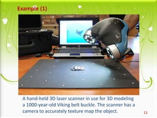
[1] Reverse engineering involves scanning a physical part to create a 3D CAD model and then manufacturing a new part. It is used to provide replacement parts when technical data is lost or to duplicate competitor's parts.
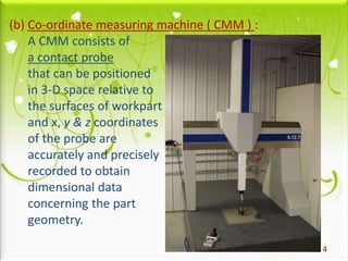
[2] The main steps are obtaining the part geometry through 3D scanning, identifying the material, generating a 3D CAD model, and manufacturing the new part. Geometry can be captured through contact methods like CMM or non-contact like 3D laser scanning. Material identification uses techniques like mass spectrometry and SEM.
[3] Once scanned, reverse engineering software converts the 3D image
![3
STEP[1]
• OBTAINING THE PART GEOMETRY
STEP[2]
• MATERIAL IDENTIFICATION
STEP[3]
• 3-D CAD MODEL GENERATION
STEP[4]
• MANUFACTURING OF A PART
STEPS IN REVERSE ENGINEERING :](https://image.slidesharecdn.com/revengg-150402000138-conversion-gate01/85/Rev-engg-3-320.jpg)
![STEP [1] OBTAINING THE PART GEOMETRY :-
It involves ‘automatic digitizing’ of the
surface of a physically existing object i.e.
3-D image of the object is obtained by
scanning the entire object.
There are two ways of digitizing:
[1] Contact type digitizing.
[2] Non-contact type digitizing.
4](https://image.slidesharecdn.com/revengg-150402000138-conversion-gate01/85/Rev-engg-4-320.jpg)
![5
[1]Contact Type digitizing:
In this method, there is physical contact
between the measuring instrument and the surface
being measured to record as many dimensions as
possible.
It includes following instruments.
(a) Hand Tools :
Micrometers, Vernier calipers and Gauges
These are used to capture the critical
dimensions needed to generate a part drawing.](https://image.slidesharecdn.com/revengg-150402000138-conversion-gate01/85/Rev-engg-5-320.jpg)
![7
[2] Non-Contact Type digitizing:
Data acquisition is done without physically
touching the part.
It uses structured lighting and reflection
from the object to get the 3-D image
of the object.
It consists of following techniques :-
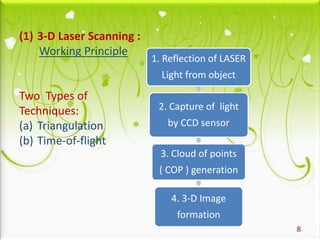
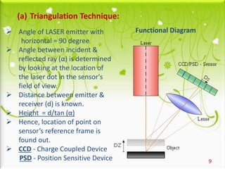
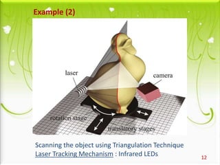
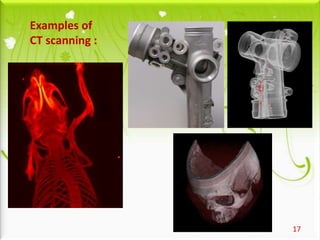
(1) 3-D Laser Scanning
(2) Industrial CT Scanning](https://image.slidesharecdn.com/revengg-150402000138-conversion-gate01/85/Rev-engg-7-320.jpg)
![15
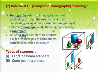
(i) Fan/Line beam scanners-[Translate] :
These are Line scanners.
It is the first generation of industrial CT Scanners.
X-rays are produced and the beam is collimated to create a line.
The X-ray line beam is then translated across the part and data
is collected by the detector in the form of 2-D image slices.
The data is then reconstructed to create a 3-D Volume rendering
of the part.
Detector
Collimated beam
of X-rays](https://image.slidesharecdn.com/revengg-150402000138-conversion-gate01/85/Rev-engg-15-320.jpg)
![16
(ii) Cone beam scanners-[Rotate] :
During the CT scan, part is
placed on a rotary table.
As the part rotates the cone
of X-rays produce about
1300 2D images which are
collected by the detector.
The 2D images are then
processed to create a 3D
Volume rendering of the
external and internal
geometries of the part.](https://image.slidesharecdn.com/revengg-150402000138-conversion-gate01/85/Rev-engg-16-320.jpg)
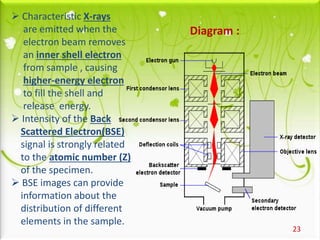
![19
STEP[2] MATERIAL IDENTIFICATION :-
Identifying the material composition of the
existing part is the second most important task.
There are several well-established non-destructive
and destructive techniques to find the composition
of part material.
(1) Mass Spectrometry
(2) Scanning Electron Microscope (SEM)](https://image.slidesharecdn.com/revengg-150402000138-conversion-gate01/85/Rev-engg-19-320.jpg)
![20
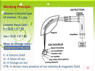
(1) Mass Spectrometry :
A sample loaded on to the mass spectrometer
undergoes vaporization. Hence,
it is also called as Vapour Phase Chemistry.
We get spectral lines of various masses of components.
Hence, it is called Mass Spectrometry.
It measures the mass-to-charge ratio[m/Q]of
charged particles(ions) created in the process.
It is used for determining masses of particles,
for determining the elemental composition
of a sample or molecule.](https://image.slidesharecdn.com/revengg-150402000138-conversion-gate01/85/Rev-engg-20-320.jpg)
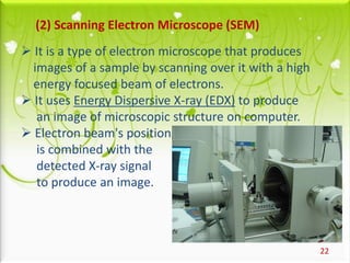
![24
STEP [3] 3-D CAD MODEL GENERATION :-
After scanning, we get 3-D image of a part.
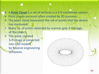
It is converted into 3-D CAD model by Reverse engineering
software such as Geomagics ,Imageware Surfacer,
Magics, Pro/Scan Tools ,Rapidform and STRIM
which are specially developed for this purpose.
STEP [4] MANUFACTURING OF A PART :-
Once the 3-D CAD model is generated, it is manufactured
by using various manufacturing techniques.
Mainly, Rapid Prototyping is used for this purpose.](https://image.slidesharecdn.com/revengg-150402000138-conversion-gate01/85/Rev-engg-24-320.jpg)