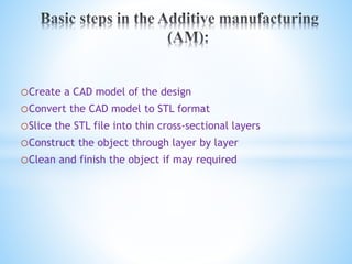
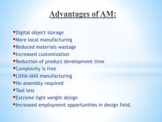
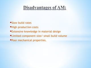
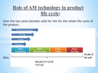
3. Subtractive manufacturing is a process by which 3D objects are
constructed by successively cutting material away from a solid block of
material. It is also known to us as “Conventional manufacturing”.
Additive Manufacturing is a process by which 3D objects are
constructed by successively depositing material in layers such that it
becomes a predesigned shape.
Modern 3D printing has always been very useful for rapid prototype
development but it is starting to make its impact on the manufacturing
world as well.
4. A prototype is an early sample, model, or release of a
product built to test a concept or process to estimate the
behavior of original product under working conditions.
Rapid prototyping(RP) is a group of techniques used to
quickly fabricate a scale model of a physical part or assembly
using three-dimensional computer aided design (CAD) data.
5. oCreate a CAD model of the design
oConvert the CAD model to STL format
oSlice the STL file into thin cross-sectional layers
oConstruct the object through layer by layer
oClean and finish the object if may required
6. Digital object storage
More local manufacturing
Reduced materials wastage
Increased customization
Reduction of product development time
Complexity is free
Little-skill manufacturing
No assembly required
Tool less
Extreme light weight design
Increased employment opportunities in design field.
7. Slow build rates
High production costs
Extensive knowledge in material design
Limited component size/ small build volume
Poor mechanical properties.
8. This timeline lays out past, present and potential future AM
developments and applications.
(From Royal Academy of Engineering- UK )
9. Over the last years became valid for the for the whole life cycle of
the product.
Idea
10.
11.
12. Fig: Hopkinson and Dickens (2003) Cost Model Compared to
Injection Molding
14. It is the first and foremost 3D printing process.
SL is a laser-based process that works on the photo polymerization.
Photo polymerization reactions are chain-growth polymerizations
which are initiated by the absorption of visible or ultraviolet light.
The light may be absorbed either directly by the reactant monomer
(direct photo polymerization), or else by a photo sensitizer which
absorbs the light and then transfers energy to the monomer.
15.
16. Stereo lithography (SL) prototypes are constructed from a liquid
photopolymer that is selectively cured using a solid-state laser.
The process begins with a 3D CAD file, which is mathematically sliced
into 2D cross sections.
With the build platform positioned just below the surface of the
photopolymer, a scanning system is used to draw the first cross section on
the surface of the photopolymer, which adheres to the platform.
When the layer is complete, the elevator assembly lowers the platform
into the vat and the next layer is drawn, with each new layer adhering to
the previous one.
The process repeats itself until the object is completed.
Actual build times can range from under an hour to over a day,
depending on the photopolymer, laser power, and the object geometry.
17. Prototypes for design, analysis, verification and functional
testing.
Parts for prototype tooling and low volume production tooling.
Patterns for investment casting, sand casting and molding.
Models for conceptualization and presentation.
18. Procedure:
The SLS process creates 3D objects, layer by layer, from CAD-
data using powdered materials with heat generated by CO2 laser
within the sinteration system.
CAD data files in the .STL format are first transferred to the
sinteration systems where they are sliced.
From this point, the SLS process begins and operate as follows:
20. The interaction of the laser beam with the powder elevates the
temperature to the point of melting, fusing the powder particles
to form a solid mass.
The intensity of laser beam is modulated to melt the powder
only in areas defined by the part’s geometry.
Surrounding powder remains a loose compact and serves as
natural supports.
When the cross-section is completely “drawn”, an additional
layer of powder is deposited via a roller mechanism on top of the
previously scanned layer.
This prepares the next layer for scanning.
By successive layers of powder deposition, the process is
repeated until the part is completed.
21. Concept models: Physical representation of designs used to
review design ideas, form and style.
Functional models and working prototypes: Parts that can
withstand limited functional testing, or fit and operate within an
assembly.
Polycarbonate patterns(rapid casting): These patterns are
used in investment casting process rather than wax patterns.
These patterns are durable and heat resistant.
Metal tools: direct rapid prototype of tools of molds for small
and short production runs.
22. The principle of the FDM process is based on the surface
chemistry, thermal energy and layer manufacturing technology.
The material in filament form(or unwounded or uncoiled metal
wire form) is melted in a specially designed head, which extrudes
it through the nozzle.
As it is extruded, it is cooled and thus solidifies to for the
object.
The object is built layer by layer, like the other RP systems.