Download as PDF, PPTX
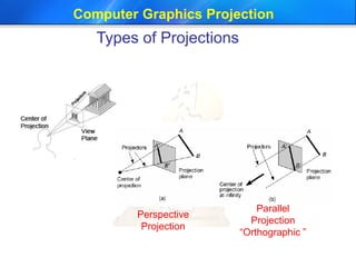
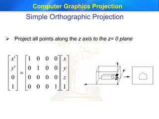
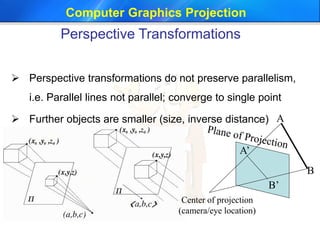
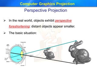
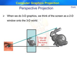
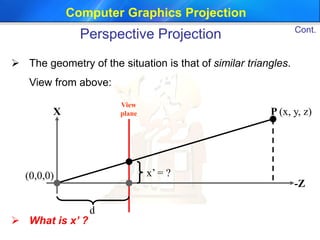
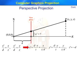
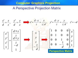
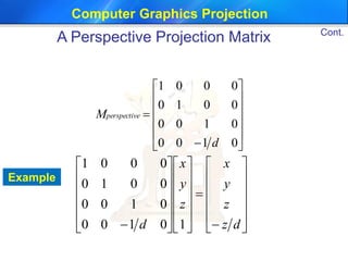
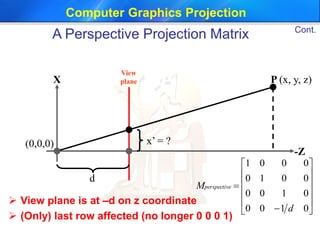
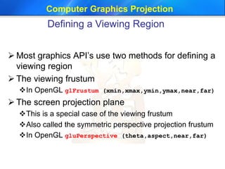
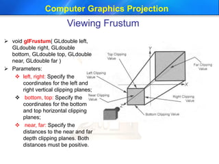


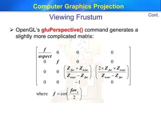


This document discusses different types of projections used in computer graphics, including perspective and parallel projections. It describes orthographic projection, which projects points along the z-axis onto the z=0 plane. Perspective projection is also covered, including how it creates the effect of objects appearing smaller with distance using similar triangles. The document provides the equation for a perspective projection matrix and an example. It concludes by discussing defining a viewing region or frustum using functions like glFrustum and gluPerspective in OpenGL.


![MODULE-5 notes [BCG402-CG&V] PART-B.pdf](https://cdn.slidesharecdn.com/ss_thumbnails/module-5notesbcg402-cgvpart-b-250630054728-c1eaacea-thumbnail.jpg?width=640&height=640&fit=bounds)


