This document discusses 3D computer graphics concepts including:
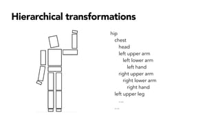
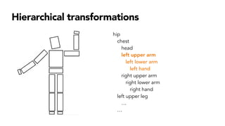
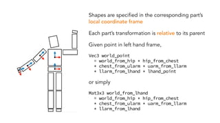
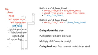
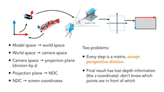
- Hierarchical transformations that allow representing 3D objects as a tree of parts related by transformations.
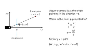
- Perspective projection which projects 3D points onto a 2D image plane based on a pinhole camera model.
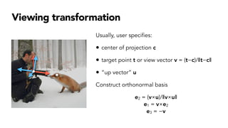
- The viewing transformation which orients the camera in the 3D world.
- The graphics pipeline which transforms 3D models through multiple coordinate systems until rasterization on the 2D screen.
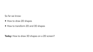
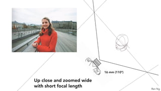
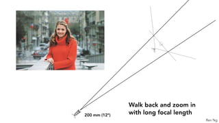
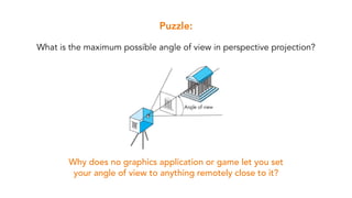
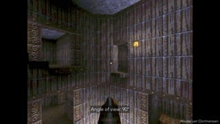
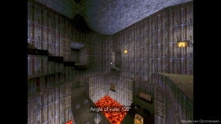
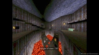
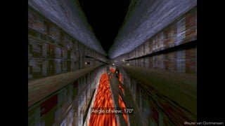
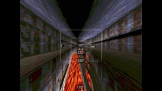
- Limitations of perspective projection like the maximum field of view and loss of depth information after projection.
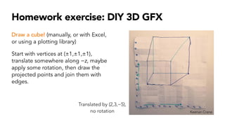
- A homework exercise to manually project a translated and rotated 3D cube.

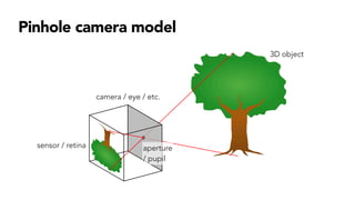
![Camera → world: M = [e1 e2 e3 c]
World → camera: M−1
Once point is in camera space, projected point =
[
xd/z
yd/z]
Model space
World space
Camera space](https://image.slidesharecdn.com/6-240329140633-9402aa6f/85/6-Perspective-Projection-pdf-16-320.jpg)
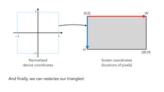
![Choose transformation so that points in field of view fall inside [−1,1] × [−1,1]
(ℓ,b)
(r,b)
(ℓ,t)
(r,t)
−1
−1
1
1
“Normalized
device coordinates”
Coordinates after
perspective division
(Actually there’s a bit more in NDC… Will correct later!)](https://image.slidesharecdn.com/6-240329140633-9402aa6f/85/6-Perspective-Projection-pdf-20-320.jpg)


![MODULE-5 notes [BCG402-CG&V] PART-B.pdf](https://cdn.slidesharecdn.com/ss_thumbnails/module-5notesbcg402-cgvpart-b-250630054728-c1eaacea-thumbnail.jpg?width=640&height=640&fit=bounds)


