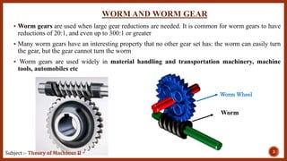
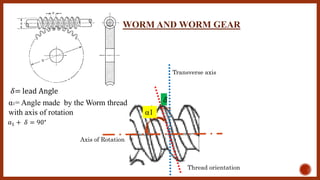
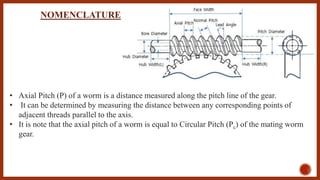
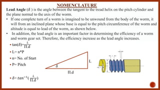
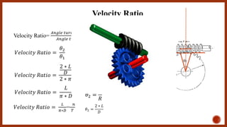
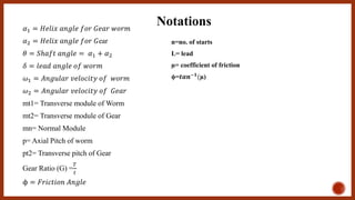
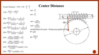
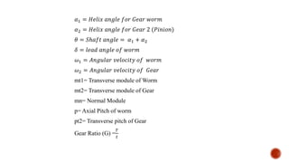
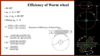
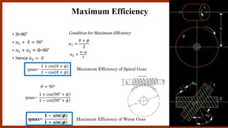
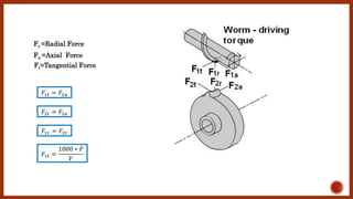
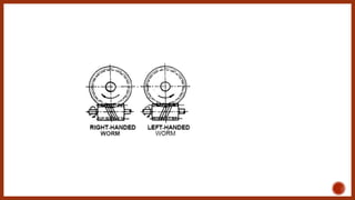
Sanjivani Rural Education Society’s
Sanjivani College of Engineering, Kopargaon-423603
( An Autonomous Institute Affiliated to Savitribai Phule Pune University, Pune)
NAAC ‘A’ Grade Accredited, ISO 9001:2015 Certified
Subject :- Theory of Machines II
T.E. Mechanical (302043)
Unit 2
2.3 WORM AND WORM WHEEL
By
Prof. K. N. Wakchaure(Asst Professor)
Department of Mechanical Engineering
Sanjivani College of Engineering
(An Autonomous Institute)
Kopargaon, Maharashtra
Email: wakchaurekiranmech@Sanjivani.org.in Mobile:- +91-7588025393
WORM AND WORM GEAR
 Worm gears are used when large gear reductions are needed. It is common for worm gears to have
reductions of 20:1, and even up to 300:1 or greater
 Many worm gears have an interesting property that no other gear set has: the worm can easily turn
the gear, but the gear cannot turn the worm
 Worm gears are used widely in material handling and transportation machinery, machine
tools, automobiles etc
3Subject :- Theory of Machines II
Worm Wheel
Worm
Axis of Rotation
Transverse axis
Thread orientation
𝛿
α1
𝛿= lead Angle
α1= Angle made by the Worm thread
with axis of rotation
α1 + 𝛿 = 90°
WORM AND WORM GEAR
• Axial Pitch (P) of a worm is a distance measured along the pitch line of the gear.
• It can be determined by measuring the distance between any corresponding points of
adjacent threads parallel to the axis.
• It is note that the axial pitch of a worm is equal to Circular Pitch (Pc) of the mating worm
gear.
NOMENCLATURE
Lead ( L ) is the linear distance through which a point on a thread moves ahead in one revolution of
the worm.
For single start threads, lead is equal to the axial pitch. Therefore, lead can be calculated as the
product of axial pitch and number of starts.
L=n*P
P=axial Pitch
n= no. of Starts
NOMENCLATURE
For Single Start: L=P
For Double Start: L=2*P
For Triple StartL =3*P
 tan(𝛿)=
𝐿
Π.d
 L= n*P
 n= No. of Start
 P= Pitch
 𝛿= 𝑡𝑎𝑛−1
(
𝐿
Π.d
)
Π.d
L
𝛿
Lead Angle (𝛿 ) is the angle between the tangent to the tread helix on the pitch cylinder and
the plane normal to the axis of the worm.
• If one complete turn of a worm is imagined to be unwound from the body of the worm, it
will from an inclined plane whose base is equal to the pitch circumference of the worm and
altitude is equal to lead of the worm, as shown below.
• In addition, the lead angle is an important factor in determining the efficiency of a worm
and worm gear set. Therefore, the efficiency increase as the lead angle increases.
NOMENCLATURE
L
θ2
Velocity Ratio=
𝐴𝑛𝑔𝑙𝑒 𝑡𝑢𝑟𝑛𝑒𝑑 𝑏𝑦 𝑤𝑜𝑟𝑚 𝑔𝑒𝑎𝑟 𝑖𝑛 1 𝑟𝑒𝑣𝑜𝑙𝑢𝑡𝑖𝑜𝑛
𝐴𝑛𝑔𝑙𝑒 𝑡𝑢𝑟𝑛𝑒𝑑 𝑏𝑦 𝑤𝑜𝑟𝑚 𝑖𝑛 1 𝑟𝑒𝑣𝑜𝑙𝑢𝑡𝑖𝑜𝑛
𝑉𝑒𝑙𝑜𝑐𝑖𝑡𝑦 𝑅𝑎𝑡𝑖𝑜 =
𝜃2
𝜃1 sin (
𝜃2
2
)=
𝐿/2
𝑅
As
𝜃2
2
is vey small angle sin (
𝜃2
2
)≅
𝜃2
2
Hence
𝜃2
2
=
𝐿/2
𝑅
𝜃2 =
𝐿
𝑅
𝜃2 =
2 ∗ 𝐿
𝐷
𝑉𝑒𝑙𝑜𝑐𝑖𝑡𝑦 𝑅𝑎𝑡𝑖𝑜 =
2 ∗ 𝐿
𝐷
2 ∗ 𝜋
𝑉𝑒𝑙𝑜𝑐𝑖𝑡𝑦 𝑅𝑎𝑡𝑖𝑜 =
𝐿
𝜋 ∗ 𝐷
Velocity Ratio
𝑉𝑒𝑙𝑜𝑐𝑖𝑡𝑦 𝑅𝑎𝑡𝑖𝑜 =
𝐿
𝜋∗𝐷
=
𝑛
𝑇
𝛼1 = 𝐻𝑒𝑙𝑖𝑥 𝑎𝑛𝑔𝑙𝑒 𝑓𝑜𝑟 𝐺𝑒𝑎𝑟 𝑤𝑜𝑟𝑚
𝛼2 = 𝐻𝑒𝑙𝑖𝑥 𝑎𝑛𝑔𝑙𝑒 𝑓𝑜𝑟 𝐺ear
𝜃 = 𝑆ℎ𝑎𝑓𝑡 𝑎𝑛𝑔𝑙𝑒 = 𝛼1 + 𝛼2
𝛿 = 𝑙𝑒𝑎𝑑 𝑎𝑛𝑔𝑙𝑒 𝑜𝑓 𝑤𝑜𝑟𝑚
𝜔1 = 𝐴𝑛𝑔𝑢𝑙𝑎𝑟 𝑣𝑒𝑙𝑜𝑐𝑖𝑡𝑦 𝑜𝑓 𝑤𝑜𝑟𝑚
𝜔2 = 𝐴𝑛𝑔𝑢𝑙𝑎𝑟 𝑣𝑒𝑙𝑜𝑐𝑖𝑡𝑦 𝑜𝑓 𝐺𝑒𝑎𝑟
mt1= Transverse module of Worm
mt2= Transverse module of Gear
mn= Normal Module
p= Axial Pitch of worm
pt2= Transverse pitch of Gear
Gear Ratio (G) =
𝑇
𝑡
ϕ = 𝐹𝑟𝑖𝑐𝑡𝑖𝑜𝑛 𝐴𝑛𝑔𝑙𝑒
Notations
n=no. of starts
L= lead
µ= coefficient of friction
ϕ=𝒕𝒂𝒏−𝟏(µ)
Center Distance
CD
Center Distance = CD= r+R =
𝑑
2
+
𝐷
2
CD =
𝑚𝑡1∗𝑡
2
+
𝑚𝑡2∗𝑇
2
mt1 =
𝑚𝑛
cos(𝛼1)
mt2 =
𝑚𝑛
cos(𝛼2)
CD =
𝑚𝑛
2
𝑡
cos(𝛼1)
+
𝑇
cos(𝛼2)
CD=
𝑚𝑛∗𝑡
2
1
cos(𝛼1)
+
𝐺
cos(𝛼2)
CD=
𝑚𝑛∗𝑡
2
1
cos(90−𝛿)
+
𝐺
cos(𝛼2)
CD=
𝑚𝑛∗𝑡
2
1
sin(𝛿)
+
𝐺
cos(𝛿)
CD=
𝑚𝑛∗𝑡
2∗cos(𝛿)
cos(𝛿)
sin(𝛿)
+ 𝐺
CD=
𝑚𝑛∗𝑡
2∗cos(𝛿)
cos(𝛿)
sin(𝛿)
+ 𝐺
CD=
mt2∗ cos(𝛿) ∗𝑡
2∗cos(𝛿)
cot(𝛿) + 𝐺
CD=
mt2∗𝑡
2
∗ cot(𝛿) + 𝐺
Axial Pitch of worm =Transverse pitch of Gear
P= pt2
D =
𝑃𝑡2∗𝑇
π
mt1 =
𝑑
t
mt1 =
𝐷
T
𝛼1 = 𝐻𝑒𝑙𝑖𝑥 𝑎𝑛𝑔𝑙𝑒 𝑓𝑜𝑟 𝐺𝑒𝑎𝑟 𝑤𝑜𝑟𝑚
𝛼2 = 𝐻𝑒𝑙𝑖𝑥 𝑎𝑛𝑔𝑙𝑒 𝑓𝑜𝑟 𝐺𝑒𝑎𝑟 2 (𝑃𝑖𝑛𝑖𝑜𝑛)
𝜃 = 𝑆ℎ𝑎𝑓𝑡 𝑎𝑛𝑔𝑙𝑒 = 𝛼1 + 𝛼2
𝛿 = 𝑙𝑒𝑎𝑑 𝑎𝑛𝑔𝑙𝑒 𝑜𝑓 𝑤𝑜𝑟𝑚
𝜔1 = 𝐴𝑛𝑔𝑢𝑙𝑎𝑟 𝑣𝑒𝑙𝑜𝑐𝑖𝑡𝑦 𝑜𝑓 𝑤𝑜𝑟𝑚
𝜔2 = 𝐴𝑛𝑔𝑢𝑙𝑎𝑟 𝑣𝑒𝑙𝑜𝑐𝑖𝑡𝑦 𝑜𝑓 𝐺𝑒𝑎𝑟
mt1= Transverse module of Worm
mt2= Transverse module of Gear
mn= Normal Module
p= Axial Pitch of worm
pt2= Transverse pitch of Gear
Gear Ratio (G) =
𝑇
𝑡
 Θ=90°
 α1 + 𝛿 = 90°
 α1 + α2 = Θ=90°
 Hence α2 = 𝛿
 ղ=
cos 𝛿+ϕ ∗𝑐𝑜𝑠( 90−𝛿 )
𝑐𝑜𝑠 90−𝛿 −ϕ ∗𝑐𝑜𝑠( 𝛿 )
 ղ=
cos 𝛿+ϕ ∗𝑠𝑖𝑛( 𝛿 )
𝑠𝑖𝑛 𝛿+ϕ ∗𝑐𝑜𝑠 𝛿
 ղ=
𝑡𝑎𝑛( 𝛿 )
𝑡𝑎𝑛 𝛿+ϕ
ղ=
)cos 𝛼2 + 𝜙 ∗ 𝑐𝑜𝑠(𝛼1
𝑐𝑜𝑠 𝛼1 − 𝜙 ∗ 𝑐𝑜𝑠 𝛼2
Efficiency of Worm wheel
Equation of Efficiency of Spiral Gear
 Θ=90°
 α1 + 𝛿 = 90°
 α1 + α2 = Θ=90°
 Hence α2 = 𝛿
Maximum Efficiency
ղmax=
1 + cos 𝜃 + 𝜙
1 − cos 𝜃 + 𝜙
𝜃 = 90°
ղmax=
1 + cos 90° + 𝜙
1 − cos 90° + 𝜙
ղmax=
𝟏 − 𝒔𝒊𝒏 𝝓
𝟏 + 𝒔𝒊𝒏 𝝓
Condition for Maximum Efficiency
𝛼1 =
𝜃 + 𝜙
2
𝛼2 =
𝜃−𝜙
2
Maximum Efficiency of Spiral Gear
Maximum Efficiency of Worm Gear
𝐹1𝑡 = 𝐹2𝑎
𝐹2𝑡 = 𝐹1𝑎
𝐹1𝑟 = 𝐹2𝑟
𝐹1𝑡 =
1000 ∗ 𝑃
𝑉
Fa =Axial Force
Fr =Radial Force
Ft=Tangential Force
16
Subject :- Theory of Machines II

2.3 worm and worm wheel

  • 2.
    Sanjivani Rural EducationSociety’s Sanjivani College of Engineering, Kopargaon-423603 ( An Autonomous Institute Affiliated to Savitribai Phule Pune University, Pune) NAAC ‘A’ Grade Accredited, ISO 9001:2015 Certified Subject :- Theory of Machines II T.E. Mechanical (302043) Unit 2 2.3 WORM AND WORM WHEEL By Prof. K. N. Wakchaure(Asst Professor) Department of Mechanical Engineering Sanjivani College of Engineering (An Autonomous Institute) Kopargaon, Maharashtra Email: wakchaurekiranmech@Sanjivani.org.in Mobile:- +91-7588025393
  • 3.
    WORM AND WORMGEAR  Worm gears are used when large gear reductions are needed. It is common for worm gears to have reductions of 20:1, and even up to 300:1 or greater  Many worm gears have an interesting property that no other gear set has: the worm can easily turn the gear, but the gear cannot turn the worm  Worm gears are used widely in material handling and transportation machinery, machine tools, automobiles etc 3Subject :- Theory of Machines II Worm Wheel Worm
  • 4.
    Axis of Rotation Transverseaxis Thread orientation 𝛿 α1 𝛿= lead Angle α1= Angle made by the Worm thread with axis of rotation α1 + 𝛿 = 90° WORM AND WORM GEAR
  • 5.
    • Axial Pitch(P) of a worm is a distance measured along the pitch line of the gear. • It can be determined by measuring the distance between any corresponding points of adjacent threads parallel to the axis. • It is note that the axial pitch of a worm is equal to Circular Pitch (Pc) of the mating worm gear. NOMENCLATURE
  • 6.
    Lead ( L) is the linear distance through which a point on a thread moves ahead in one revolution of the worm. For single start threads, lead is equal to the axial pitch. Therefore, lead can be calculated as the product of axial pitch and number of starts. L=n*P P=axial Pitch n= no. of Starts NOMENCLATURE For Single Start: L=P For Double Start: L=2*P For Triple StartL =3*P
  • 7.
     tan(𝛿)= 𝐿 Π.d  L=n*P  n= No. of Start  P= Pitch  𝛿= 𝑡𝑎𝑛−1 ( 𝐿 Π.d ) Π.d L 𝛿 Lead Angle (𝛿 ) is the angle between the tangent to the tread helix on the pitch cylinder and the plane normal to the axis of the worm. • If one complete turn of a worm is imagined to be unwound from the body of the worm, it will from an inclined plane whose base is equal to the pitch circumference of the worm and altitude is equal to lead of the worm, as shown below. • In addition, the lead angle is an important factor in determining the efficiency of a worm and worm gear set. Therefore, the efficiency increase as the lead angle increases. NOMENCLATURE
  • 8.
    L θ2 Velocity Ratio= 𝐴𝑛𝑔𝑙𝑒 𝑡𝑢𝑟𝑛𝑒𝑑𝑏𝑦 𝑤𝑜𝑟𝑚 𝑔𝑒𝑎𝑟 𝑖𝑛 1 𝑟𝑒𝑣𝑜𝑙𝑢𝑡𝑖𝑜𝑛 𝐴𝑛𝑔𝑙𝑒 𝑡𝑢𝑟𝑛𝑒𝑑 𝑏𝑦 𝑤𝑜𝑟𝑚 𝑖𝑛 1 𝑟𝑒𝑣𝑜𝑙𝑢𝑡𝑖𝑜𝑛 𝑉𝑒𝑙𝑜𝑐𝑖𝑡𝑦 𝑅𝑎𝑡𝑖𝑜 = 𝜃2 𝜃1 sin ( 𝜃2 2 )= 𝐿/2 𝑅 As 𝜃2 2 is vey small angle sin ( 𝜃2 2 )≅ 𝜃2 2 Hence 𝜃2 2 = 𝐿/2 𝑅 𝜃2 = 𝐿 𝑅 𝜃2 = 2 ∗ 𝐿 𝐷 𝑉𝑒𝑙𝑜𝑐𝑖𝑡𝑦 𝑅𝑎𝑡𝑖𝑜 = 2 ∗ 𝐿 𝐷 2 ∗ 𝜋 𝑉𝑒𝑙𝑜𝑐𝑖𝑡𝑦 𝑅𝑎𝑡𝑖𝑜 = 𝐿 𝜋 ∗ 𝐷 Velocity Ratio 𝑉𝑒𝑙𝑜𝑐𝑖𝑡𝑦 𝑅𝑎𝑡𝑖𝑜 = 𝐿 𝜋∗𝐷 = 𝑛 𝑇
  • 9.
    𝛼1 = 𝐻𝑒𝑙𝑖𝑥𝑎𝑛𝑔𝑙𝑒 𝑓𝑜𝑟 𝐺𝑒𝑎𝑟 𝑤𝑜𝑟𝑚 𝛼2 = 𝐻𝑒𝑙𝑖𝑥 𝑎𝑛𝑔𝑙𝑒 𝑓𝑜𝑟 𝐺ear 𝜃 = 𝑆ℎ𝑎𝑓𝑡 𝑎𝑛𝑔𝑙𝑒 = 𝛼1 + 𝛼2 𝛿 = 𝑙𝑒𝑎𝑑 𝑎𝑛𝑔𝑙𝑒 𝑜𝑓 𝑤𝑜𝑟𝑚 𝜔1 = 𝐴𝑛𝑔𝑢𝑙𝑎𝑟 𝑣𝑒𝑙𝑜𝑐𝑖𝑡𝑦 𝑜𝑓 𝑤𝑜𝑟𝑚 𝜔2 = 𝐴𝑛𝑔𝑢𝑙𝑎𝑟 𝑣𝑒𝑙𝑜𝑐𝑖𝑡𝑦 𝑜𝑓 𝐺𝑒𝑎𝑟 mt1= Transverse module of Worm mt2= Transverse module of Gear mn= Normal Module p= Axial Pitch of worm pt2= Transverse pitch of Gear Gear Ratio (G) = 𝑇 𝑡 ϕ = 𝐹𝑟𝑖𝑐𝑡𝑖𝑜𝑛 𝐴𝑛𝑔𝑙𝑒 Notations n=no. of starts L= lead µ= coefficient of friction ϕ=𝒕𝒂𝒏−𝟏(µ)
  • 10.
    Center Distance CD Center Distance= CD= r+R = 𝑑 2 + 𝐷 2 CD = 𝑚𝑡1∗𝑡 2 + 𝑚𝑡2∗𝑇 2 mt1 = 𝑚𝑛 cos(𝛼1) mt2 = 𝑚𝑛 cos(𝛼2) CD = 𝑚𝑛 2 𝑡 cos(𝛼1) + 𝑇 cos(𝛼2) CD= 𝑚𝑛∗𝑡 2 1 cos(𝛼1) + 𝐺 cos(𝛼2) CD= 𝑚𝑛∗𝑡 2 1 cos(90−𝛿) + 𝐺 cos(𝛼2) CD= 𝑚𝑛∗𝑡 2 1 sin(𝛿) + 𝐺 cos(𝛿) CD= 𝑚𝑛∗𝑡 2∗cos(𝛿) cos(𝛿) sin(𝛿) + 𝐺 CD= 𝑚𝑛∗𝑡 2∗cos(𝛿) cos(𝛿) sin(𝛿) + 𝐺 CD= mt2∗ cos(𝛿) ∗𝑡 2∗cos(𝛿) cot(𝛿) + 𝐺 CD= mt2∗𝑡 2 ∗ cot(𝛿) + 𝐺 Axial Pitch of worm =Transverse pitch of Gear P= pt2 D = 𝑃𝑡2∗𝑇 π mt1 = 𝑑 t mt1 = 𝐷 T
  • 11.
    𝛼1 = 𝐻𝑒𝑙𝑖𝑥𝑎𝑛𝑔𝑙𝑒 𝑓𝑜𝑟 𝐺𝑒𝑎𝑟 𝑤𝑜𝑟𝑚 𝛼2 = 𝐻𝑒𝑙𝑖𝑥 𝑎𝑛𝑔𝑙𝑒 𝑓𝑜𝑟 𝐺𝑒𝑎𝑟 2 (𝑃𝑖𝑛𝑖𝑜𝑛) 𝜃 = 𝑆ℎ𝑎𝑓𝑡 𝑎𝑛𝑔𝑙𝑒 = 𝛼1 + 𝛼2 𝛿 = 𝑙𝑒𝑎𝑑 𝑎𝑛𝑔𝑙𝑒 𝑜𝑓 𝑤𝑜𝑟𝑚 𝜔1 = 𝐴𝑛𝑔𝑢𝑙𝑎𝑟 𝑣𝑒𝑙𝑜𝑐𝑖𝑡𝑦 𝑜𝑓 𝑤𝑜𝑟𝑚 𝜔2 = 𝐴𝑛𝑔𝑢𝑙𝑎𝑟 𝑣𝑒𝑙𝑜𝑐𝑖𝑡𝑦 𝑜𝑓 𝐺𝑒𝑎𝑟 mt1= Transverse module of Worm mt2= Transverse module of Gear mn= Normal Module p= Axial Pitch of worm pt2= Transverse pitch of Gear Gear Ratio (G) = 𝑇 𝑡
  • 12.
     Θ=90°  α1+ 𝛿 = 90°  α1 + α2 = Θ=90°  Hence α2 = 𝛿  ղ= cos 𝛿+ϕ ∗𝑐𝑜𝑠( 90−𝛿 ) 𝑐𝑜𝑠 90−𝛿 −ϕ ∗𝑐𝑜𝑠( 𝛿 )  ղ= cos 𝛿+ϕ ∗𝑠𝑖𝑛( 𝛿 ) 𝑠𝑖𝑛 𝛿+ϕ ∗𝑐𝑜𝑠 𝛿  ղ= 𝑡𝑎𝑛( 𝛿 ) 𝑡𝑎𝑛 𝛿+ϕ ղ= )cos 𝛼2 + 𝜙 ∗ 𝑐𝑜𝑠(𝛼1 𝑐𝑜𝑠 𝛼1 − 𝜙 ∗ 𝑐𝑜𝑠 𝛼2 Efficiency of Worm wheel Equation of Efficiency of Spiral Gear
  • 13.
     Θ=90°  α1+ 𝛿 = 90°  α1 + α2 = Θ=90°  Hence α2 = 𝛿 Maximum Efficiency ղmax= 1 + cos 𝜃 + 𝜙 1 − cos 𝜃 + 𝜙 𝜃 = 90° ղmax= 1 + cos 90° + 𝜙 1 − cos 90° + 𝜙 ղmax= 𝟏 − 𝒔𝒊𝒏 𝝓 𝟏 + 𝒔𝒊𝒏 𝝓 Condition for Maximum Efficiency 𝛼1 = 𝜃 + 𝜙 2 𝛼2 = 𝜃−𝜙 2 Maximum Efficiency of Spiral Gear Maximum Efficiency of Worm Gear
  • 14.
    𝐹1𝑡 = 𝐹2𝑎 𝐹2𝑡= 𝐹1𝑎 𝐹1𝑟 = 𝐹2𝑟 𝐹1𝑡 = 1000 ∗ 𝑃 𝑉 Fa =Axial Force Fr =Radial Force Ft=Tangential Force
  • 16.
    16 Subject :- Theoryof Machines II