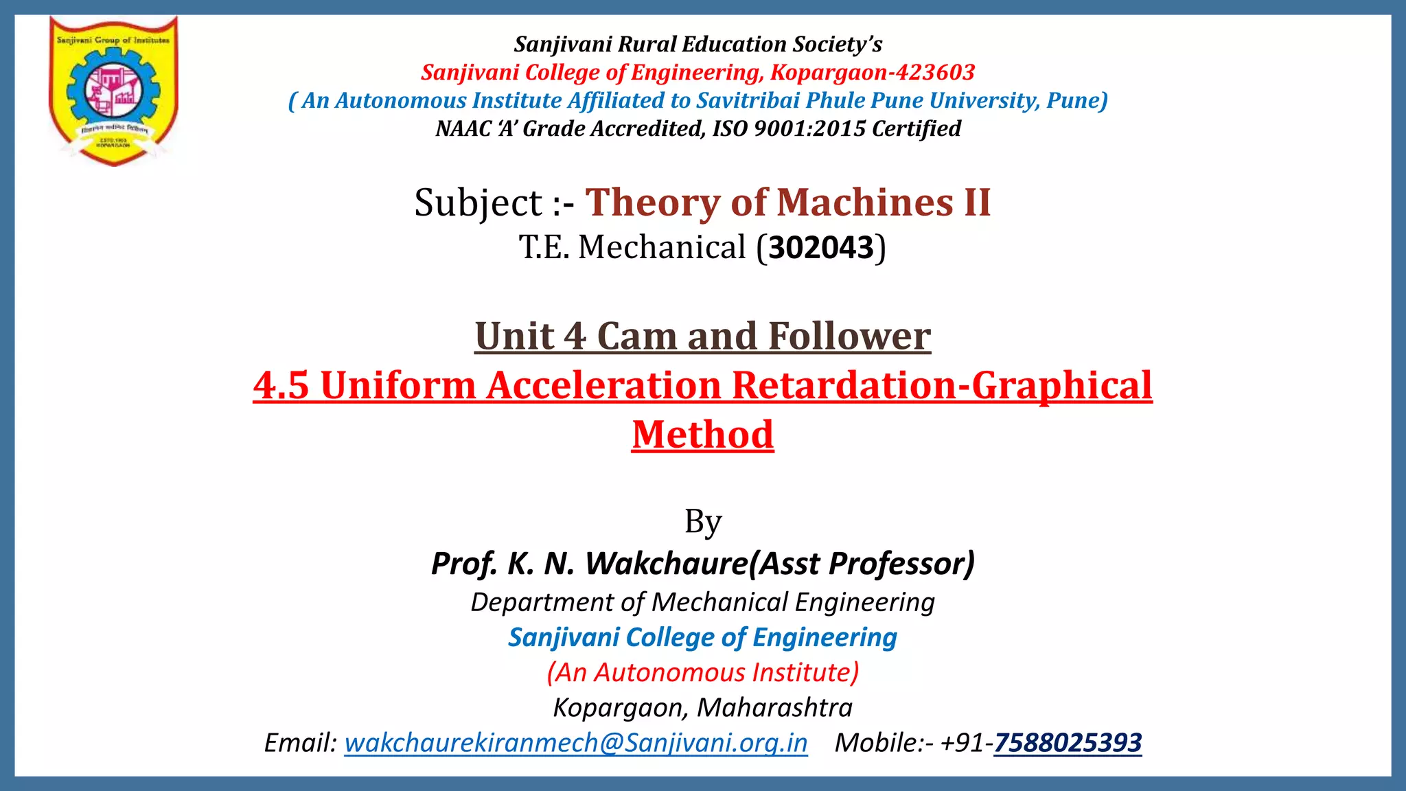
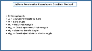
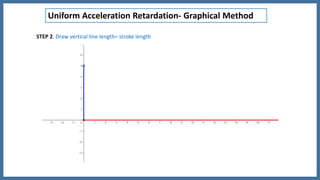

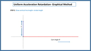

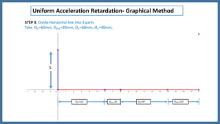
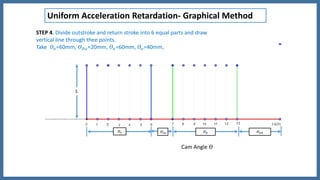

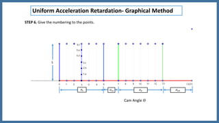
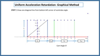
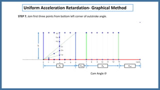
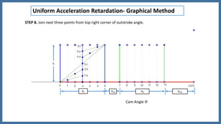
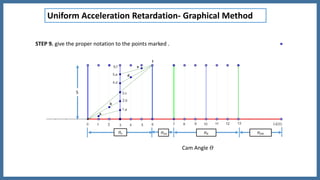
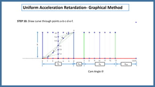
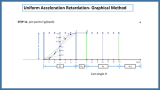
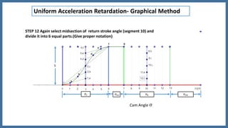
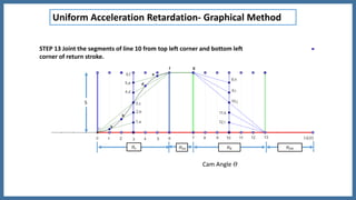
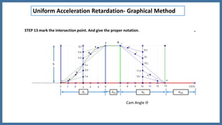
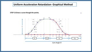


This document provides steps for graphically determining uniform acceleration and retardation of a cam and follower mechanism. It involves: 1. Drawing a horizontal line representing the cam angle and a vertical line for the follower stroke. 2. Dividing the horizontal line into sections for the outstroke, dwell after outstroke, return stroke, and dwell after return stroke. 3. Dividing the outstroke and return stroke sections into equal parts and drawing lines to determine the follower motion. 4. Joining points with diagonal and curved lines to obtain the acceleration and retardation profile of the follower throughout the cam rotation.


