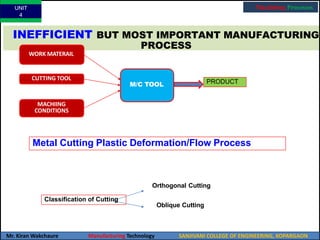
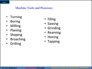
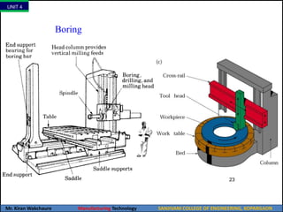
SlideShare a Scribd company logo
1 of 108
Manufacturing
Technology
UNIT
4
UNIT
1
Mr. Kiran
Wakchaure
Manufacturing Technology SANJIVANI COLLEGE OF ENGINEERING, KOPARGAON
Manufacturing Technology
Course
Outcome
Statements Bloom’s Taxonomy
CO1 Classify and compare different materials based on their properties to
select appropriate materials for specific manufacturing applications.
2 Understand
CO2 Design and optimize casting processes for the manufacturing of high-
quality components using knowledge of materials, process parameters,
and quality control techniques.
3 Apply
CO3 Select and optimize metal forming processes for specific applications using
knowledge of process parameters, material properties, and tool design.
3 Analyse
CO4 Analyze and optimize metal cutting processes for efficiency, quality, and
cost-effectiveness using knowledge of cutting tools, machine tools, and
cutting parameters.
3 Apply
CO5 Select and optimize joining processes for specific applications using
knowledge of materials, joint design, and welding parameters.
3 Apply
CO6 Evaluate and select appropriate advanced manufacturing processes for
specific applications using knowledge of process capabilities, limitations,
and economic feasibility.
3 Evaluate
Manufacturing technology refers to the tools, techniques, and processes used in the
production of goods, including the design, development, and manufacturing of products.
It involves the application of various technologies, such as engineering, materials
science, computer science, and management science, to create products in an efficient,
effective, and cost-effective manner.
The goal of manufacturing technology is to produce products that meet the customer's
requirements and expectations while maximizing efficiency, productivity, and
profitability.
UNIT
4
Mr. Kiran Wakchaure Manufacturing Technology SANJIVANI COLLEGE OF ENGINEERING, KOPARGAON
Manufacturing Technology
UNIT 4
Mr. Kiran Wakchaure Manufacturing Technology SANJIVANI COLLEGE OF ENGINEERING, KOPARGAON
INEFFICIENT BUT MOST IMPORTANT MANUFACTURING
PROCESS
MACHIING
CONDITIONS
M/C TOOL PRODUCT
WORK MATERAIL
CUTTING TOOL
Metal Cutting Plastic Deformation/Flow Process
Orthogonal Cutting
Oblique Cutting
Classification of Cutting
UNIT
4
Mr. Kiran Wakchaure Manufacturing Technology SANJIVANI COLLEGE OF ENGINEERING, KOPARGAON
Machining Processes
MATERIAL REMOVAL PROCESSES
MRPs
Traditional Advanced
Cutting Finishing
Circular
Shape
Other/Prismatic
Shape
Bonded
Abrasive
Loose
Abrasive
• Turning
• Drilling
• Boring
• Milling
• Planning
• Shaping
• Gear Cutting
• Broaching
• Grinding
• Honing
•Coated
Abrasive
• Lapping
• Polishing
Metal Cutting: Relative Motion between workpiece & cutting edge of tool
Cutting Tools: 1. Single Point tool
2. Multiple Point tool
UNIT
4
Mr. Kiran Wakchaure Manufacturing Technology SANJIVANI COLLEGE OF ENGINEERING, KOPARGAON
NATURE OF RELATIVE MOTION BETWEEN
THE TOOL AND WORKPIECE
UNIT
4
Mr. Kiran Wakchaure Manufacturing Technology SANJIVANI COLLEGE OF ENGINEERING, KOPARGAON
Machining Processes
OPERATION MOTION OF
JOB
MOTION OF
CUTTING
TOOL
FIGURE OF
OPEARTION
TURNING ROTARY TRANSLATORY
(FORWARD)
BORING ROTATION TRANSLATION
(FORWARD)
DRILLING FIXED (NO
MOTION)
ROTATION AS
WELL AS
TRANSLATOR
Y FEED
UNIT
4
Mr. Kiran Wakchaure Manufacturing Technology SANJIVANI COLLEGE OF ENGINEERING, KOPARGAON
Machining Processes
PLANING TRANSLATORY INTERMITTENT
TRANSLATION
MILLING TRANSLATORY ROTATION
GRINDING ROTARY /
TRANSLATORY
ROTARY
WHAT IS THE BASIC DIFFERENCE BETWEEN ?
TURNING
BORING
PLANING
DRILLING
MILLING
GRINDING
• SINGLE VS MULTI POINT
•CONTINUOUS AND
INTERMITTENT
AND
Fundamentals of Cutting
Examples of cutting processes.
Figure: Basic principle of the turning operations.
Figure: Two-dimensional cutting
process, also called orthogonal
cutting. Note that the tool shape
and its angles, depth of cut, to, and
the cutting speed, V, are all
independent variables.
UNIT
4
Mr. Kiran Wakchaure Manufacturing Technology SANJIVANI COLLEGE OF ENGINEERING, KOPARGAON
Machining Processes
Types of Cutting
o Orthogonal Cutting (2-D Cutting):
Cutting edge is (1) straight, (2)parallel to the original plane surface on the
work piece and (3)perpendicular to the direction of cutting. For example:
Operations: Lathe cut-off operation, Straight milling, etc.
o Oblique Cutting (3-D Cutting):
Cutting edge of the tool is inclined to the line normal to the cutting
direction. In actual machining, Turning, Milling etc. / cutting operations are
oblique cutting(3-D)
ORTHOGONAL CUTTING
OBLIQUE CUTTING
UNIT
4
Mr. Kiran Wakchaure Manufacturing Technology SANJIVANI COLLEGE OF ENGINEERING, KOPARGAON
Machining Processes
Factors Influencing Cutting Process
PARAMETER INFLUENCE AND INTERRELATIONSHIP
CUTTING SPEED,
DEPTH OF CUT, FEED,
CUTTING FLUIDS
FORCES, POWER, TEMPERATURE RISE, TOOL LIFE,
TYPE OF CHIP
, SURFACE FINISH.
TOOL ANGLES
CONTINUOUS CHIP
BUILT-UP EDGE CHIP
AS ABOVE, INFLUENCE ON CHIP FLOW DIRECTION,
RESISTANCE TO TOOL CHIPPING.
GOOD SURFACE FINISH; STEADY CUTTING FORCES;
UNDESIRABLE IN AUTOMATED MACHINERY.
POOR SURFACE FINISH, THIN STABLE EDGE CAN
PROTECT TOOL SURFACES.
DISCONTINUOUS
CHIP
DESIRABLE FOR EASE OF CHIP DISPOSAL;
FLUCTUATING CUTTING FORCES; CAN AFFECT
TEMPERATURE RISE
SURFACE FINISH AND CAUSE VIBRATION AND
CHATTER.
INFLUENCES TOOL LIFE, PARTICULARLY CRATER
WEAR, AND DIMENSIONAL ACCURACY OF
WORKPIECE; MAY CAUSE THERMAL DAMAGE TO
TOOL WEAR DIMENSIONAL
FORCES AND
WORKPIECE SURFACE.
INFLUENCES SURFACE FINISH,
ACCURACY
, TEMPERATURE RISE,
POWER.
TOOL WEAR
MACHINABILITY
RELATED TO TOOL LIFE, SURFACE FINISH, FORCES
AND POWER
UNIT 4
Mr. Kiran Wakchaure Manufacturing Technology SANJIVANI COLLEGE OF ENGINEERING, KOPARGAON
13
Machining = Chip formation by a tool
UNIT 4
Mr. Kiran Wakchaure Manufacturing Technology SANJIVANI COLLEGE OF ENGINEERING, KOPARGAON
14
Big lathe with big chips
UNIT 4
Mr. Kiran Wakchaure Manufacturing Technology SANJIVANI COLLEGE OF ENGINEERING, KOPARGAON
15
Discontinuous chips
UNIT 4
Mr. Kiran Wakchaure Manufacturing Technology SANJIVANI COLLEGE OF ENGINEERING, KOPARGAON
16
Continuous chips
UNIT 4
Mr. Kiran Wakchaure Manufacturing Technology SANJIVANI COLLEGE OF ENGINEERING, KOPARGAON
Machine Tools and Processes
• Turning
• Boring
• Milling
• Planing
• Shaping
• Broaching
• Drilling
• Filing
• Sawing
• Grinding
• Reaming
• Honing
• Tapping
UNIT 4
Mr. Kiran Wakchaure Manufacturing Technology SANJIVANI COLLEGE OF ENGINEERING, KOPARGAON
Classification of Conventional Machining
• Cutting processes
– Single point: e.g. shaping, planing, turning, boring, etc.
– Multiple point: e.g. milling, drilling, etc.
• Abrasive processes
– Grinding, honing, etc.
UNIT 4
Mr. Kiran Wakchaure Manufacturing Technology SANJIVANI COLLEGE OF ENGINEERING, KOPARGAON
19
Lathe (for turning)
UNIT 4
Mr. Kiran Wakchaure Manufacturing Technology SANJIVANI COLLEGE OF ENGINEERING, KOPARGAON
20
Lathe Parts
UNIT 4
Mr. Kiran Wakchaure Manufacturing Technology SANJIVANI COLLEGE OF ENGINEERING, KOPARGAON
21
Typical Insert Cutting Tool
insert
holder
UNIT 4
Mr. Kiran Wakchaure Manufacturing Technology SANJIVANI COLLEGE OF ENGINEERING, KOPARGAON
22
UNIT 4
Mr. Kiran Wakchaure Manufacturing Technology SANJIVANI COLLEGE OF ENGINEERING, KOPARGAON
23
Boring
UNIT 4
Mr. Kiran Wakchaure Manufacturing Technology SANJIVANI COLLEGE OF ENGINEERING, KOPARGAON
Old Boring Machine
UNIT 4
Mr. Kiran Wakchaure Manufacturing Technology SANJIVANI COLLEGE OF ENGINEERING, KOPARGAON
25
Shaper
UNIT 4
Mr. Kiran Wakchaure Manufacturing Technology SANJIVANI COLLEGE OF ENGINEERING, KOPARGAON
Trepanning
UNIT 4
Mr. Kiran Wakchaure Manufacturing Technology SANJIVANI COLLEGE OF ENGINEERING, KOPARGAON
27
Drilling
(a)
UNIT 4
Mr. Kiran Wakchaure Manufacturing Technology SANJIVANI COLLEGE OF ENGINEERING, KOPARGAON
28
Milling
UNIT 4
Mr. Kiran Wakchaure Manufacturing Technology SANJIVANI COLLEGE OF ENGINEERING, KOPARGAON
29
Face Milling
UNIT 4
Mr. Kiran Wakchaure Manufacturing Technology SANJIVANI COLLEGE OF ENGINEERING, KOPARGAON
30
Horizontal Mill
31
Old Horizontal Mill
32
Vertical Mill
33
Milling Types
34
Broach
Reamers
bridge reamer
36
Honing
Thread Tap and Die
internal external
Shaping
Planing
Mechanics of Chip Formation
(a) Basic mechanism of chip formation in metal cutting. (b)
Velocity diagram in the cutting zone.
V=> Cutting velocity, Vs= Shear velocity, Vc=Chip velocity
Φ= Shear angle, α=Rake angle
Theory of Metal Cutting
• Metal cutting or Machining is the process of producing
workpiece by removing unwanted material from a block
of metal, in the form of chips.
• This process is most important since almost all the
products get their final shape and size by metal removal,
either directly or indirectly.
• The major drawback of the process is loss of material in
the form of chips.
THE MECHANICS OF CHIP FORMATION
• A wedge shaped tool is made to move relative to the
workpiece. As the tool makes contact with the metal
exerts a pressure on it resulting in the compression of the
metal near the tool tip.
• This induces shear-type deformation within the metal and
it starts moving upward along the top face of the tool. As
the tool advances, the material ahead of it is sheared
continuously along a plane called the Shear plane.
• This shear plane is actually a narrow zone (of the order of
about 0.025 mm) and extends from the cutting edge of
the tool to the surface of the workpiece.
Theory of Metal Cutting
• The cutting edge of the tool is formed by two intersecting
surfaces. The surface along which the chip moves upwards
is called “Rake surface” and the other surface which is
relieved to avoid rubbing with the machined surface, is
called “Flank”.
• The angle between the rake surface and the normal is
known as “Rake angle” (which may be positive or negative),
and the angle between the flank and the horizontal
machined surface is known as the “relief or clearance
angle”. Most cutting processes have the same basic features
as in Fig. , where a single point cutting tool is used (a milling
cutter, a drill, and a broach can be regarded as several
single-point tools joined together and are known as multi-
point tools)
MECHANICS OF CHIP FORMATION
 Plastic deformation along shear plane
(Merchant)
 The fig. where the work piece remains
stationary and the tool advances in to the work
piece towards left.
 Thus the metal gets compressed very severely,
causing shear stress.
 This stress is maximum along the plane is
called shear plane.
 If the material of the workpiece is ductile, the
material flows plastically along the shear plane,
forming chip, which flows upwards along the
face of the tool.
 The tool will cut or shear off the metal, provided
by;
•The tool is harder than the work metal
•The tool is properly shaped so that its
edge can be effective in cutting the
metal.
•Provided there is movement of tool
relative to the material or vice versa, so
as to make cutting action possible.
Fig: Shear Plane
Primary shear
zone (PSDZ)
Secondary shear
deformation zone
(SSDZ)
Fig: Shear deformation
zones
Fig: Shaping
operation
Fig: Shear deformation
zones
tc tc
sin
sin
ABC & ABD
tu
AB 
also, AB  
sin(90  ( )) cos( )
tu

tc cos( )
tc :Chip thickness
tu :Uncut chip thickness
Vf :Chip Sliding Velocity
Vs : Shear Velocity
Vc :Cutting Velocity
 : Shear Angle
Fig: Schematic of Geometry of chip formation
Geometry of chip Formation:
φ
90-ф+α = 90-(ф-α)
(= feed) and α are already
How to determine φ & rc ?
tc should be determined from the chip. tu
known.
c
c
t
rc sin
r 
tu
:Chip thickness Ratio /Coeffinicient
1

coscos  sinsin
1 rccotcos  rcsin
rccos  (1 rc sin) tan
cos 
 tan 
 rc
1 r sin 
 c 
φ
90-ф+α
= 90-(ф-α)
Substitute the value of tu /tc
from earlier slide and simplify to get:
SHEARANGLEAND CHIPTHICKNESS RATIO EV
ALUATION
To determine tc with micrometer, is difficult and not so because of
uneven surface. How? (say, f=0.2 mm/rev. An error of even 0.05 mm will cause
an error of 25 % in the measurement of tc)
Volume Constancy ConditionDr
.:V
.VK.joailnu,I
I
m
TK
ea
n
p
ou
fr Uncut chip = Volume of cut chi3p
Lutub  Lctcb
Lctc  Lutu
c
c u
t L
or,r 
tu 
Lc
Lc = Chip length
Lu = Uncut chip length
b = Chip width
(2-D Cutting)
SHEARANGLEAND CHIPTHICKNESS RATIO EV
ALUATION
LENGTHOF THE CHIP MAY BE MANY CENTIMETERS HENCE THE ERROR IN
EVALUTION OF rc WILLBEC OMPARATIVELYMUCH LOWER.
(rc = Lc / Lu)
4
Force Analysis
Clearance Angle
Work
Tool
Chip
Ft
Fc
F
N
Fs
α
α
β
∅
Fn
R
79
α
G
E
A
B
∅
D
F
α
Δ FAD = (β - α)
Δ GAD = φ + (β - α)
FORCE CIRCLE DIAGRAM
Forces in Orthogonal Cutting:
•Frictionforce,F
•ForcenormaltoFrictionforce,N
•CuttingForce, FC
•Thrustforce,Ft
• ShearForce, FS
•ForceNormal toshearforce, Fn
•Resultantforce,R
Force Analysis
F  Ft cos  Fc sin
N  Fc cos  Ft sin
Coefficient of Friction ()
cos  Fc sin
  tan  
F

Ft
N Fc cos  Ft sin
  Friction Angle
 
Ft
 Fc tan
Fc  Ft tan
also,   tan1
()
FORCEANAL
YSIS
Dr
. V
.K.jain, IIT Kanpur
DIVIDE R.H.S. BY Cos α
FN  Ft cos  Fc sin
also,
FC  R cos( )
FS  R cos(   )

FC

cos( )
FS cos(   )
S
ShearPlaneArea (A ) 
tub 
 b

tu
sin  sin 
 
Foce Analysis
FS  Fc cos  Ft sin
Δ FAD = (β - α)
Δ GAD = φ + (β - α)
Let  be the strength of work material
t b

u
sin
FS  AS 
C
F 
 tub  cos( ) 
 sin  cos(   ) 
  
and, 1 
R 
 tub 


 sin   cos(   ) 
   
u
t
t b
sin
F  R sin( )  
sin( )
cos(   )
Ft
Fc
 tan( )
Foce Analysis
chip
S
A
) 
FS
Mean Shear Stress (t
(On Chip)

(Fc cos  Ft sin)sin
b tu
chip
S
A
) 
FN
Mean Normal Stress (
(On Chip)
=
(Ft cos  Fc sin)sin
b tu
Foce Analysis
VELOCITY ANALYSIS
Vc :Cutting velocity of tool relative to workpiece
Vf :Chip flow velocity
Vs : Shear velocity
Using sine Rule:
Vc

Vf

Vs
sin(90( )) sin sin(90)
Vc Vs

Vf

cos( ) sin cos
f c c
and V  V r
Vc sin
cos( )
s
c
V 
Vc cos 
Vs

cos
cos( ) V cos( )
11
Shear Strain & Strain Rate
Two approaches of analysis:
Thin Plane Model:- Merchant, PiisPanen, Kobayashi & Thomson
Thick Deformation Region:- Palmer, (At very low speeds) Oxley, kushina,
Hitoni
Thin Zone Model: Merchant
ASSUMPTIONS:-
• Tool tip is sharp, No Rubbing, No Ploughing
• 2-D deformation.
• Stress on shear plane is uniformly distributed.
• Resultant force R on chip applied at shear plane is equal, opposite and
collinear to force R’ applied to the chip at tool-chip interface. 12
Expression for Shear Strain
The deformation can be idealized as a process of block slip (or preferred
slip planes)
Length
ShearStrain() 
deformation
 
s

AB

AD

DB
y CD CD CD
 tan( )  cot
sin( )sin  cos cos( )
,
sin cos( )
 
cos
sin cos( )
Dr
. V
.K.jain, IIT Kanpur
Shear angle relationship
• Helpful to predict position of shear plane (angle φ)
• Relationship between-
Shear Plane Angle (φ)
Rake Angle (α)
Friction Angle(β)
Several Theories
Earnst-Merchant(Minimum Energy Criterion):
Shear plane is located where least energy is required for shear.
Assumptions:-
• Orthogonal Cutting.
• Shear strength of Metal along shear plane is not affected by
Normal stress.
• Continuous chip without BUE.
• Neglect energy of chip separation. Dr
. V
.K.jain, IIT Kanpur 15
Condition for minimum energy,
dFc
d
 0
u
dFc
d
 t b cos ( )
cos cos(   ) sin sin(   )
 
sin2
 cos2
(   )
 
 0
cos cos(   ) sinsin(   )  0
cos(2   )  0
2
2    

 
 
1
( )
4 2
Shear angle relationship
Assuming No Strain hardening:
Dr
. V
.K.jain, IIT Kanpur 60
Tool Nomenclature/Angles
Side Cutting Edge Angle (SCEA).
• Side cutting edge angle, Cs, also known as lead angle, is the angle
between the side cutting edge and the side of the tool shank.
• It is the angle which prevents interference as the tool enters the work
materials.
• The tip of the tool is protected at the start of the cut, Fig. , as it enables
the tool to contact the work first behind the tip.
• Satisfactory values of SCEA vary from 15° to 30°, for general machining
Tool Nomenclature/Angles
End Cutting Edge Angle (ECEA).
• This is the angle between the end cutting edge and a line normal to the
tool shank.
• Ce. The ECEA provides a clearance or relief to the trailing end of the
cutting edge to prevent rubbing or drag between the machined surface
and the trailing (non-cutting) part of the cutting edge
• An angle of 8° to 15° has been found satisfactory in most cases on side
cutting tools
Tool Nomenclature/Angles
Side Relief Angle (SRA).
It is the angle between the portion of the side flank immediately below the
side cutting edge and a line perpendicular to the base of the tool, and
measured at right angle to the side flank.
These angles (denoted 𝜃𝑠 ) are provided so that the flank of the tool clears
the workpiece surface and there is no rubbing action between the two.
Relief angles range from 5° to 15° for general turning
Tool Nomenclature/Angles
End Relief Angle (ERA).
It is the angle between the portion of the end flank immediately below
the end cutting edge and a line perpendicular to the base of the tool, and
measured at right angle to the end flank.
These angles (denoted 𝜃𝑒 ) are provided so that the flank of the tool clears
the workpiece surface and there is no rubbing action between the two.
Relief angles range from 5° to 15° for general turning
Tool Nomenclature/Angles
Back-Rake Angle (BRA).
It is the angle between the face of the tool and a line parallel to the base
of the tool and measured in a plane (perpendicular) through the side
cutting edge.
The top face of the tool over which the chip flows is known as the rake
face. The angle which this face makes with the normal to the machined
surface at the cutting edge is known as “Back-rake angle, 𝛼𝑏 ”,
Tool Nomenclature/Angles
Side -Rake Angle (SRA).
The angle between the face and a plane parallel to the tool base and
measured in a plane perpendicular to both the base of the tool holder and
the side cutting edge, is known as “Side-rake angle, 𝛼𝑠 ”. The rake angles may
be positive, zero, or negative.
Cutting angle and the angle of shear are affected by the values for rake
angles. Larger the rake angle, smaller the cutting angle (and larger the shear
angle) and the lower the cutting force and power. However, since increasing
the rake angle decreases the cutting angle, this leaves less metal at the point
of the tool to support the cutting edge and conduct away the heat
Tool Nomenclature/Angles
Side-Rake Angle (SRA). It is the angle between the tool face and a line
parallel to the base of the tool and measured in a plane perpendicular to
the base and the side cutting edge
Larger the rake angle, smaller the cutting angle (and larger the shear
angle) and the lower the cutting force and power. However, since
increasing the rake angle decreases the cutting angle, this leaves less metal
at the point of the tool to support the cutting edge and conduct away the
heat.
Tool Nomenclature/Angles
Nose Radius.
Nose radius is favourable to long tool life and good surface finish. A sharp
point on the end of a tool is highly stressed, short lived and leaves a
groove in the path of cut. There is an improvement in surface finish and
permissible cutting speed as nose radius is increased from zero value.
Too large a nose radius will induce chatter. The use of following values for
nose radius is recommended :
R = 0.4 mm, for delicate components. 1.5 mm for heavy depths of cut,
interrupted cuts and heavy feeds. = 0.4 mm to 1.2 mm for disposable
carbide inserts for common use. = 1.2 to 1.6 mm for heavy duty inserts.
Tool Nomenclature/Angles
American Standards Association System (ASA) or American National Standards Institute (ANSI).
Tool Nomenclature/Angles
(a)
(c)
(b)
Fig: Turning Operations
UNIT 4
Mr. Kiran Wakchaure Manufacturing Technology SANJIVANI COLLEGE OF ENGINEERING, KOPARGAON
Right-Hand Cutting Tool
Figure 20.10 (a) Schematic illustration of a right-hand cutting tool.
Although these tools have traditionally been produced from solid tool-
steel bars, they have been largely replaced by carbide or other
inserts of various shapes and sizes, as shown in (b). The various
angles on these tools and their effects on machining are described in
Section 22.3.1.
UNIT 4
Mr. Kiran Wakchaure Manufacturing Technology SANJIVANI COLLEGE OF ENGINEERING, KOPARGAON
Types of Chips
 Continues Chips
 Discontinues Chips
 Continuous Chips
with Built up Edge (BUE)
Conditions for Continuous
Chips:
• Sharp cutting edges
• Low feed rate (f)
• Large rake angle ()
• Ductile work material
• High cutting speed (v=)
• Low friction at Chip-Tool interface
CHIP FORMATION
Fig; Schematic of chip
formation
Fig; Schematic of different types of chip
UNIT 4
Mr. Kiran Wakchaure Manufacturing Technology SANJIVANI COLLEGE OF ENGINEERING, KOPARGAON
Types of Chips
(a) Continuous chip
with narrow,
straight primary
shearzone;
(b) Secondary shear
zone at the chip-
toolinterface;
(c) Continuous chip
withbuilt-upedge
(d) Continuous chip
with large primary
shearzone
(e) Segmented
or
nonhomogeneous
chipand
(f) Discontinuous
chip.
(f)
(b)
(a) (c)
(d) (e)
Source:After M.C.Shaw,P
.K.Wright,andS.Kalpakjian.
UNIT 4
Mr. Kiran Wakchaure Manufacturing Technology SANJIVANI COLLEGE OF ENGINEERING, KOPARGAON
Built-Up Edge Chips
(b)
(c)
(a)
Built-up edge (BUE) is a common type of chip formation that occurs during metal cutting processes. It is a
localized accumulation of material on the cutting tool edge that is formed due to the high temperatures and
pressures generated during cutting.
BUE is typically observed in machining operations that involve ductile materials such as aluminum and
copper, and it can also occur in steel cutting under certain conditions. The formation of BUE can result in a
number of issues such as increased cutting forces, tool wear, surface finish problems, and reduced
accuracy of the machined part.
To prevent or minimize BUE formation, various strategies can be employed such as reducing cutting
speeds and feeds, optimizing cutting tool geometry and material selection, using lubricants or coolants,
and ensuring proper machine setup and maintenance.
TURNING LAY
MILLING LAY
UNIT 4
Mr. Kiran Wakchaure Manufacturing Technology SANJIVANI COLLEGE OF ENGINEERING, KOPARGAON
Continuous chip Results in:
• Good surface finish
• High tool life
• Low power consumptions
Discontinuous Chip:
Chip in the form of discontinuous segments:
 Easy disposal
 Good surface finish
Conditions for discontinuous chips:
• Brittle Material
• Low cutting speed
• Small rake angle
Built up Edge:
Conditions for discontinuous chips:
High friction between Tool & chip
Ductile material
Particles of chip adhere to the rake face of the tool near cutting edge
UNIT 4
Mr. Kiran Wakchaure Manufacturing Technology SANJIVANI COLLEGE OF ENGINEERING, KOPARGAON
Chip- Breaking
• The chip breaker break the produced chips into small pieces.
• The work hardening of the chip makes the work of the chip breakers
easy.
• When a strict chip control is desired, some sort of chip breaker has to be
employed.
• The following types of chip breakers are commonly used:
a)
b)
c)
d)
Groove type
Step type
Secondary Rake type
Clamp type
Fig: Schematics of different types of chip barkers
UNIT 4
Mr. Kiran Wakchaure Manufacturing Technology SANJIVANI COLLEGE OF ENGINEERING, KOPARGAON
Chip Breakers
(a) Schematic illustration of the action of a chip breaker. Note that the chip
breaker decreases the radius of curvature of the chip. (b) Chip breaker
clamped on the rake face of a cutting tool. (c) Grooves in cutting tools
acting as chip breakers.
UNIT 4
Mr. Kiran Wakchaure Manufacturing Technology SANJIVANI COLLEGE OF ENGINEERING, KOPARGAON
Examples of Chips Produced in Turning
Various chips produced in turning: (a) tightly curled chip; (b) chip hits
workpiece and breaks; (c) continuous chip moving away from workpiece;
and (d) chip hits tool shank and breaks off. Source: G. Boothroyd, Fundamentals of Metal
Machining and Machine Tools. Copyright © 1975; McGraw-Hill Publishing Company.
UNIT 4
Mr. Kiran Wakchaure Manufacturing Technology SANJIVANI COLLEGE OF ENGINEERING, KOPARGAON
Types of Cutting
o Orthogonal Cutting (2-D Cutting):
Cutting edge is straight, parallel to the original plane surface at
the work piece and perpendicular to the direction of cutting.
E.g. Operations:
• Lathe cut-off tools
• Straight milling cutters etc.
o Oblique Cutting:
Cutting edge of the tool is inclined to the line normal to the
cutting direction. In actual machining, Turning, Milling etc/ cutting
operations are oblique cutting(3-D
UNIT 4
Mr. Kiran Wakchaure Manufacturing Technology SANJIVANI COLLEGE OF ENGINEERING, KOPARGAON
Forces in Two-Dimensional Cutting
/ Orthogonal Cutting
Forces acting on a cutting tool in two-dimensional cutting.
Note that the resultant force, R, must be collinear to balance the forces.
UNIT 4
Mr. Kiran Wakchaure Manufacturing Technology SANJIVANI COLLEGE OF ENGINEERING, KOPARGAON
Cutting With an Oblique Tool
(a)Schematic illustration of cutting with an oblique tool.
(b)Top view showing the inclination angle, i.
(c)Types of chips produced with different inclination.
UNIT 4
Mr. Kiran Wakchaure Manufacturing Technology SANJIVANI COLLEGE OF ENGINEERING, KOPARGAON
Flank and Crater Wear
(e)
(d)
(a) (b) (c)
(a) Flank and crater wear in a cutting tool. Tool moves to the left.
(b) View of the rake face of a turning tool, showing nose radius R and crater wear
pattern on the rake face of the tool.
(c) View of the flank face of a turning tool, showing the average flank wear land VB
and the depth-of-cut line (wear notch).
(d) Crater and (e) flank wear on a carbide tool. Source: J.C. Keefe, Lehigh University.
UNIT 4
Mr. Kiran Wakchaure Manufacturing Technology SANJIVANI COLLEGE OF ENGINEERING, KOPARGAON
Mechanics of Metal Cutting
UNIT 4
Mr. Kiran Wakchaure Manufacturing Technology SANJIVANI COLLEGE OF ENGINEERING, KOPARGAON
85
Turning -MRR
UNIT 4
Mr. Kiran Wakchaure Manufacturing Technology SANJIVANI COLLEGE OF ENGINEERING, KOPARGAON
86
Turning
Average cutting speed, Vavg = DavgN
Davg is the average diameter of workpiece
N is the spindle speed in rpm
Material removal rate, MRR = Vavgdf
d is the depth of cut
f is the feed (units: mm/rev or in/rev)
Cutting power, Pc = ucMRR=FcV
Fc=Cutting force
V = Cutting speed
Machining time, tm = L/(fN) = L/F
F is the feed rate (units: mm/min or in/min)
v
N1  500RPM
f1  0.15mm / rev
d1  0.3mm
CuttingSpeed , Vc  .R
Vc  1308.9mm / sec
M RR  58.905 mm 3
/ sec
D1
L
Depth of cut
Feed
N1
W/P
Tool
Turning operation
Problem-1:
A turning operation has to be performed on an aluminum rod of diameter50 mm and
length 300mm. The Spindle speed of lathe is given to be 500 RPM. The feed and depth of
cut are 0.15mm/rev and 0.3 mm respectively. Draw a neat sketch of the turning
operation described above. Find out the cutting speed in mm/s and the volumetric
material removal rate (MRRv).
Solution:
M R Rv  Vc  f1  d1
60
c
v
V
N1  500RPM
f1  0.15mm / rev
d1  0.3mm
CuttingSpeed , Vc  .R
  500     50
 
Vc  1308.9mm / sec
M RRv    D1  N1  f1  d1
M RRv  Vc  f1  d1
M RRv  1308.9  0.15  0.3
M RR  58.905 mm 3
/ sec
D1
L
Depth of cut
Feed
N1
W/P
Tool
Turning operation
Problem-1:
A turning operation has to be performed on an aluminum rod of diameter50 mm and
length 300mm. The Spindle speed of lathe is given to be 500 RPM. The feed and depth of
cut are 0.15mm/rev and 0.3 mm respectively. Draw a neat sketch of the turning
operation described above. Find out the cutting speed in mm/s and the volumetric
material removal rate (MRRv).
Solution:
Milling
fr
dr
N
feed
workpiece
cutter
da
Milling Modes
Up Milling Down Milling
dr
91
Milling
Cutting speed, V = DN
D is the cutter diameter
Material removal rate, MRR = fNdadr = Fdadr
da is the axial depth of cut
dr is the radial depth of cut
f is the feed per revolution (= ftNt ; ft is the feed per cutting edge/tooth and Nt is
the number of teeth)
Cutting power, Pc = ucMRR
Machining time, tm = (L + lc)/F
lc is the length of the cutter’s first contact with the workpiece
Problem-2
An aluminum block of length 50 mm and width 70 mm is being milled using a slab milling
cutter with 50 mm diameter. The feed of the table is 15 mm/min. The milling cutter
rotates at 60 RPM in clockwise direction and width of cut is equal to the width of the
workpiece. Draw a neat sketch of the milling operation describing above conditions. The
thickness of the workpiece is 20 mm. If depth of cut of 2 mm is used then find out
cutting speed and volumetric material removal rate (MRRv).
Milling operation
N2
L
D
2
W
Feed
Milling cutter
W/P
t
W
1000
1000
60
c
v
v
V
M illing Cutter Diameter, D2  50mm
Width of cut,WOC  70mm
Depth of cut, d 2  2mm
feed , f2  15mm / min
 DN
Cutting Speed , Vc  2
m / min
  50    60   25
 
Vc  9.424m / min
M RRv  W OC  f2  d 2
M RR  70 
15
 2
MRR  35 mm3
/ sec
Solution:
Problem-2
An aluminum block of length 50 mm and width 70 mm is being milled using a slab milling
cutter with 50 mm diameter. The feed of the table is 15 mm/min. The milling cutter
rotates at 60 RPM in clockwise direction and width of cut is equal to the width of the
workpiece. Draw a neat sketch of the milling operation describing above conditions. The
thickness of the workpiece is 20 mm. If depth of cut of 2 mm is used then find out
cutting speed and volumetric material removal rate (MRRv).
Milling operation
N2
L
D
2
W
Feed
Milling cutter
W/P
t
W
1000
60
v
v
M illing Cutter Diameter, D2  50mm
Width of cut,WOC da  70mm
Depth of cut, d r  2mm
feed , f2  15mm / min
 DN
Cutting Speed , Vc  2
m / min
Vc  9.424m / min
M RRv da  f2  d r
M RR  70 
15
 2
MRR  35 mm3
/ sec
Solution:
Fdadr
Problem-3
Following the milling operation, a through hole is to be drilled on the same workpiece.
Find out the cutting speed and volumetric material removal rate if the drill of diameter 10
mm is being rotated at same RPM as in case of milling cutter with feed rate as 0.5
mm/rev.
W/P
Feed
N3
D
3
Drilling operation
Drill bit
t
3
1000
1000
4
c
v
Diameter of Drill, D  10mm
N3  60RPM
feed , f3  0.5mm / rev
Cutting Speed , V 
 N 3 D3
m / min
  60 10 
Vc   

m / min
Vc  1.884m / min  31.4mm / sec
  D 2
MRRv  3
 f3  N3
4
 102
MRRv   0.5  60
MRR  2356.19 mm3
/ min  39.27mm3
/ sec
Solution:
Tool Life
Examples of Wear and Tool Failures
Figure 20.18
illustrations of
(a) Schematic
types of wear
observed on various types of cutting
tools. (b) Schematic illustrations of
catastrophic tool failures. A study
of the types and mechanisms of tool
wear and failure is essential to the
development of better tool
materials.
Range of n Values for Eq. (20.20) for Various
Tool Materials
High-speed
steels Cast alloys
Carbides
Ceramics
0.08–0.2
0.1–0.15
0.2–0.5
0.5–0.7
Tool Life
Tool-life curves for a
variety of
materials.
inverse of
cutting-tool
The negative
the slope of
these curves is the
exponent n in the Taylor
tool-life equations and C
is the cutting speed at T
= 1 min.
Thank You….

More Related Content

Similar to Manufacturing Processes- Machining Processes

unit 1 theory-of-metal-cutting (1).pptx
unit 1 theory-of-metal-cutting (1).pptxunit 1 theory-of-metal-cutting (1).pptx
unit 1 theory-of-metal-cutting (1).pptxdscemahesh
 
The only way to shape hardened or brittle material Economics (for small part ...
The only way to shape hardened or brittle material Economics (for small part ...The only way to shape hardened or brittle material Economics (for small part ...
The only way to shape hardened or brittle material Economics (for small part ...AlamSutra
 
Aragaw manufacturing engineering ii lecture note-chapter-i
Aragaw manufacturing engineering ii lecture note-chapter-iAragaw manufacturing engineering ii lecture note-chapter-i
Aragaw manufacturing engineering ii lecture note-chapter-iAragaw Gebremedhin
 
Unit 1 Theory of metal Cutting
Unit 1  Theory of metal CuttingUnit 1  Theory of metal Cutting
Unit 1 Theory of metal Cuttingsubrabest
 
Manufacturing Technology- ii Unit 4
Manufacturing Technology- ii Unit 4Manufacturing Technology- ii Unit 4
Manufacturing Technology- ii Unit 4Ravi Sankar
 
Theory of metal cutting
Theory of metal cutting Theory of metal cutting
Theory of metal cutting Daniel raj
 
In metal turning, effect of tool rake angles and lubricants on cutting tool l...
In metal turning, effect of tool rake angles and lubricants on cutting tool l...In metal turning, effect of tool rake angles and lubricants on cutting tool l...
In metal turning, effect of tool rake angles and lubricants on cutting tool l...IRJET Journal
 
Optimization of cutting tool material in lathe machine by T-test
Optimization of cutting tool material in lathe machine by T-testOptimization of cutting tool material in lathe machine by T-test
Optimization of cutting tool material in lathe machine by T-testIJMER
 
IRJET- Ballizing – The Latest Technology in Hole Finishing
IRJET-  	  Ballizing – The Latest Technology in Hole FinishingIRJET-  	  Ballizing – The Latest Technology in Hole Finishing
IRJET- Ballizing – The Latest Technology in Hole FinishingIRJET Journal
 
ANALYSIS OF TOOL WEAR IN TURNING OPERATION OF ALUMINIUM
ANALYSIS OF TOOL WEAR IN TURNING OPERATION OF ALUMINIUMANALYSIS OF TOOL WEAR IN TURNING OPERATION OF ALUMINIUM
ANALYSIS OF TOOL WEAR IN TURNING OPERATION OF ALUMINIUMIRJET Journal
 
Factors affecting tool life in machining processes
Factors affecting tool life in machining processesFactors affecting tool life in machining processes
Factors affecting tool life in machining processesmohdalaamri
 
MANUFACTURING SCIENCE II ppt on.pptx
MANUFACTURING SCIENCE II ppt on.pptxMANUFACTURING SCIENCE II ppt on.pptx
MANUFACTURING SCIENCE II ppt on.pptxArvindTiwari790920
 
Experimental Investigation of Effect of Tool Length on Surface Roughness duri...
Experimental Investigation of Effect of Tool Length on Surface Roughness duri...Experimental Investigation of Effect of Tool Length on Surface Roughness duri...
Experimental Investigation of Effect of Tool Length on Surface Roughness duri...IOSR Journals
 
Investigations on Milling Tool: - A Literature Review
Investigations on Milling Tool: - A Literature ReviewInvestigations on Milling Tool: - A Literature Review
Investigations on Milling Tool: - A Literature ReviewIJRES Journal
 

Similar to Manufacturing Processes- Machining Processes (20)

unit 1 theory-of-metal-cutting (1).pptx
unit 1 theory-of-metal-cutting (1).pptxunit 1 theory-of-metal-cutting (1).pptx
unit 1 theory-of-metal-cutting (1).pptx
 
The only way to shape hardened or brittle material Economics (for small part ...
The only way to shape hardened or brittle material Economics (for small part ...The only way to shape hardened or brittle material Economics (for small part ...
The only way to shape hardened or brittle material Economics (for small part ...
 
Mtii
MtiiMtii
Mtii
 
Aragaw manufacturing engineering ii lecture note-chapter-i
Aragaw manufacturing engineering ii lecture note-chapter-iAragaw manufacturing engineering ii lecture note-chapter-i
Aragaw manufacturing engineering ii lecture note-chapter-i
 
work.pptx
work.pptxwork.pptx
work.pptx
 
Unit 1 Theory of metal Cutting
Unit 1  Theory of metal CuttingUnit 1  Theory of metal Cutting
Unit 1 Theory of metal Cutting
 
New TMC.pdf ..
New TMC.pdf                           ..New TMC.pdf                           ..
New TMC.pdf ..
 
Module. 01.pptx
Module. 01.pptxModule. 01.pptx
Module. 01.pptx
 
Manufacturing Technology- ii Unit 4
Manufacturing Technology- ii Unit 4Manufacturing Technology- ii Unit 4
Manufacturing Technology- ii Unit 4
 
Theory of metal cutting
Theory of metal cutting Theory of metal cutting
Theory of metal cutting
 
In metal turning, effect of tool rake angles and lubricants on cutting tool l...
In metal turning, effect of tool rake angles and lubricants on cutting tool l...In metal turning, effect of tool rake angles and lubricants on cutting tool l...
In metal turning, effect of tool rake angles and lubricants on cutting tool l...
 
Optimization of cutting tool material in lathe machine by T-test
Optimization of cutting tool material in lathe machine by T-testOptimization of cutting tool material in lathe machine by T-test
Optimization of cutting tool material in lathe machine by T-test
 
IRJET- Ballizing – The Latest Technology in Hole Finishing
IRJET-  	  Ballizing – The Latest Technology in Hole FinishingIRJET-  	  Ballizing – The Latest Technology in Hole Finishing
IRJET- Ballizing – The Latest Technology in Hole Finishing
 
EFFECT OF MACHINING PARAMETERS ON TOOL LIFE
EFFECT OF MACHINING PARAMETERS ON TOOL LIFEEFFECT OF MACHINING PARAMETERS ON TOOL LIFE
EFFECT OF MACHINING PARAMETERS ON TOOL LIFE
 
ANALYSIS OF TOOL WEAR IN TURNING OPERATION OF ALUMINIUM
ANALYSIS OF TOOL WEAR IN TURNING OPERATION OF ALUMINIUMANALYSIS OF TOOL WEAR IN TURNING OPERATION OF ALUMINIUM
ANALYSIS OF TOOL WEAR IN TURNING OPERATION OF ALUMINIUM
 
Manufacturing Processes
Manufacturing ProcessesManufacturing Processes
Manufacturing Processes
 
Factors affecting tool life in machining processes
Factors affecting tool life in machining processesFactors affecting tool life in machining processes
Factors affecting tool life in machining processes
 
MANUFACTURING SCIENCE II ppt on.pptx
MANUFACTURING SCIENCE II ppt on.pptxMANUFACTURING SCIENCE II ppt on.pptx
MANUFACTURING SCIENCE II ppt on.pptx
 
Experimental Investigation of Effect of Tool Length on Surface Roughness duri...
Experimental Investigation of Effect of Tool Length on Surface Roughness duri...Experimental Investigation of Effect of Tool Length on Surface Roughness duri...
Experimental Investigation of Effect of Tool Length on Surface Roughness duri...
 
Investigations on Milling Tool: - A Literature Review
Investigations on Milling Tool: - A Literature ReviewInvestigations on Milling Tool: - A Literature Review
Investigations on Milling Tool: - A Literature Review
 

More from Kiran Wakchaure

POST PROCESSING IN ADDITIVE MANUFACTURING
POST PROCESSING IN ADDITIVE MANUFACTURINGPOST PROCESSING IN ADDITIVE MANUFACTURING
POST PROCESSING IN ADDITIVE MANUFACTURINGKiran Wakchaure
 
Design for Additive Manufacturing - Introduction
Design for Additive Manufacturing - IntroductionDesign for Additive Manufacturing - Introduction
Design for Additive Manufacturing - IntroductionKiran Wakchaure
 
Introduction of Additive Manufacturing 1
Introduction of Additive Manufacturing 1Introduction of Additive Manufacturing 1
Introduction of Additive Manufacturing 1Kiran Wakchaure
 
Manufacturing Properties of the materials
Manufacturing Properties of the materialsManufacturing Properties of the materials
Manufacturing Properties of the materialsKiran Wakchaure
 
metal_welding_processes Undergraduate Program
metal_welding_processes Undergraduate Programmetal_welding_processes Undergraduate Program
metal_welding_processes Undergraduate ProgramKiran Wakchaure
 
Advanced Manufacturing Processes UG Program
Advanced Manufacturing Processes UG ProgramAdvanced Manufacturing Processes UG Program
Advanced Manufacturing Processes UG ProgramKiran Wakchaure
 
6.1 synthsis of the mechanism
6.1 synthsis of the mechanism6.1 synthsis of the mechanism
6.1 synthsis of the mechanismKiran Wakchaure
 
5.4 gyroscope effect in ship
5.4 gyroscope effect in ship5.4 gyroscope effect in ship
5.4 gyroscope effect in shipKiran Wakchaure
 
5.3 gyroscopic effect on aeroplanes
5.3 gyroscopic effect on aeroplanes5.3 gyroscopic effect on aeroplanes
5.3 gyroscopic effect on aeroplanesKiran Wakchaure
 
5.2 gyroscopic effect on bearings
5.2 gyroscopic effect on bearings5.2 gyroscopic effect on bearings
5.2 gyroscopic effect on bearingsKiran Wakchaure
 
5.1 gyroscope introduction
5.1 gyroscope introduction  5.1 gyroscope introduction
5.1 gyroscope introduction Kiran Wakchaure
 
5.5 gyroscope effect in 4 wheeler vehicle
5.5 gyroscope effect in 4 wheeler vehicle5.5 gyroscope effect in 4 wheeler vehicle
5.5 gyroscope effect in 4 wheeler vehicleKiran Wakchaure
 
5.4.2 gyroscope effect in ship pitching
5.4.2 gyroscope effect in ship pitching5.4.2 gyroscope effect in ship pitching
5.4.2 gyroscope effect in ship pitchingKiran Wakchaure
 
4.1 CLASSIICATION OF CAM AND FOLLOWER
4.1 CLASSIICATION OF CAM AND FOLLOWER4.1 CLASSIICATION OF CAM AND FOLLOWER
4.1 CLASSIICATION OF CAM AND FOLLOWERKiran Wakchaure
 
4.5 UNIORM ACCELERATION AND RETARDATION
4.5 UNIORM ACCELERATION AND RETARDATION4.5 UNIORM ACCELERATION AND RETARDATION
4.5 UNIORM ACCELERATION AND RETARDATIONKiran Wakchaure
 
4.4 Cam and Follower , Simple Harmonic Motion
4.4 Cam and Follower , Simple Harmonic Motion4.4 Cam and Follower , Simple Harmonic Motion
4.4 Cam and Follower , Simple Harmonic MotionKiran Wakchaure
 

More from Kiran Wakchaure (20)

POST PROCESSING IN ADDITIVE MANUFACTURING
POST PROCESSING IN ADDITIVE MANUFACTURINGPOST PROCESSING IN ADDITIVE MANUFACTURING
POST PROCESSING IN ADDITIVE MANUFACTURING
 
Design for Additive Manufacturing - Introduction
Design for Additive Manufacturing - IntroductionDesign for Additive Manufacturing - Introduction
Design for Additive Manufacturing - Introduction
 
Introduction of Additive Manufacturing 1
Introduction of Additive Manufacturing 1Introduction of Additive Manufacturing 1
Introduction of Additive Manufacturing 1
 
Manufacturing Properties of the materials
Manufacturing Properties of the materialsManufacturing Properties of the materials
Manufacturing Properties of the materials
 
metal_welding_processes Undergraduate Program
metal_welding_processes Undergraduate Programmetal_welding_processes Undergraduate Program
metal_welding_processes Undergraduate Program
 
Advanced Manufacturing Processes UG Program
Advanced Manufacturing Processes UG ProgramAdvanced Manufacturing Processes UG Program
Advanced Manufacturing Processes UG Program
 
6.1 synthsis of the mechanism
6.1 synthsis of the mechanism6.1 synthsis of the mechanism
6.1 synthsis of the mechanism
 
4.8 cam jump phenomenon
4.8 cam jump phenomenon4.8 cam jump phenomenon
4.8 cam jump phenomenon
 
4.2 follower motion
4.2 follower motion4.2 follower motion
4.2 follower motion
 
5.4 gyroscope effect in ship
5.4 gyroscope effect in ship5.4 gyroscope effect in ship
5.4 gyroscope effect in ship
 
5.3 gyroscopic effect on aeroplanes
5.3 gyroscopic effect on aeroplanes5.3 gyroscopic effect on aeroplanes
5.3 gyroscopic effect on aeroplanes
 
5.2 gyroscopic effect on bearings
5.2 gyroscopic effect on bearings5.2 gyroscopic effect on bearings
5.2 gyroscopic effect on bearings
 
5.1 gyroscope introduction
5.1 gyroscope introduction  5.1 gyroscope introduction
5.1 gyroscope introduction
 
5.5 gyroscope effect in 4 wheeler vehicle
5.5 gyroscope effect in 4 wheeler vehicle5.5 gyroscope effect in 4 wheeler vehicle
5.5 gyroscope effect in 4 wheeler vehicle
 
5.4.2 gyroscope effect in ship pitching
5.4.2 gyroscope effect in ship pitching5.4.2 gyroscope effect in ship pitching
5.4.2 gyroscope effect in ship pitching
 
4.1 CLASSIICATION OF CAM AND FOLLOWER
4.1 CLASSIICATION OF CAM AND FOLLOWER4.1 CLASSIICATION OF CAM AND FOLLOWER
4.1 CLASSIICATION OF CAM AND FOLLOWER
 
4.9 polynomial cam
4.9 polynomial cam4.9 polynomial cam
4.9 polynomial cam
 
4.5 UNIORM ACCELERATION AND RETARDATION
4.5 UNIORM ACCELERATION AND RETARDATION4.5 UNIORM ACCELERATION AND RETARDATION
4.5 UNIORM ACCELERATION AND RETARDATION
 
4.4 Cam and Follower , Simple Harmonic Motion
4.4 Cam and Follower , Simple Harmonic Motion4.4 Cam and Follower , Simple Harmonic Motion
4.4 Cam and Follower , Simple Harmonic Motion
 
4.6 cycloidal motion
4.6 cycloidal motion4.6 cycloidal motion
4.6 cycloidal motion
 

Recently uploaded

Transparency, Recognition and the role of eSealing - Ildiko Mazar and Koen No...
Transparency, Recognition and the role of eSealing - Ildiko Mazar and Koen No...Transparency, Recognition and the role of eSealing - Ildiko Mazar and Koen No...
Transparency, Recognition and the role of eSealing - Ildiko Mazar and Koen No...EADTU
 
Interdisciplinary_Insights_Data_Collection_Methods.pptx
Interdisciplinary_Insights_Data_Collection_Methods.pptxInterdisciplinary_Insights_Data_Collection_Methods.pptx
Interdisciplinary_Insights_Data_Collection_Methods.pptxPooja Bhuva
 
TỔNG ÔN TẬP THI VÀO LỚP 10 MÔN TIẾNG ANH NĂM HỌC 2023 - 2024 CÓ ĐÁP ÁN (NGỮ Â...
TỔNG ÔN TẬP THI VÀO LỚP 10 MÔN TIẾNG ANH NĂM HỌC 2023 - 2024 CÓ ĐÁP ÁN (NGỮ Â...TỔNG ÔN TẬP THI VÀO LỚP 10 MÔN TIẾNG ANH NĂM HỌC 2023 - 2024 CÓ ĐÁP ÁN (NGỮ Â...
TỔNG ÔN TẬP THI VÀO LỚP 10 MÔN TIẾNG ANH NĂM HỌC 2023 - 2024 CÓ ĐÁP ÁN (NGỮ Â...Nguyen Thanh Tu Collection
 
Towards a code of practice for AI in AT.pptx
Towards a code of practice for AI in AT.pptxTowards a code of practice for AI in AT.pptx
Towards a code of practice for AI in AT.pptxJisc
 
NO1 Top Black Magic Specialist In Lahore Black magic In Pakistan Kala Ilam Ex...
NO1 Top Black Magic Specialist In Lahore Black magic In Pakistan Kala Ilam Ex...NO1 Top Black Magic Specialist In Lahore Black magic In Pakistan Kala Ilam Ex...
NO1 Top Black Magic Specialist In Lahore Black magic In Pakistan Kala Ilam Ex...Amil baba
 
How to Create and Manage Wizard in Odoo 17
How to Create and Manage Wizard in Odoo 17How to Create and Manage Wizard in Odoo 17
How to Create and Manage Wizard in Odoo 17Celine George
 
Model Attribute _rec_name in the Odoo 17
Model Attribute _rec_name in the Odoo 17Model Attribute _rec_name in the Odoo 17
Model Attribute _rec_name in the Odoo 17Celine George
 
QUATER-1-PE-HEALTH-LC2- this is just a sample of unpacked lesson
QUATER-1-PE-HEALTH-LC2- this is just a sample of unpacked lessonQUATER-1-PE-HEALTH-LC2- this is just a sample of unpacked lesson
QUATER-1-PE-HEALTH-LC2- this is just a sample of unpacked lessonhttgc7rh9c
 
Sensory_Experience_and_Emotional_Resonance_in_Gabriel_Okaras_The_Piano_and_Th...
Sensory_Experience_and_Emotional_Resonance_in_Gabriel_Okaras_The_Piano_and_Th...Sensory_Experience_and_Emotional_Resonance_in_Gabriel_Okaras_The_Piano_and_Th...
Sensory_Experience_and_Emotional_Resonance_in_Gabriel_Okaras_The_Piano_and_Th...Pooja Bhuva
 
Graduate Outcomes Presentation Slides - English
Graduate Outcomes Presentation Slides - EnglishGraduate Outcomes Presentation Slides - English
Graduate Outcomes Presentation Slides - Englishneillewis46
 
How to setup Pycharm environment for Odoo 17.pptx
How to setup Pycharm environment for Odoo 17.pptxHow to setup Pycharm environment for Odoo 17.pptx
How to setup Pycharm environment for Odoo 17.pptxCeline George
 
Tatlong Kwento ni Lola basyang-1.pdf arts
Tatlong Kwento ni Lola basyang-1.pdf artsTatlong Kwento ni Lola basyang-1.pdf arts
Tatlong Kwento ni Lola basyang-1.pdf artsNbelano25
 
HMCS Vancouver Pre-Deployment Brief - May 2024 (Web Version).pptx
HMCS Vancouver Pre-Deployment Brief - May 2024 (Web Version).pptxHMCS Vancouver Pre-Deployment Brief - May 2024 (Web Version).pptx
HMCS Vancouver Pre-Deployment Brief - May 2024 (Web Version).pptxmarlenawright1
 
UGC NET Paper 1 Unit 7 DATA INTERPRETATION.pdf
UGC NET Paper 1 Unit 7 DATA INTERPRETATION.pdfUGC NET Paper 1 Unit 7 DATA INTERPRETATION.pdf
UGC NET Paper 1 Unit 7 DATA INTERPRETATION.pdfNirmal Dwivedi
 
How to Manage Global Discount in Odoo 17 POS
How to Manage Global Discount in Odoo 17 POSHow to Manage Global Discount in Odoo 17 POS
How to Manage Global Discount in Odoo 17 POSCeline George
 
Play hard learn harder: The Serious Business of Play
Play hard learn harder:  The Serious Business of PlayPlay hard learn harder:  The Serious Business of Play
Play hard learn harder: The Serious Business of PlayPooky Knightsmith
 
Details on CBSE Compartment Exam.pptx1111
Details on CBSE Compartment Exam.pptx1111Details on CBSE Compartment Exam.pptx1111
Details on CBSE Compartment Exam.pptx1111GangaMaiya1
 
On National Teacher Day, meet the 2024-25 Kenan Fellows
On National Teacher Day, meet the 2024-25 Kenan FellowsOn National Teacher Day, meet the 2024-25 Kenan Fellows
On National Teacher Day, meet the 2024-25 Kenan FellowsMebane Rash
 
FSB Advising Checklist - Orientation 2024
FSB Advising Checklist - Orientation 2024FSB Advising Checklist - Orientation 2024
FSB Advising Checklist - Orientation 2024Elizabeth Walsh
 

Recently uploaded (20)

Transparency, Recognition and the role of eSealing - Ildiko Mazar and Koen No...
Transparency, Recognition and the role of eSealing - Ildiko Mazar and Koen No...Transparency, Recognition and the role of eSealing - Ildiko Mazar and Koen No...
Transparency, Recognition and the role of eSealing - Ildiko Mazar and Koen No...
 
Interdisciplinary_Insights_Data_Collection_Methods.pptx
Interdisciplinary_Insights_Data_Collection_Methods.pptxInterdisciplinary_Insights_Data_Collection_Methods.pptx
Interdisciplinary_Insights_Data_Collection_Methods.pptx
 
TỔNG ÔN TẬP THI VÀO LỚP 10 MÔN TIẾNG ANH NĂM HỌC 2023 - 2024 CÓ ĐÁP ÁN (NGỮ Â...
TỔNG ÔN TẬP THI VÀO LỚP 10 MÔN TIẾNG ANH NĂM HỌC 2023 - 2024 CÓ ĐÁP ÁN (NGỮ Â...TỔNG ÔN TẬP THI VÀO LỚP 10 MÔN TIẾNG ANH NĂM HỌC 2023 - 2024 CÓ ĐÁP ÁN (NGỮ Â...
TỔNG ÔN TẬP THI VÀO LỚP 10 MÔN TIẾNG ANH NĂM HỌC 2023 - 2024 CÓ ĐÁP ÁN (NGỮ Â...
 
Towards a code of practice for AI in AT.pptx
Towards a code of practice for AI in AT.pptxTowards a code of practice for AI in AT.pptx
Towards a code of practice for AI in AT.pptx
 
NO1 Top Black Magic Specialist In Lahore Black magic In Pakistan Kala Ilam Ex...
NO1 Top Black Magic Specialist In Lahore Black magic In Pakistan Kala Ilam Ex...NO1 Top Black Magic Specialist In Lahore Black magic In Pakistan Kala Ilam Ex...
NO1 Top Black Magic Specialist In Lahore Black magic In Pakistan Kala Ilam Ex...
 
How to Create and Manage Wizard in Odoo 17
How to Create and Manage Wizard in Odoo 17How to Create and Manage Wizard in Odoo 17
How to Create and Manage Wizard in Odoo 17
 
Model Attribute _rec_name in the Odoo 17
Model Attribute _rec_name in the Odoo 17Model Attribute _rec_name in the Odoo 17
Model Attribute _rec_name in the Odoo 17
 
QUATER-1-PE-HEALTH-LC2- this is just a sample of unpacked lesson
QUATER-1-PE-HEALTH-LC2- this is just a sample of unpacked lessonQUATER-1-PE-HEALTH-LC2- this is just a sample of unpacked lesson
QUATER-1-PE-HEALTH-LC2- this is just a sample of unpacked lesson
 
Sensory_Experience_and_Emotional_Resonance_in_Gabriel_Okaras_The_Piano_and_Th...
Sensory_Experience_and_Emotional_Resonance_in_Gabriel_Okaras_The_Piano_and_Th...Sensory_Experience_and_Emotional_Resonance_in_Gabriel_Okaras_The_Piano_and_Th...
Sensory_Experience_and_Emotional_Resonance_in_Gabriel_Okaras_The_Piano_and_Th...
 
Graduate Outcomes Presentation Slides - English
Graduate Outcomes Presentation Slides - EnglishGraduate Outcomes Presentation Slides - English
Graduate Outcomes Presentation Slides - English
 
How to setup Pycharm environment for Odoo 17.pptx
How to setup Pycharm environment for Odoo 17.pptxHow to setup Pycharm environment for Odoo 17.pptx
How to setup Pycharm environment for Odoo 17.pptx
 
Tatlong Kwento ni Lola basyang-1.pdf arts
Tatlong Kwento ni Lola basyang-1.pdf artsTatlong Kwento ni Lola basyang-1.pdf arts
Tatlong Kwento ni Lola basyang-1.pdf arts
 
HMCS Vancouver Pre-Deployment Brief - May 2024 (Web Version).pptx
HMCS Vancouver Pre-Deployment Brief - May 2024 (Web Version).pptxHMCS Vancouver Pre-Deployment Brief - May 2024 (Web Version).pptx
HMCS Vancouver Pre-Deployment Brief - May 2024 (Web Version).pptx
 
UGC NET Paper 1 Unit 7 DATA INTERPRETATION.pdf
UGC NET Paper 1 Unit 7 DATA INTERPRETATION.pdfUGC NET Paper 1 Unit 7 DATA INTERPRETATION.pdf
UGC NET Paper 1 Unit 7 DATA INTERPRETATION.pdf
 
How to Manage Global Discount in Odoo 17 POS
How to Manage Global Discount in Odoo 17 POSHow to Manage Global Discount in Odoo 17 POS
How to Manage Global Discount in Odoo 17 POS
 
Play hard learn harder: The Serious Business of Play
Play hard learn harder:  The Serious Business of PlayPlay hard learn harder:  The Serious Business of Play
Play hard learn harder: The Serious Business of Play
 
Details on CBSE Compartment Exam.pptx1111
Details on CBSE Compartment Exam.pptx1111Details on CBSE Compartment Exam.pptx1111
Details on CBSE Compartment Exam.pptx1111
 
On National Teacher Day, meet the 2024-25 Kenan Fellows
On National Teacher Day, meet the 2024-25 Kenan FellowsOn National Teacher Day, meet the 2024-25 Kenan Fellows
On National Teacher Day, meet the 2024-25 Kenan Fellows
 
FSB Advising Checklist - Orientation 2024
FSB Advising Checklist - Orientation 2024FSB Advising Checklist - Orientation 2024
FSB Advising Checklist - Orientation 2024
 
VAMOS CUIDAR DO NOSSO PLANETA! .
VAMOS CUIDAR DO NOSSO PLANETA!                    .VAMOS CUIDAR DO NOSSO PLANETA!                    .
VAMOS CUIDAR DO NOSSO PLANETA! .
 

Manufacturing Processes- Machining Processes

  • 2. UNIT 1 Mr. Kiran Wakchaure Manufacturing Technology SANJIVANI COLLEGE OF ENGINEERING, KOPARGAON Manufacturing Technology Course Outcome Statements Bloom’s Taxonomy CO1 Classify and compare different materials based on their properties to select appropriate materials for specific manufacturing applications. 2 Understand CO2 Design and optimize casting processes for the manufacturing of high- quality components using knowledge of materials, process parameters, and quality control techniques. 3 Apply CO3 Select and optimize metal forming processes for specific applications using knowledge of process parameters, material properties, and tool design. 3 Analyse CO4 Analyze and optimize metal cutting processes for efficiency, quality, and cost-effectiveness using knowledge of cutting tools, machine tools, and cutting parameters. 3 Apply CO5 Select and optimize joining processes for specific applications using knowledge of materials, joint design, and welding parameters. 3 Apply CO6 Evaluate and select appropriate advanced manufacturing processes for specific applications using knowledge of process capabilities, limitations, and economic feasibility. 3 Evaluate
  • 3. Manufacturing technology refers to the tools, techniques, and processes used in the production of goods, including the design, development, and manufacturing of products. It involves the application of various technologies, such as engineering, materials science, computer science, and management science, to create products in an efficient, effective, and cost-effective manner. The goal of manufacturing technology is to produce products that meet the customer's requirements and expectations while maximizing efficiency, productivity, and profitability. UNIT 4 Mr. Kiran Wakchaure Manufacturing Technology SANJIVANI COLLEGE OF ENGINEERING, KOPARGAON Manufacturing Technology
  • 4. UNIT 4 Mr. Kiran Wakchaure Manufacturing Technology SANJIVANI COLLEGE OF ENGINEERING, KOPARGAON
  • 5. INEFFICIENT BUT MOST IMPORTANT MANUFACTURING PROCESS MACHIING CONDITIONS M/C TOOL PRODUCT WORK MATERAIL CUTTING TOOL Metal Cutting Plastic Deformation/Flow Process Orthogonal Cutting Oblique Cutting Classification of Cutting UNIT 4 Mr. Kiran Wakchaure Manufacturing Technology SANJIVANI COLLEGE OF ENGINEERING, KOPARGAON Machining Processes
  • 6. MATERIAL REMOVAL PROCESSES MRPs Traditional Advanced Cutting Finishing Circular Shape Other/Prismatic Shape Bonded Abrasive Loose Abrasive • Turning • Drilling • Boring • Milling • Planning • Shaping • Gear Cutting • Broaching • Grinding • Honing •Coated Abrasive • Lapping • Polishing Metal Cutting: Relative Motion between workpiece & cutting edge of tool Cutting Tools: 1. Single Point tool 2. Multiple Point tool UNIT 4 Mr. Kiran Wakchaure Manufacturing Technology SANJIVANI COLLEGE OF ENGINEERING, KOPARGAON
  • 7. NATURE OF RELATIVE MOTION BETWEEN THE TOOL AND WORKPIECE UNIT 4 Mr. Kiran Wakchaure Manufacturing Technology SANJIVANI COLLEGE OF ENGINEERING, KOPARGAON Machining Processes
  • 8. OPERATION MOTION OF JOB MOTION OF CUTTING TOOL FIGURE OF OPEARTION TURNING ROTARY TRANSLATORY (FORWARD) BORING ROTATION TRANSLATION (FORWARD) DRILLING FIXED (NO MOTION) ROTATION AS WELL AS TRANSLATOR Y FEED UNIT 4 Mr. Kiran Wakchaure Manufacturing Technology SANJIVANI COLLEGE OF ENGINEERING, KOPARGAON Machining Processes
  • 9. PLANING TRANSLATORY INTERMITTENT TRANSLATION MILLING TRANSLATORY ROTATION GRINDING ROTARY / TRANSLATORY ROTARY WHAT IS THE BASIC DIFFERENCE BETWEEN ? TURNING BORING PLANING DRILLING MILLING GRINDING • SINGLE VS MULTI POINT •CONTINUOUS AND INTERMITTENT AND
  • 10. Fundamentals of Cutting Examples of cutting processes. Figure: Basic principle of the turning operations. Figure: Two-dimensional cutting process, also called orthogonal cutting. Note that the tool shape and its angles, depth of cut, to, and the cutting speed, V, are all independent variables. UNIT 4 Mr. Kiran Wakchaure Manufacturing Technology SANJIVANI COLLEGE OF ENGINEERING, KOPARGAON Machining Processes
  • 11. Types of Cutting o Orthogonal Cutting (2-D Cutting): Cutting edge is (1) straight, (2)parallel to the original plane surface on the work piece and (3)perpendicular to the direction of cutting. For example: Operations: Lathe cut-off operation, Straight milling, etc. o Oblique Cutting (3-D Cutting): Cutting edge of the tool is inclined to the line normal to the cutting direction. In actual machining, Turning, Milling etc. / cutting operations are oblique cutting(3-D) ORTHOGONAL CUTTING OBLIQUE CUTTING UNIT 4 Mr. Kiran Wakchaure Manufacturing Technology SANJIVANI COLLEGE OF ENGINEERING, KOPARGAON Machining Processes
  • 12. Factors Influencing Cutting Process PARAMETER INFLUENCE AND INTERRELATIONSHIP CUTTING SPEED, DEPTH OF CUT, FEED, CUTTING FLUIDS FORCES, POWER, TEMPERATURE RISE, TOOL LIFE, TYPE OF CHIP , SURFACE FINISH. TOOL ANGLES CONTINUOUS CHIP BUILT-UP EDGE CHIP AS ABOVE, INFLUENCE ON CHIP FLOW DIRECTION, RESISTANCE TO TOOL CHIPPING. GOOD SURFACE FINISH; STEADY CUTTING FORCES; UNDESIRABLE IN AUTOMATED MACHINERY. POOR SURFACE FINISH, THIN STABLE EDGE CAN PROTECT TOOL SURFACES. DISCONTINUOUS CHIP DESIRABLE FOR EASE OF CHIP DISPOSAL; FLUCTUATING CUTTING FORCES; CAN AFFECT TEMPERATURE RISE SURFACE FINISH AND CAUSE VIBRATION AND CHATTER. INFLUENCES TOOL LIFE, PARTICULARLY CRATER WEAR, AND DIMENSIONAL ACCURACY OF WORKPIECE; MAY CAUSE THERMAL DAMAGE TO TOOL WEAR DIMENSIONAL FORCES AND WORKPIECE SURFACE. INFLUENCES SURFACE FINISH, ACCURACY , TEMPERATURE RISE, POWER. TOOL WEAR MACHINABILITY RELATED TO TOOL LIFE, SURFACE FINISH, FORCES AND POWER UNIT 4 Mr. Kiran Wakchaure Manufacturing Technology SANJIVANI COLLEGE OF ENGINEERING, KOPARGAON
  • 13. 13 Machining = Chip formation by a tool UNIT 4 Mr. Kiran Wakchaure Manufacturing Technology SANJIVANI COLLEGE OF ENGINEERING, KOPARGAON
  • 14. 14 Big lathe with big chips UNIT 4 Mr. Kiran Wakchaure Manufacturing Technology SANJIVANI COLLEGE OF ENGINEERING, KOPARGAON
  • 15. 15 Discontinuous chips UNIT 4 Mr. Kiran Wakchaure Manufacturing Technology SANJIVANI COLLEGE OF ENGINEERING, KOPARGAON
  • 16. 16 Continuous chips UNIT 4 Mr. Kiran Wakchaure Manufacturing Technology SANJIVANI COLLEGE OF ENGINEERING, KOPARGAON
  • 17. Machine Tools and Processes • Turning • Boring • Milling • Planing • Shaping • Broaching • Drilling • Filing • Sawing • Grinding • Reaming • Honing • Tapping UNIT 4 Mr. Kiran Wakchaure Manufacturing Technology SANJIVANI COLLEGE OF ENGINEERING, KOPARGAON
  • 18. Classification of Conventional Machining • Cutting processes – Single point: e.g. shaping, planing, turning, boring, etc. – Multiple point: e.g. milling, drilling, etc. • Abrasive processes – Grinding, honing, etc. UNIT 4 Mr. Kiran Wakchaure Manufacturing Technology SANJIVANI COLLEGE OF ENGINEERING, KOPARGAON
  • 19. 19 Lathe (for turning) UNIT 4 Mr. Kiran Wakchaure Manufacturing Technology SANJIVANI COLLEGE OF ENGINEERING, KOPARGAON
  • 20. 20 Lathe Parts UNIT 4 Mr. Kiran Wakchaure Manufacturing Technology SANJIVANI COLLEGE OF ENGINEERING, KOPARGAON
  • 21. 21 Typical Insert Cutting Tool insert holder UNIT 4 Mr. Kiran Wakchaure Manufacturing Technology SANJIVANI COLLEGE OF ENGINEERING, KOPARGAON
  • 22. 22 UNIT 4 Mr. Kiran Wakchaure Manufacturing Technology SANJIVANI COLLEGE OF ENGINEERING, KOPARGAON
  • 23. 23 Boring UNIT 4 Mr. Kiran Wakchaure Manufacturing Technology SANJIVANI COLLEGE OF ENGINEERING, KOPARGAON
  • 24. Old Boring Machine UNIT 4 Mr. Kiran Wakchaure Manufacturing Technology SANJIVANI COLLEGE OF ENGINEERING, KOPARGAON
  • 25. 25 Shaper UNIT 4 Mr. Kiran Wakchaure Manufacturing Technology SANJIVANI COLLEGE OF ENGINEERING, KOPARGAON
  • 26. Trepanning UNIT 4 Mr. Kiran Wakchaure Manufacturing Technology SANJIVANI COLLEGE OF ENGINEERING, KOPARGAON
  • 27. 27 Drilling (a) UNIT 4 Mr. Kiran Wakchaure Manufacturing Technology SANJIVANI COLLEGE OF ENGINEERING, KOPARGAON
  • 28. 28 Milling UNIT 4 Mr. Kiran Wakchaure Manufacturing Technology SANJIVANI COLLEGE OF ENGINEERING, KOPARGAON
  • 29. 29 Face Milling UNIT 4 Mr. Kiran Wakchaure Manufacturing Technology SANJIVANI COLLEGE OF ENGINEERING, KOPARGAON
  • 37. Thread Tap and Die internal external
  • 40. Mechanics of Chip Formation (a) Basic mechanism of chip formation in metal cutting. (b) Velocity diagram in the cutting zone. V=> Cutting velocity, Vs= Shear velocity, Vc=Chip velocity Φ= Shear angle, α=Rake angle
  • 41. Theory of Metal Cutting • Metal cutting or Machining is the process of producing workpiece by removing unwanted material from a block of metal, in the form of chips. • This process is most important since almost all the products get their final shape and size by metal removal, either directly or indirectly. • The major drawback of the process is loss of material in the form of chips.
  • 42. THE MECHANICS OF CHIP FORMATION
  • 43. THE MECHANICS OF CHIP FORMATION • A wedge shaped tool is made to move relative to the workpiece. As the tool makes contact with the metal exerts a pressure on it resulting in the compression of the metal near the tool tip. • This induces shear-type deformation within the metal and it starts moving upward along the top face of the tool. As the tool advances, the material ahead of it is sheared continuously along a plane called the Shear plane. • This shear plane is actually a narrow zone (of the order of about 0.025 mm) and extends from the cutting edge of the tool to the surface of the workpiece.
  • 44. Theory of Metal Cutting • The cutting edge of the tool is formed by two intersecting surfaces. The surface along which the chip moves upwards is called “Rake surface” and the other surface which is relieved to avoid rubbing with the machined surface, is called “Flank”. • The angle between the rake surface and the normal is known as “Rake angle” (which may be positive or negative), and the angle between the flank and the horizontal machined surface is known as the “relief or clearance angle”. Most cutting processes have the same basic features as in Fig. , where a single point cutting tool is used (a milling cutter, a drill, and a broach can be regarded as several single-point tools joined together and are known as multi- point tools)
  • 45. MECHANICS OF CHIP FORMATION  Plastic deformation along shear plane (Merchant)  The fig. where the work piece remains stationary and the tool advances in to the work piece towards left.  Thus the metal gets compressed very severely, causing shear stress.  This stress is maximum along the plane is called shear plane.  If the material of the workpiece is ductile, the material flows plastically along the shear plane, forming chip, which flows upwards along the face of the tool.  The tool will cut or shear off the metal, provided by; •The tool is harder than the work metal •The tool is properly shaped so that its edge can be effective in cutting the metal. •Provided there is movement of tool relative to the material or vice versa, so as to make cutting action possible. Fig: Shear Plane Primary shear zone (PSDZ) Secondary shear deformation zone (SSDZ) Fig: Shear deformation zones Fig: Shaping operation Fig: Shear deformation zones
  • 46. tc tc sin sin ABC & ABD tu AB  also, AB   sin(90  ( )) cos( ) tu  tc cos( ) tc :Chip thickness tu :Uncut chip thickness Vf :Chip Sliding Velocity Vs : Shear Velocity Vc :Cutting Velocity  : Shear Angle Fig: Schematic of Geometry of chip formation Geometry of chip Formation: φ 90-ф+α = 90-(ф-α)
  • 47. (= feed) and α are already How to determine φ & rc ? tc should be determined from the chip. tu known. c c t rc sin r  tu :Chip thickness Ratio /Coeffinicient 1  coscos  sinsin 1 rccotcos  rcsin rccos  (1 rc sin) tan cos   tan   rc 1 r sin   c  φ 90-ф+α = 90-(ф-α) Substitute the value of tu /tc from earlier slide and simplify to get: SHEARANGLEAND CHIPTHICKNESS RATIO EV ALUATION To determine tc with micrometer, is difficult and not so because of uneven surface. How? (say, f=0.2 mm/rev. An error of even 0.05 mm will cause an error of 25 % in the measurement of tc) Volume Constancy ConditionDr .:V .VK.joailnu,I I m TK ea n p ou fr Uncut chip = Volume of cut chi3p
  • 48. Lutub  Lctcb Lctc  Lutu c c u t L or,r  tu  Lc Lc = Chip length Lu = Uncut chip length b = Chip width (2-D Cutting) SHEARANGLEAND CHIPTHICKNESS RATIO EV ALUATION LENGTHOF THE CHIP MAY BE MANY CENTIMETERS HENCE THE ERROR IN EVALUTION OF rc WILLBEC OMPARATIVELYMUCH LOWER. (rc = Lc / Lu) 4
  • 51. Forces in Orthogonal Cutting: •Frictionforce,F •ForcenormaltoFrictionforce,N •CuttingForce, FC •Thrustforce,Ft • ShearForce, FS •ForceNormal toshearforce, Fn •Resultantforce,R Force Analysis
  • 52. F  Ft cos  Fc sin N  Fc cos  Ft sin Coefficient of Friction () cos  Fc sin   tan   F  Ft N Fc cos  Ft sin   Friction Angle   Ft  Fc tan Fc  Ft tan also,   tan1 () FORCEANAL YSIS Dr . V .K.jain, IIT Kanpur DIVIDE R.H.S. BY Cos α
  • 53. FN  Ft cos  Fc sin also, FC  R cos( ) FS  R cos(   )  FC  cos( ) FS cos(   ) S ShearPlaneArea (A )  tub   b  tu sin  sin    Foce Analysis FS  Fc cos  Ft sin Δ FAD = (β - α) Δ GAD = φ + (β - α)
  • 54. Let  be the strength of work material t b  u sin FS  AS  C F   tub  cos( )   sin  cos(   )     and, 1  R   tub     sin   cos(   )      u t t b sin F  R sin( )   sin( ) cos(   ) Ft Fc  tan( ) Foce Analysis
  • 55. chip S A )  FS Mean Shear Stress (t (On Chip)  (Fc cos  Ft sin)sin b tu chip S A )  FN Mean Normal Stress ( (On Chip) = (Ft cos  Fc sin)sin b tu Foce Analysis
  • 56. VELOCITY ANALYSIS Vc :Cutting velocity of tool relative to workpiece Vf :Chip flow velocity Vs : Shear velocity Using sine Rule: Vc  Vf  Vs sin(90( )) sin sin(90) Vc Vs  Vf  cos( ) sin cos f c c and V  V r Vc sin cos( ) s c V  Vc cos  Vs  cos cos( ) V cos( ) 11
  • 57. Shear Strain & Strain Rate Two approaches of analysis: Thin Plane Model:- Merchant, PiisPanen, Kobayashi & Thomson Thick Deformation Region:- Palmer, (At very low speeds) Oxley, kushina, Hitoni Thin Zone Model: Merchant ASSUMPTIONS:- • Tool tip is sharp, No Rubbing, No Ploughing • 2-D deformation. • Stress on shear plane is uniformly distributed. • Resultant force R on chip applied at shear plane is equal, opposite and collinear to force R’ applied to the chip at tool-chip interface. 12
  • 58. Expression for Shear Strain The deformation can be idealized as a process of block slip (or preferred slip planes) Length ShearStrain()  deformation   s  AB  AD  DB y CD CD CD  tan( )  cot sin( )sin  cos cos( ) , sin cos( )   cos sin cos( ) Dr . V .K.jain, IIT Kanpur
  • 59. Shear angle relationship • Helpful to predict position of shear plane (angle φ) • Relationship between- Shear Plane Angle (φ) Rake Angle (α) Friction Angle(β) Several Theories Earnst-Merchant(Minimum Energy Criterion): Shear plane is located where least energy is required for shear. Assumptions:- • Orthogonal Cutting. • Shear strength of Metal along shear plane is not affected by Normal stress. • Continuous chip without BUE. • Neglect energy of chip separation. Dr . V .K.jain, IIT Kanpur 15
  • 60. Condition for minimum energy, dFc d  0 u dFc d  t b cos ( ) cos cos(   ) sin sin(   )   sin2  cos2 (   )    0 cos cos(   ) sinsin(   )  0 cos(2   )  0 2 2          1 ( ) 4 2 Shear angle relationship Assuming No Strain hardening: Dr . V .K.jain, IIT Kanpur 60
  • 62. Tool Nomenclature/Angles Side Cutting Edge Angle (SCEA). • Side cutting edge angle, Cs, also known as lead angle, is the angle between the side cutting edge and the side of the tool shank. • It is the angle which prevents interference as the tool enters the work materials. • The tip of the tool is protected at the start of the cut, Fig. , as it enables the tool to contact the work first behind the tip. • Satisfactory values of SCEA vary from 15° to 30°, for general machining
  • 63. Tool Nomenclature/Angles End Cutting Edge Angle (ECEA). • This is the angle between the end cutting edge and a line normal to the tool shank. • Ce. The ECEA provides a clearance or relief to the trailing end of the cutting edge to prevent rubbing or drag between the machined surface and the trailing (non-cutting) part of the cutting edge • An angle of 8° to 15° has been found satisfactory in most cases on side cutting tools
  • 64. Tool Nomenclature/Angles Side Relief Angle (SRA). It is the angle between the portion of the side flank immediately below the side cutting edge and a line perpendicular to the base of the tool, and measured at right angle to the side flank. These angles (denoted 𝜃𝑠 ) are provided so that the flank of the tool clears the workpiece surface and there is no rubbing action between the two. Relief angles range from 5° to 15° for general turning
  • 65. Tool Nomenclature/Angles End Relief Angle (ERA). It is the angle between the portion of the end flank immediately below the end cutting edge and a line perpendicular to the base of the tool, and measured at right angle to the end flank. These angles (denoted 𝜃𝑒 ) are provided so that the flank of the tool clears the workpiece surface and there is no rubbing action between the two. Relief angles range from 5° to 15° for general turning
  • 66. Tool Nomenclature/Angles Back-Rake Angle (BRA). It is the angle between the face of the tool and a line parallel to the base of the tool and measured in a plane (perpendicular) through the side cutting edge. The top face of the tool over which the chip flows is known as the rake face. The angle which this face makes with the normal to the machined surface at the cutting edge is known as “Back-rake angle, 𝛼𝑏 ”,
  • 67. Tool Nomenclature/Angles Side -Rake Angle (SRA). The angle between the face and a plane parallel to the tool base and measured in a plane perpendicular to both the base of the tool holder and the side cutting edge, is known as “Side-rake angle, 𝛼𝑠 ”. The rake angles may be positive, zero, or negative. Cutting angle and the angle of shear are affected by the values for rake angles. Larger the rake angle, smaller the cutting angle (and larger the shear angle) and the lower the cutting force and power. However, since increasing the rake angle decreases the cutting angle, this leaves less metal at the point of the tool to support the cutting edge and conduct away the heat
  • 68. Tool Nomenclature/Angles Side-Rake Angle (SRA). It is the angle between the tool face and a line parallel to the base of the tool and measured in a plane perpendicular to the base and the side cutting edge Larger the rake angle, smaller the cutting angle (and larger the shear angle) and the lower the cutting force and power. However, since increasing the rake angle decreases the cutting angle, this leaves less metal at the point of the tool to support the cutting edge and conduct away the heat.
  • 69. Tool Nomenclature/Angles Nose Radius. Nose radius is favourable to long tool life and good surface finish. A sharp point on the end of a tool is highly stressed, short lived and leaves a groove in the path of cut. There is an improvement in surface finish and permissible cutting speed as nose radius is increased from zero value. Too large a nose radius will induce chatter. The use of following values for nose radius is recommended : R = 0.4 mm, for delicate components. 1.5 mm for heavy depths of cut, interrupted cuts and heavy feeds. = 0.4 mm to 1.2 mm for disposable carbide inserts for common use. = 1.2 to 1.6 mm for heavy duty inserts.
  • 70. Tool Nomenclature/Angles American Standards Association System (ASA) or American National Standards Institute (ANSI).
  • 71. Tool Nomenclature/Angles (a) (c) (b) Fig: Turning Operations UNIT 4 Mr. Kiran Wakchaure Manufacturing Technology SANJIVANI COLLEGE OF ENGINEERING, KOPARGAON
  • 72. Right-Hand Cutting Tool Figure 20.10 (a) Schematic illustration of a right-hand cutting tool. Although these tools have traditionally been produced from solid tool- steel bars, they have been largely replaced by carbide or other inserts of various shapes and sizes, as shown in (b). The various angles on these tools and their effects on machining are described in Section 22.3.1. UNIT 4 Mr. Kiran Wakchaure Manufacturing Technology SANJIVANI COLLEGE OF ENGINEERING, KOPARGAON
  • 73. Types of Chips  Continues Chips  Discontinues Chips  Continuous Chips with Built up Edge (BUE) Conditions for Continuous Chips: • Sharp cutting edges • Low feed rate (f) • Large rake angle () • Ductile work material • High cutting speed (v=) • Low friction at Chip-Tool interface CHIP FORMATION Fig; Schematic of chip formation Fig; Schematic of different types of chip UNIT 4 Mr. Kiran Wakchaure Manufacturing Technology SANJIVANI COLLEGE OF ENGINEERING, KOPARGAON
  • 74. Types of Chips (a) Continuous chip with narrow, straight primary shearzone; (b) Secondary shear zone at the chip- toolinterface; (c) Continuous chip withbuilt-upedge (d) Continuous chip with large primary shearzone (e) Segmented or nonhomogeneous chipand (f) Discontinuous chip. (f) (b) (a) (c) (d) (e) Source:After M.C.Shaw,P .K.Wright,andS.Kalpakjian. UNIT 4 Mr. Kiran Wakchaure Manufacturing Technology SANJIVANI COLLEGE OF ENGINEERING, KOPARGAON
  • 75. Built-Up Edge Chips (b) (c) (a) Built-up edge (BUE) is a common type of chip formation that occurs during metal cutting processes. It is a localized accumulation of material on the cutting tool edge that is formed due to the high temperatures and pressures generated during cutting. BUE is typically observed in machining operations that involve ductile materials such as aluminum and copper, and it can also occur in steel cutting under certain conditions. The formation of BUE can result in a number of issues such as increased cutting forces, tool wear, surface finish problems, and reduced accuracy of the machined part. To prevent or minimize BUE formation, various strategies can be employed such as reducing cutting speeds and feeds, optimizing cutting tool geometry and material selection, using lubricants or coolants, and ensuring proper machine setup and maintenance. TURNING LAY MILLING LAY UNIT 4 Mr. Kiran Wakchaure Manufacturing Technology SANJIVANI COLLEGE OF ENGINEERING, KOPARGAON
  • 76. Continuous chip Results in: • Good surface finish • High tool life • Low power consumptions Discontinuous Chip: Chip in the form of discontinuous segments:  Easy disposal  Good surface finish Conditions for discontinuous chips: • Brittle Material • Low cutting speed • Small rake angle Built up Edge: Conditions for discontinuous chips: High friction between Tool & chip Ductile material Particles of chip adhere to the rake face of the tool near cutting edge UNIT 4 Mr. Kiran Wakchaure Manufacturing Technology SANJIVANI COLLEGE OF ENGINEERING, KOPARGAON
  • 77. Chip- Breaking • The chip breaker break the produced chips into small pieces. • The work hardening of the chip makes the work of the chip breakers easy. • When a strict chip control is desired, some sort of chip breaker has to be employed. • The following types of chip breakers are commonly used: a) b) c) d) Groove type Step type Secondary Rake type Clamp type Fig: Schematics of different types of chip barkers UNIT 4 Mr. Kiran Wakchaure Manufacturing Technology SANJIVANI COLLEGE OF ENGINEERING, KOPARGAON
  • 78. Chip Breakers (a) Schematic illustration of the action of a chip breaker. Note that the chip breaker decreases the radius of curvature of the chip. (b) Chip breaker clamped on the rake face of a cutting tool. (c) Grooves in cutting tools acting as chip breakers. UNIT 4 Mr. Kiran Wakchaure Manufacturing Technology SANJIVANI COLLEGE OF ENGINEERING, KOPARGAON
  • 79. Examples of Chips Produced in Turning Various chips produced in turning: (a) tightly curled chip; (b) chip hits workpiece and breaks; (c) continuous chip moving away from workpiece; and (d) chip hits tool shank and breaks off. Source: G. Boothroyd, Fundamentals of Metal Machining and Machine Tools. Copyright © 1975; McGraw-Hill Publishing Company. UNIT 4 Mr. Kiran Wakchaure Manufacturing Technology SANJIVANI COLLEGE OF ENGINEERING, KOPARGAON
  • 80. Types of Cutting o Orthogonal Cutting (2-D Cutting): Cutting edge is straight, parallel to the original plane surface at the work piece and perpendicular to the direction of cutting. E.g. Operations: • Lathe cut-off tools • Straight milling cutters etc. o Oblique Cutting: Cutting edge of the tool is inclined to the line normal to the cutting direction. In actual machining, Turning, Milling etc/ cutting operations are oblique cutting(3-D UNIT 4 Mr. Kiran Wakchaure Manufacturing Technology SANJIVANI COLLEGE OF ENGINEERING, KOPARGAON
  • 81. Forces in Two-Dimensional Cutting / Orthogonal Cutting Forces acting on a cutting tool in two-dimensional cutting. Note that the resultant force, R, must be collinear to balance the forces. UNIT 4 Mr. Kiran Wakchaure Manufacturing Technology SANJIVANI COLLEGE OF ENGINEERING, KOPARGAON
  • 82. Cutting With an Oblique Tool (a)Schematic illustration of cutting with an oblique tool. (b)Top view showing the inclination angle, i. (c)Types of chips produced with different inclination. UNIT 4 Mr. Kiran Wakchaure Manufacturing Technology SANJIVANI COLLEGE OF ENGINEERING, KOPARGAON
  • 83. Flank and Crater Wear (e) (d) (a) (b) (c) (a) Flank and crater wear in a cutting tool. Tool moves to the left. (b) View of the rake face of a turning tool, showing nose radius R and crater wear pattern on the rake face of the tool. (c) View of the flank face of a turning tool, showing the average flank wear land VB and the depth-of-cut line (wear notch). (d) Crater and (e) flank wear on a carbide tool. Source: J.C. Keefe, Lehigh University. UNIT 4 Mr. Kiran Wakchaure Manufacturing Technology SANJIVANI COLLEGE OF ENGINEERING, KOPARGAON
  • 84. Mechanics of Metal Cutting UNIT 4 Mr. Kiran Wakchaure Manufacturing Technology SANJIVANI COLLEGE OF ENGINEERING, KOPARGAON
  • 85. 85 Turning -MRR UNIT 4 Mr. Kiran Wakchaure Manufacturing Technology SANJIVANI COLLEGE OF ENGINEERING, KOPARGAON
  • 86. 86 Turning Average cutting speed, Vavg = DavgN Davg is the average diameter of workpiece N is the spindle speed in rpm Material removal rate, MRR = Vavgdf d is the depth of cut f is the feed (units: mm/rev or in/rev) Cutting power, Pc = ucMRR=FcV Fc=Cutting force V = Cutting speed Machining time, tm = L/(fN) = L/F F is the feed rate (units: mm/min or in/min)
  • 87. v N1  500RPM f1  0.15mm / rev d1  0.3mm CuttingSpeed , Vc  .R Vc  1308.9mm / sec M RR  58.905 mm 3 / sec D1 L Depth of cut Feed N1 W/P Tool Turning operation Problem-1: A turning operation has to be performed on an aluminum rod of diameter50 mm and length 300mm. The Spindle speed of lathe is given to be 500 RPM. The feed and depth of cut are 0.15mm/rev and 0.3 mm respectively. Draw a neat sketch of the turning operation described above. Find out the cutting speed in mm/s and the volumetric material removal rate (MRRv). Solution: M R Rv  Vc  f1  d1
  • 88. 60 c v V N1  500RPM f1  0.15mm / rev d1  0.3mm CuttingSpeed , Vc  .R   500     50   Vc  1308.9mm / sec M RRv    D1  N1  f1  d1 M RRv  Vc  f1  d1 M RRv  1308.9  0.15  0.3 M RR  58.905 mm 3 / sec D1 L Depth of cut Feed N1 W/P Tool Turning operation Problem-1: A turning operation has to be performed on an aluminum rod of diameter50 mm and length 300mm. The Spindle speed of lathe is given to be 500 RPM. The feed and depth of cut are 0.15mm/rev and 0.3 mm respectively. Draw a neat sketch of the turning operation described above. Find out the cutting speed in mm/s and the volumetric material removal rate (MRRv). Solution:
  • 90. Milling Modes Up Milling Down Milling dr
  • 91. 91 Milling Cutting speed, V = DN D is the cutter diameter Material removal rate, MRR = fNdadr = Fdadr da is the axial depth of cut dr is the radial depth of cut f is the feed per revolution (= ftNt ; ft is the feed per cutting edge/tooth and Nt is the number of teeth) Cutting power, Pc = ucMRR Machining time, tm = (L + lc)/F lc is the length of the cutter’s first contact with the workpiece
  • 92. Problem-2 An aluminum block of length 50 mm and width 70 mm is being milled using a slab milling cutter with 50 mm diameter. The feed of the table is 15 mm/min. The milling cutter rotates at 60 RPM in clockwise direction and width of cut is equal to the width of the workpiece. Draw a neat sketch of the milling operation describing above conditions. The thickness of the workpiece is 20 mm. If depth of cut of 2 mm is used then find out cutting speed and volumetric material removal rate (MRRv). Milling operation N2 L D 2 W Feed Milling cutter W/P t W 1000 1000 60 c v v V M illing Cutter Diameter, D2  50mm Width of cut,WOC  70mm Depth of cut, d 2  2mm feed , f2  15mm / min  DN Cutting Speed , Vc  2 m / min   50    60   25   Vc  9.424m / min M RRv  W OC  f2  d 2 M RR  70  15  2 MRR  35 mm3 / sec Solution:
  • 93. Problem-2 An aluminum block of length 50 mm and width 70 mm is being milled using a slab milling cutter with 50 mm diameter. The feed of the table is 15 mm/min. The milling cutter rotates at 60 RPM in clockwise direction and width of cut is equal to the width of the workpiece. Draw a neat sketch of the milling operation describing above conditions. The thickness of the workpiece is 20 mm. If depth of cut of 2 mm is used then find out cutting speed and volumetric material removal rate (MRRv). Milling operation N2 L D 2 W Feed Milling cutter W/P t W 1000 60 v v M illing Cutter Diameter, D2  50mm Width of cut,WOC da  70mm Depth of cut, d r  2mm feed , f2  15mm / min  DN Cutting Speed , Vc  2 m / min Vc  9.424m / min M RRv da  f2  d r M RR  70  15  2 MRR  35 mm3 / sec Solution: Fdadr
  • 94. Problem-3 Following the milling operation, a through hole is to be drilled on the same workpiece. Find out the cutting speed and volumetric material removal rate if the drill of diameter 10 mm is being rotated at same RPM as in case of milling cutter with feed rate as 0.5 mm/rev. W/P Feed N3 D 3 Drilling operation Drill bit t 3 1000 1000 4 c v Diameter of Drill, D  10mm N3  60RPM feed , f3  0.5mm / rev Cutting Speed , V   N 3 D3 m / min   60 10  Vc     m / min Vc  1.884m / min  31.4mm / sec   D 2 MRRv  3  f3  N3 4  102 MRRv   0.5  60 MRR  2356.19 mm3 / min  39.27mm3 / sec Solution:
  • 96.
  • 97.
  • 98.
  • 99.
  • 100.
  • 101.
  • 102.
  • 103.
  • 104.
  • 105. Examples of Wear and Tool Failures Figure 20.18 illustrations of (a) Schematic types of wear observed on various types of cutting tools. (b) Schematic illustrations of catastrophic tool failures. A study of the types and mechanisms of tool wear and failure is essential to the development of better tool materials.
  • 106. Range of n Values for Eq. (20.20) for Various Tool Materials High-speed steels Cast alloys Carbides Ceramics 0.08–0.2 0.1–0.15 0.2–0.5 0.5–0.7
  • 107. Tool Life Tool-life curves for a variety of materials. inverse of cutting-tool The negative the slope of these curves is the exponent n in the Taylor tool-life equations and C is the cutting speed at T = 1 min.