Download to read offline


![The Gas
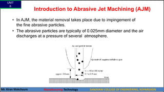
The AJM unit normally operates at a pressure of 0.2-1.0 N/mm2 .
The composition of gas and a high velocity has a significant impact on the MRR
even if the mixing ratio is not changed.
The Nozzle
The nozzle is one of the most vital elements controlling the process
characteristics.
The nozzle material should be hard to avoid any significant wear due to the
flowing abrasive. [Normally WC (avg. life: 12-30 hrs.) or Sapphire (Appr. = 300 hrs.)
are used]
For a normal operation the cross-sectional area of the orifice can be either
circular or rectangular and between 0.05- 0.2mm2 .
UNIT
6
Mr. Kiran Wakchaure Manufacturing Technology SANJIVANI COLLEGE OF ENGINEERING, KOPARGAON
24](https://image.slidesharecdn.com/non-traditional-machining-240310163807-e65c5fd4/85/Advanced-Manufacturing-Processes-UG-Program-24-320.jpg)
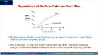
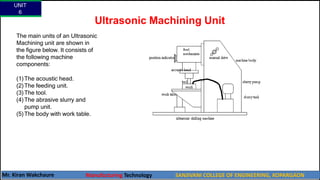
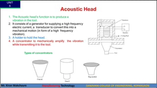
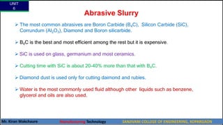

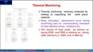
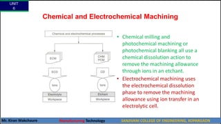
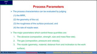
This document discusses non-traditional machining processes. It begins by explaining that non-traditional machining is needed for new materials that cannot be machined through traditional methods. It then classifies non-traditional machining processes into mechanical, thermal, electrochemical, and chemical categories based on the type of energy used. Specific non-traditional machining processes are then described in more detail, including waterjet machining which uses high-pressure water to cut materials, and abrasive jet machining which adds abrasive particles to the water jet to enhance material removal. Applications and advantages and disadvantages of waterjet machining are also provided.


