Download as PDF, PPTX


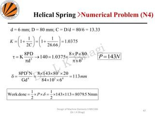
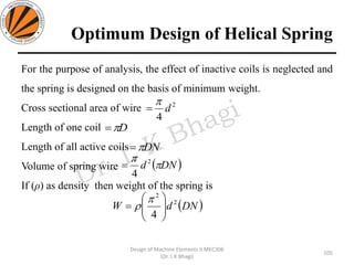
![Design Procedure of Helical Springs
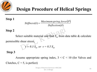
Step 12
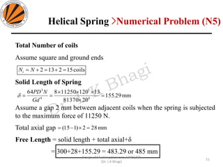
and then calculate, free length= Solid length + total gap+δ
Step 13
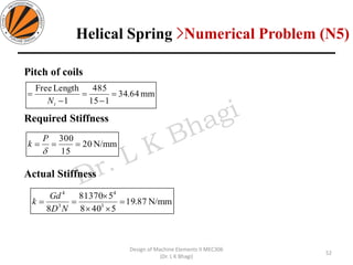
Find the pitch (p) of the coil using
Step 14
And Finally calculate rate of spring using
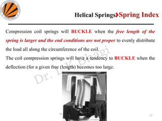
Check to avoid buckling
[Guides not required]
[Guides required]
62
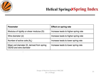
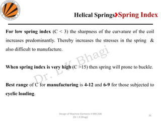
Design of Machine Elements II MEC306
(Dr. L K Bhagi)
ND
Gd
k 3
4
8
=
( )1−
=
tN
lengthFree
p
6.2
diametercoilMean
lengthFree
6.2
diametercoilMean
lengthFree](https://image.slidesharecdn.com/unit-1springs-copy-191105155239/85/Springs-DESIGN-OF-MACHINE-ELEMENTS-II-62-320.jpg)
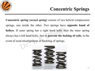

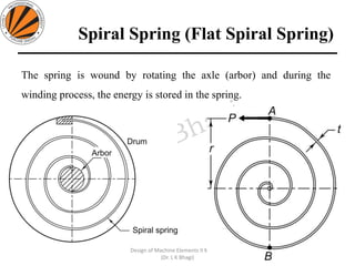


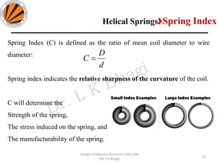
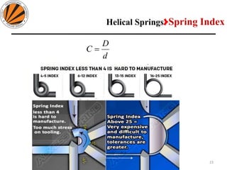
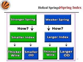
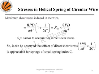
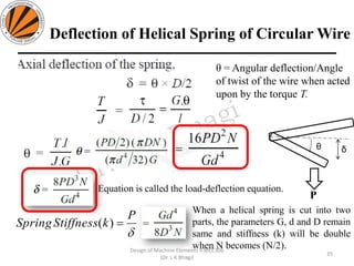
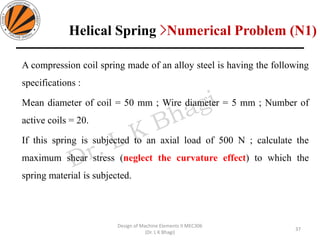
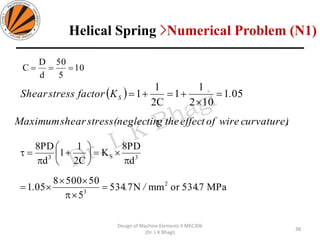
The document provides an overview of springs, detailing their definition, objectives, and types, along with manufacturing processes and material selection criteria. It emphasizes the significance of materials with high fatigue strength and resilience, as well as the effects of spring index on performance and manufacturability. Additionally, it includes numerical examples demonstrating the design calculations for various types of springs.