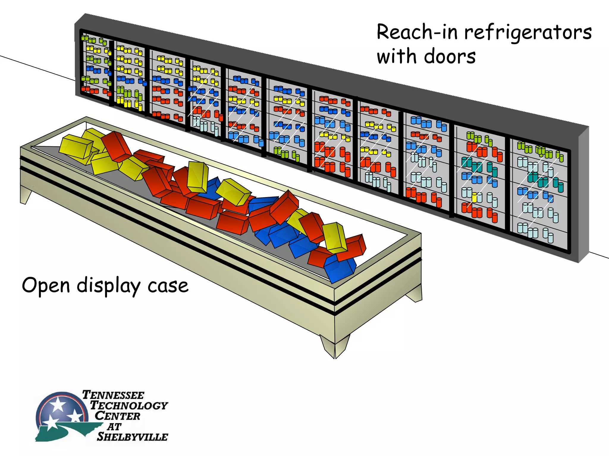
Heating, Ventilating, A ir-C onditioning
                  &
      Refrigeration Technology
SECTION 5
COMMERCIAL REFRIGERATION
        UNIT 26
     APPLICATION OF
 REFRIGERATION SYSTEMS
UNIT OBJECTIVES
 After studying this unit, the reader should
                 be able to

• Describe the different types of display equipment
• Discuss heat reclaim
• Describe package versus remote condensing unit applications
• Describe mullion heat
• Discuss walk-in refrigeration applications
• Describe basic vending machine operation
• Describe basic refrigerated air-dry unit operation
REACH-IN REFRIGERATION
       MERCHANDISING

• Available in high-, medium-, and low-
  temperature ranges
• Open cases – Less efficient but are
  more appealing to the customer
• Closes cases – More efficient but are
  less appealing to the customer
Reach-in refrigerators
                    with doors


Open display case
SELF-CONTAINED REACH-IN
           FIXTURES
• Heat is rejected back into the store (good in the
  winter, bad in the summer)
• Equipment can be moved around easily
• Since each unit is separate, if one system breaks
  down the others are not affected
• Condenser cleaning and condensate removal need
  to be addressed
• Condensate can be used to help cool the
  compressor
Self-contained boxes have their own
          condensing unit
INDIVIDUAL CONDENSING
              UNITS
• Only one system is affected when a breakdown
  occurs
• Condensing units can be located outside or in an
  equipment room
• Air temperature in the equipment room can be
  controlled with dampers
• Rejected heat can be reused to heat the store
  in the winter
MULTIPLE EVAPORATORS AND SINGLE-
    COMPRESSOR APPLICATIONS
          (ADVANTAGES)

• Compressor motors are more efficient
• System heat can be captured for use in
  heating the store (heat reclaim)
• First-stage heat controls the three-way
  heat reclaim valve
• Parallel and series heat reclaim systems
Multiple
 evaporators
connected to a
     single
  compressor
Rooftop air cooled condenser


                                 Duct mounted coil
    Receiver


                   3-way heat reclaim
                   valve
Liquid line    Compressor
Rooftop air cooled condenser


    Receiver         Heat
                     exchanger


                             Pump
Liquid line    Compressor
                                     Water tank
Return air from the
                      structure
Dampers
                            Cooling coil       Supply air to
                                               structure

          Mixed
          air


          Filters                 Blower
 Outside air        Heat reclaim coil      Primary heat source
MULTIPLE EVAPORATORS AND SINGLE-
    COMPRESSOR APPLICATIONS
        (DISADVANTAGES)
• Refrigeration load cannot be easily matched
• Starting of large compressors draws higher
  locked rotor amperage
• Short cycling of large compressors
• Increases power consumption
• Small increases in load may cause large
  compressor to cycle on
PARALLEL COMPRESSOR SYSTEMS

• Often referred to as rack systems
• Uses two or more compressors
• Connected with common suction and discharge
  headers and receiver
• Compressors cycle on an off to satisfy the load
  of the system
• If there are three compressors connected in
  parallel, only one compressor will operate during
  the lowest load period
Vent line
              Oil strainers      Oil
                                 reservoir
                                                     Oil
                                                  separator

 Suction to
compressors


                                                 Discharge
                                                   from
                         Oil level regulators   compressors
ADVANTAGES OF PARALLEL
         COMPRESSORS
•   Load matching
•   Diversification
•   Flexibility
•   Higher efficiencies
•   Lower operating costs
•   Less compressor cycling
DISADVANTAGES OF PARALLEL
       COMPRESSORS
• Leaks affect the entire rack
  – Large leaks will result in the failure of
    multiple remote units
• Compressor burnouts affect the
  entire rack
  – One motor burnout can result in the
    formation of acid in the entire system
  – Extensive cleanup procedure required
LOAD MATCHING

• As the load changes, the common suction
  pressure entering the compressor will vary
• Actual load is sensed by a pressure transducer
• Compressors will cycle on, cycle off, load, or
  unload depending on the load on the system
• Systems can be even (same size compressors)
  or uneven (different size compressors)
SYSTEM PRESSURE REGULATORS
            (SPR)

• Located between the condenser and the receiver
• Utilizes a parallel receiver instead of a series
  receiver
• Controls the amount of liquid in the active
  refrigeration system
• On hot days, the SPR causes refrigerant to enter
  the receiver to maximize the condenser’s
  effective surface area
SECONDARY FLUID
  REFRIGERATION SYSTEMS

• Primary HFC or HCFC refrigerant used to cool
  a secondary refrigerant
• Secondary fluid is usually an antifreeze solution
  and is always a liquid
• Secondary fluid is circulated to individual
  fixtures to absorb box heat
• Heat exchange process then takes place
  between primary and secondary fluids
Condenser
Secondary refrigerant (water)
circuit
                           Evaporator


           Pump

                                Heat
                              exchanger

                              Primary refrigerant
                              circuit

     SECONDAY FLUID REFRIGERATION SYSTEM
                 (SIMPLIFIED)
ADVANTAGES OF SECONDARY
  REFRIGERANT SYSTEMS
• Uses less refrigerant
• Easier to install with less critical piping
• Lower superheat in primary refrigerant
  circuit
• Less complicated defrost cycles
• Less maintenance
• Only low-pressure fluid is located in the
  customer area of store
DISADVANTAGES OF SECONDARY
   REFRIGERANT SYSTEMS
• Higher initial equipment costs
• Added cost of secondary refrigerant
  pumping
• Thicker and better insulation
  required on secondary loop
• Higher cost for low-temperature
  secondary fluids
PRESSURIZED LIQUID SYSTEMS
• Uses a small centrifugal pump to pressurize
  the liquid in the liquid line
• Saturation temperature is raised while liquid
  temperature remains the same
• Liquid will not flash into a vapor if it
  experiences a pressure drop in the line
• Leads to lower condensing temperatures, head
  pressures, and compression ratios which
  increase efficiency
Condenser
Centrifugal pump


                                  Compressor

                   Evaporator
UNITARY STAND-ALONE
    REFRIGERATION SYSTEMS
• Multiple compressor modules located close to
  display cases
• Condensers are cooled by a closed loop fluid
  cooler
• Can be used as to reclaim heat for heating the
  space or hot water
• Refrigerant usage is reduced
• Less piping required, fewer solder joints,
  reduced leak potential
EVAPORATOR TEMPERATURE
         CONTROL
• Multiple evaporators may not operate
  at the same temperature
• Evaporator pressure regulators can
  be used to maintain different
  pressures
• EPR valves are located on all of the
  higher temperature evaporator
  circuits
INTERCONNECTING PIPING IN MULTIPLE
    EVAPORATOR INSTALLATIONS

 • Liquid and suction lines need to be run
   to remote condensing units
 • Suction lines need to be insulated
 • Lines can be run in a pipe chase
 • Lines can be run through individual
   plastic pipes for ease in replacement in
   case of a leak
Refrigerated case


Condensate             System piping
  piping

                    Piping chase
TEMPERATURE CONTROL OF THE FIXTURE
      – MEDIUM TEMPERATURE

• Can be accomplished without
  interconnecting wiring between box and
  condensing unit
• Planned off cycle defrost can be
  controlled from equipment room
• Defrost for the boxes can be staggered
  so each box is defrosted at a different
  time
TEMPERATURE CONTROL OF THE
   FIXTURE – LOW TEMPERATURE

• Heat must be furnished to each evaporator
  (either electric or hot gas)
• Defrost cycles can be staggered
• Heat from other boxes is used for hot gas
  defrost
• Electric heat defrost is easier to
  troubleshoot
HOT GAS DEFROST
• Discharge gas from the compressor is
  directed to the evaporator being defrosted
• The other evaporators can remain in the
  cooling mode while one evaporator is being
  defrosted
• Three-way valves are used to direct the hot
  gas to the defrosting evaporator
• The evaporator in defrost is piped in parallel
  to the condenser
Cooling


Cooling


Cooling                    Solenoid open


                    Receiver

          Accumulator
Cooling


Cooling


Defrost                    Solenoid
                           closed


                    Receiver

          Accumulator
CHEST-TYPE DISPLAY FIXTURES

• Reach-in equipment can have lids or be open
  type
• Fresh vegetables and meat are usually in
  open-type cases
• Evaporators are usually mechanical draft
  and are at the bottom of the display
• Chest-type cases can have remote
  condensing units or be self-contained units
BACK-TO-BACK CHEST-TYPE DISPLAY CASES


    Evaporator
    coils                  Plenum
  Plenum
CLOSED-TYPE CHEST FIXTURES

• Normally low-temperature boxes for ice
  cream and frozen foods
• Lids are a barrier to the customer and are
  not popular
• Upright, closed display with glass doors
  allow customer to see the product
• Upright displays can often be loaded from
  inside the walk-in cooler
DISPLAY CASE/WALK-IN COOLER (PLAN VIEW)

                               Merchandising
                                 displays
                                     Product
                                     Storage

         Walk-in cooler

                                    Customer
                                    access to
                                     product
CONTROLLING SWEATING ON THE
    CABINET OF FIXTURES
• Sweating forms when the cabinet is below
  dew point temperature
• Small (mullion) heaters prevent moisture
  from forming
• Heaters can be controlled based on the
  humidity level in the store
• Stores are kept cool to reduce load on
  the refrigeration equipment
MAINTAINING STORE
       AMBIENT CONDITIONS
• In warm weather, the air-conditioning
  systems remove moisture
• Less humidity in the store means less
  moisture on the evaporator coils
• Reduced defrost time since less ice will
  form on the coils
WALK-IN REFRIGERATION
• Permanently erected
  – Not intended to be moved
  – Larger walk-in boxes are permanently installed
• Knock-down type
  – Constructed of insulated metal panels
  – Can be disassembled and moved if necessary
  – Equipped with interior safety catches to
    prevent someone from becoming locked inside
EVAPORATOR LOCATION IN A WALK-
          IN COOLER
 • Can be piped to remote condensers or
   can be package units
 • Located in the box so the cold air does
   not blow out when the door is opened
 • Some have a fan switch to turn the fan
   off when the door is opened
 • Some systems pump down when the door
   is opened
CONDENSATE REMOVAL
• Drain pan should be piped to the outside
  of the cooler
• On low-temperature applications, the
  drain line needs to be heated
• Drain lines should be pitched downward to
  prevent trapping condensate
Heat tape
  keeps the line
      warm
                   Condensate line
Condensate line       pitched
   run to the        downward
 outside of the
     cooler
REFRIGERATION PIPING
• Standard installations require fittings,
  soldering, leak checking, evacuating
• Line sets are pre-charged flexible lines with
  quick-connect fittings
• Condensing unit and evaporator are also pre-
  charged and have quick-connect fittings
• No soldering or evacuation is required
• Long line sets can be coiled horizontally to aid
  in oil return
Quick-connect fitting on
unit

  Pre-charged tubing line
  with quick-connect
  fitting
VENDING MACHINE REFRIGERATION

• Self-contained refrigerated dispensing machines
• Equipment is similar to domestic refrigerators
• Evaporators operate below freezing
• Usually equipped with low-ambient controls
• Some have self-contained, removable systems
• When a breakdown occurs, the entire unit can be
  replaced
• Health switch – device that will disable the unit if
  the temperature of the storage area is too high
WATER COOLERS
• Water dispensed through a bubbler
• Can use bottled or city water as a source
• Pressure-type systems use supply water pressure
  to dispense water
• Water pressure regulator can be adjusted for
  proper flow
• Evaporator is a small tank with the refrigeration
  lines wrapped around it
• The water that goes down the drain is used to
  either cool incoming water or the refrigerant in
  the liquid line
REFRIGERATED AIR DRIERS
• Process of dehydrating air, removing moisture
• Air used in pneumatic controls must be dry
• Air is cooled down below dew point to allow the
  moisture to condense
• The evaporator in the heat exchanger operates
  just above freezing
• Hot gas bypass provides a false load on the
  system to prevent freeze ups
• The hot gas bypass is usually controlled by the
  suction pressure of the system
SUMMARY
• Refrigerated cases can be either open or closed
• Closed cases are more efficient than open cases
• Self-contained units have their own compressor
  and are not affected if other systems fail
• Larger compressors can be used to service multiple
  units and evaporators
• Heat from multiple evaporator systems can be
  used to heat the store or domestic water
• Parallel compressor (rack) systems use a bank of
  compressors to control multiple systems
SUMMARY
• Compressors cycle on an off to satisfy the load of
  the system
• Rack systems are more efficient than multiple units
  with individual compressors
• Leaks in a rack system affects the entire system
• Rack systems have the advantage of load matching
• System pressure regulators utilize parallel
  receivers to adjust the amount of refrigerant in
  the active circuit
• Secondary refrigerant systems use an HFC or
  HCFC refrigerant to cool a secondary liquid (usually
  a water/antifreeze mixture)
SUMMARY
• Secondary fluid is circulated to the remote units
• Heat exchanges take place between the remote unit
  and the secondary refrigerant as well as between
  the primary and secondary refrigerants
• Secondary refrigerant systems require less
  maintenance than conventional refrigeration systems
• Pressurized liquid systems use small centrifugal
  pumps to pressurize the liquid in the liquid line
• Pressurized liquid systems operate with lower
  condensing temperatures, head pressures, and
  compression ratios which increase efficiency
SUMMARY
• Evaporator pressure regulators can be used to
  maintain different pressures in multiple evaporator
  systems
• Suction and liquid lines need to be field installed to
  connect the evaporator to the condensing units
• Refrigerant lines can be run in pipe chases to
  provide access for servicing and repair
• Medium temperature systems can be defrosted by
  random, planned or off cycle methods
• Low temperature systems can be defrosted by hot
  gas or by external electric heaters
SUMMARY
• Cabinet sweating can be reduced by mullion heaters
• Evaporators should be located so that cool air is not
  blown from the box when the door is opened
• Walk-in refrigeration systems can be permanently
  erected or knock-down units
• Condensate must be removed from the box
• Drain lines on low temperature systems should be
  heated to keep them warm
• Condensate lines should be pitched to aid in the
  condensate removal
SUMMARY
• Refrigerant piping can be accomplished with
  pre-charged line sets
• Refrigerated vending machines are self-
  contained units
• Evaporators on water coolers are small tanks
  with refrigeration lines wrapped around it
• Refrigerated air driers are used to remove
  moisture from air used in pneumatic controls
  systems

Unit 26

  • 1.
    Heating, Ventilating, Air-C onditioning & Refrigeration Technology
  • 2.
    SECTION 5 COMMERCIAL REFRIGERATION UNIT 26 APPLICATION OF REFRIGERATION SYSTEMS
  • 3.
    UNIT OBJECTIVES Afterstudying this unit, the reader should be able to • Describe the different types of display equipment • Discuss heat reclaim • Describe package versus remote condensing unit applications • Describe mullion heat • Discuss walk-in refrigeration applications • Describe basic vending machine operation • Describe basic refrigerated air-dry unit operation
  • 4.
    REACH-IN REFRIGERATION MERCHANDISING • Available in high-, medium-, and low- temperature ranges • Open cases – Less efficient but are more appealing to the customer • Closes cases – More efficient but are less appealing to the customer
  • 5.
    Reach-in refrigerators with doors Open display case
  • 6.
    SELF-CONTAINED REACH-IN FIXTURES • Heat is rejected back into the store (good in the winter, bad in the summer) • Equipment can be moved around easily • Since each unit is separate, if one system breaks down the others are not affected • Condenser cleaning and condensate removal need to be addressed • Condensate can be used to help cool the compressor
  • 7.
    Self-contained boxes havetheir own condensing unit
  • 8.
    INDIVIDUAL CONDENSING UNITS • Only one system is affected when a breakdown occurs • Condensing units can be located outside or in an equipment room • Air temperature in the equipment room can be controlled with dampers • Rejected heat can be reused to heat the store in the winter
  • 9.
    MULTIPLE EVAPORATORS ANDSINGLE- COMPRESSOR APPLICATIONS (ADVANTAGES) • Compressor motors are more efficient • System heat can be captured for use in heating the store (heat reclaim) • First-stage heat controls the three-way heat reclaim valve • Parallel and series heat reclaim systems
  • 10.
  • 11.
    Rooftop air cooledcondenser Duct mounted coil Receiver 3-way heat reclaim valve Liquid line Compressor
  • 12.
    Rooftop air cooledcondenser Receiver Heat exchanger Pump Liquid line Compressor Water tank
  • 13.
    Return air fromthe structure Dampers Cooling coil Supply air to structure Mixed air Filters Blower Outside air Heat reclaim coil Primary heat source
  • 14.
    MULTIPLE EVAPORATORS ANDSINGLE- COMPRESSOR APPLICATIONS (DISADVANTAGES) • Refrigeration load cannot be easily matched • Starting of large compressors draws higher locked rotor amperage • Short cycling of large compressors • Increases power consumption • Small increases in load may cause large compressor to cycle on
  • 15.
    PARALLEL COMPRESSOR SYSTEMS •Often referred to as rack systems • Uses two or more compressors • Connected with common suction and discharge headers and receiver • Compressors cycle on an off to satisfy the load of the system • If there are three compressors connected in parallel, only one compressor will operate during the lowest load period
  • 16.
    Vent line Oil strainers Oil reservoir Oil separator Suction to compressors Discharge from Oil level regulators compressors
  • 17.
    ADVANTAGES OF PARALLEL COMPRESSORS • Load matching • Diversification • Flexibility • Higher efficiencies • Lower operating costs • Less compressor cycling
  • 18.
    DISADVANTAGES OF PARALLEL COMPRESSORS • Leaks affect the entire rack – Large leaks will result in the failure of multiple remote units • Compressor burnouts affect the entire rack – One motor burnout can result in the formation of acid in the entire system – Extensive cleanup procedure required
  • 19.
    LOAD MATCHING • Asthe load changes, the common suction pressure entering the compressor will vary • Actual load is sensed by a pressure transducer • Compressors will cycle on, cycle off, load, or unload depending on the load on the system • Systems can be even (same size compressors) or uneven (different size compressors)
  • 20.
    SYSTEM PRESSURE REGULATORS (SPR) • Located between the condenser and the receiver • Utilizes a parallel receiver instead of a series receiver • Controls the amount of liquid in the active refrigeration system • On hot days, the SPR causes refrigerant to enter the receiver to maximize the condenser’s effective surface area
  • 21.
    SECONDARY FLUID REFRIGERATION SYSTEMS • Primary HFC or HCFC refrigerant used to cool a secondary refrigerant • Secondary fluid is usually an antifreeze solution and is always a liquid • Secondary fluid is circulated to individual fixtures to absorb box heat • Heat exchange process then takes place between primary and secondary fluids
  • 22.
    Condenser Secondary refrigerant (water) circuit Evaporator Pump Heat exchanger Primary refrigerant circuit SECONDAY FLUID REFRIGERATION SYSTEM (SIMPLIFIED)
  • 23.
    ADVANTAGES OF SECONDARY REFRIGERANT SYSTEMS • Uses less refrigerant • Easier to install with less critical piping • Lower superheat in primary refrigerant circuit • Less complicated defrost cycles • Less maintenance • Only low-pressure fluid is located in the customer area of store
  • 24.
    DISADVANTAGES OF SECONDARY REFRIGERANT SYSTEMS • Higher initial equipment costs • Added cost of secondary refrigerant pumping • Thicker and better insulation required on secondary loop • Higher cost for low-temperature secondary fluids
  • 25.
    PRESSURIZED LIQUID SYSTEMS •Uses a small centrifugal pump to pressurize the liquid in the liquid line • Saturation temperature is raised while liquid temperature remains the same • Liquid will not flash into a vapor if it experiences a pressure drop in the line • Leads to lower condensing temperatures, head pressures, and compression ratios which increase efficiency
  • 26.
    Condenser Centrifugal pump Compressor Evaporator
  • 27.
    UNITARY STAND-ALONE REFRIGERATION SYSTEMS • Multiple compressor modules located close to display cases • Condensers are cooled by a closed loop fluid cooler • Can be used as to reclaim heat for heating the space or hot water • Refrigerant usage is reduced • Less piping required, fewer solder joints, reduced leak potential
  • 28.
    EVAPORATOR TEMPERATURE CONTROL • Multiple evaporators may not operate at the same temperature • Evaporator pressure regulators can be used to maintain different pressures • EPR valves are located on all of the higher temperature evaporator circuits
  • 29.
    INTERCONNECTING PIPING INMULTIPLE EVAPORATOR INSTALLATIONS • Liquid and suction lines need to be run to remote condensing units • Suction lines need to be insulated • Lines can be run in a pipe chase • Lines can be run through individual plastic pipes for ease in replacement in case of a leak
  • 30.
    Refrigerated case Condensate System piping piping Piping chase
  • 31.
    TEMPERATURE CONTROL OFTHE FIXTURE – MEDIUM TEMPERATURE • Can be accomplished without interconnecting wiring between box and condensing unit • Planned off cycle defrost can be controlled from equipment room • Defrost for the boxes can be staggered so each box is defrosted at a different time
  • 32.
    TEMPERATURE CONTROL OFTHE FIXTURE – LOW TEMPERATURE • Heat must be furnished to each evaporator (either electric or hot gas) • Defrost cycles can be staggered • Heat from other boxes is used for hot gas defrost • Electric heat defrost is easier to troubleshoot
  • 33.
    HOT GAS DEFROST •Discharge gas from the compressor is directed to the evaporator being defrosted • The other evaporators can remain in the cooling mode while one evaporator is being defrosted • Three-way valves are used to direct the hot gas to the defrosting evaporator • The evaporator in defrost is piped in parallel to the condenser
  • 34.
    Cooling Cooling Cooling Solenoid open Receiver Accumulator
  • 35.
    Cooling Cooling Defrost Solenoid closed Receiver Accumulator
  • 36.
    CHEST-TYPE DISPLAY FIXTURES •Reach-in equipment can have lids or be open type • Fresh vegetables and meat are usually in open-type cases • Evaporators are usually mechanical draft and are at the bottom of the display • Chest-type cases can have remote condensing units or be self-contained units
  • 37.
    BACK-TO-BACK CHEST-TYPE DISPLAYCASES Evaporator coils Plenum Plenum
  • 38.
    CLOSED-TYPE CHEST FIXTURES •Normally low-temperature boxes for ice cream and frozen foods • Lids are a barrier to the customer and are not popular • Upright, closed display with glass doors allow customer to see the product • Upright displays can often be loaded from inside the walk-in cooler
  • 39.
    DISPLAY CASE/WALK-IN COOLER(PLAN VIEW) Merchandising displays Product Storage Walk-in cooler Customer access to product
  • 40.
    CONTROLLING SWEATING ONTHE CABINET OF FIXTURES • Sweating forms when the cabinet is below dew point temperature • Small (mullion) heaters prevent moisture from forming • Heaters can be controlled based on the humidity level in the store • Stores are kept cool to reduce load on the refrigeration equipment
  • 41.
    MAINTAINING STORE AMBIENT CONDITIONS • In warm weather, the air-conditioning systems remove moisture • Less humidity in the store means less moisture on the evaporator coils • Reduced defrost time since less ice will form on the coils
  • 42.
    WALK-IN REFRIGERATION • Permanentlyerected – Not intended to be moved – Larger walk-in boxes are permanently installed • Knock-down type – Constructed of insulated metal panels – Can be disassembled and moved if necessary – Equipped with interior safety catches to prevent someone from becoming locked inside
  • 43.
    EVAPORATOR LOCATION INA WALK- IN COOLER • Can be piped to remote condensers or can be package units • Located in the box so the cold air does not blow out when the door is opened • Some have a fan switch to turn the fan off when the door is opened • Some systems pump down when the door is opened
  • 44.
    CONDENSATE REMOVAL • Drainpan should be piped to the outside of the cooler • On low-temperature applications, the drain line needs to be heated • Drain lines should be pitched downward to prevent trapping condensate
  • 45.
    Heat tape keeps the line warm Condensate line Condensate line pitched run to the downward outside of the cooler
  • 46.
    REFRIGERATION PIPING • Standardinstallations require fittings, soldering, leak checking, evacuating • Line sets are pre-charged flexible lines with quick-connect fittings • Condensing unit and evaporator are also pre- charged and have quick-connect fittings • No soldering or evacuation is required • Long line sets can be coiled horizontally to aid in oil return
  • 47.
    Quick-connect fitting on unit Pre-charged tubing line with quick-connect fitting
  • 48.
    VENDING MACHINE REFRIGERATION •Self-contained refrigerated dispensing machines • Equipment is similar to domestic refrigerators • Evaporators operate below freezing • Usually equipped with low-ambient controls • Some have self-contained, removable systems • When a breakdown occurs, the entire unit can be replaced • Health switch – device that will disable the unit if the temperature of the storage area is too high
  • 49.
    WATER COOLERS • Waterdispensed through a bubbler • Can use bottled or city water as a source • Pressure-type systems use supply water pressure to dispense water • Water pressure regulator can be adjusted for proper flow • Evaporator is a small tank with the refrigeration lines wrapped around it • The water that goes down the drain is used to either cool incoming water or the refrigerant in the liquid line
  • 50.
    REFRIGERATED AIR DRIERS •Process of dehydrating air, removing moisture • Air used in pneumatic controls must be dry • Air is cooled down below dew point to allow the moisture to condense • The evaporator in the heat exchanger operates just above freezing • Hot gas bypass provides a false load on the system to prevent freeze ups • The hot gas bypass is usually controlled by the suction pressure of the system
  • 51.
    SUMMARY • Refrigerated casescan be either open or closed • Closed cases are more efficient than open cases • Self-contained units have their own compressor and are not affected if other systems fail • Larger compressors can be used to service multiple units and evaporators • Heat from multiple evaporator systems can be used to heat the store or domestic water • Parallel compressor (rack) systems use a bank of compressors to control multiple systems
  • 52.
    SUMMARY • Compressors cycleon an off to satisfy the load of the system • Rack systems are more efficient than multiple units with individual compressors • Leaks in a rack system affects the entire system • Rack systems have the advantage of load matching • System pressure regulators utilize parallel receivers to adjust the amount of refrigerant in the active circuit • Secondary refrigerant systems use an HFC or HCFC refrigerant to cool a secondary liquid (usually a water/antifreeze mixture)
  • 53.
    SUMMARY • Secondary fluidis circulated to the remote units • Heat exchanges take place between the remote unit and the secondary refrigerant as well as between the primary and secondary refrigerants • Secondary refrigerant systems require less maintenance than conventional refrigeration systems • Pressurized liquid systems use small centrifugal pumps to pressurize the liquid in the liquid line • Pressurized liquid systems operate with lower condensing temperatures, head pressures, and compression ratios which increase efficiency
  • 54.
    SUMMARY • Evaporator pressureregulators can be used to maintain different pressures in multiple evaporator systems • Suction and liquid lines need to be field installed to connect the evaporator to the condensing units • Refrigerant lines can be run in pipe chases to provide access for servicing and repair • Medium temperature systems can be defrosted by random, planned or off cycle methods • Low temperature systems can be defrosted by hot gas or by external electric heaters
  • 55.
    SUMMARY • Cabinet sweatingcan be reduced by mullion heaters • Evaporators should be located so that cool air is not blown from the box when the door is opened • Walk-in refrigeration systems can be permanently erected or knock-down units • Condensate must be removed from the box • Drain lines on low temperature systems should be heated to keep them warm • Condensate lines should be pitched to aid in the condensate removal
  • 56.
    SUMMARY • Refrigerant pipingcan be accomplished with pre-charged line sets • Refrigerated vending machines are self- contained units • Evaporators on water coolers are small tanks with refrigeration lines wrapped around it • Refrigerated air driers are used to remove moisture from air used in pneumatic controls systems