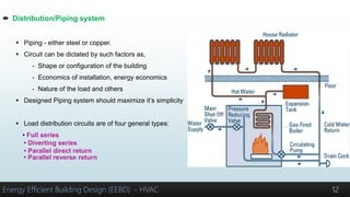
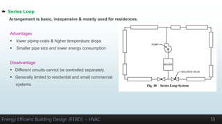
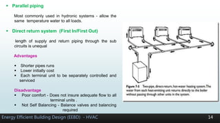
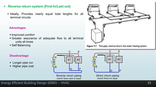
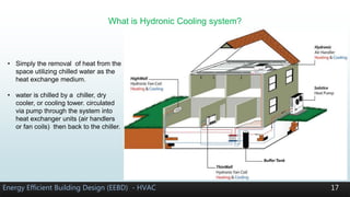
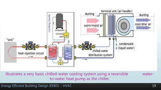
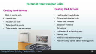
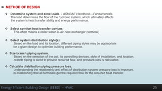
Hydronic Heating & Cooling
System Design
Energy Efficient Building Design (EEBD) - HVAC
Presenter
Kshitiz Pandit
1
What is Hydronic System?
 A hydronic system - composed of pumps, primary equipment (boilers, chillers)
piping, fittings, coils and control valves.
 Hydronic Heating system
 Hydronic Cooling system
Energy Efficient Building Design (EEBD) - HVAC 2
• Water is heated at boiler (gas, fuel, electric)
• Systems can be designed to handle multiple zones
• Water flows through piping that connects a boiler,
water heater, or chiller to suitable terminal heat
transfer units located at the space or process.
 Hot-water heating system opposed to steam and forced-warm-air heating systems.
Energy Efficient Building Design (EEBD) - HVAC 3
Pros
• More flexible than low-pressure steam
systems wide variation in temperatures
• Comfortable humidity levels.
• Less energy is used to circulate water
than blow air through the ducts.
• Quiet operation.
• Easy zoning.
Cons
• High initial installation cost, compared to forced-
warm-air (FWA) heating systems.
• Slower heat response
• Stagnant air caused by lack of ventilation
• Condensation in some Hydronic cooling systems
 Water systems can be classified by 1) Operating temperature 3) Flow generation
2) Pressurization 4) Piping arrangement
5) Pumping arrangement
Temperature classification
Energy Efficient Building Design (EEBD) - HVAC 4
I. Low-temperature water (LTW)
max. allowable working pressure =1100KPa
max. temp = 120°C.
• Low temp. heating system generally in
residential and small commercial building.
II. High-temperature water (HTW)
Operates at 175°C < temp. Max. 200°C
Usually at pressure about 2 Mpa
• High temp. heating system is widely used in
high rise, commercial and industrial buildings
Energy Efficient Building Design (EEBD) - HVAC 5
iii. Chilled-water (CW)
For cooling, normally operate with
a design supply water temp. of 4 to 13°C (usually
7°C), at a pressure ≤ 830 kPa.
• Antifreeze or brine solutions may be used
temp. < 4°C or for coil freeze protection.
• Well-water systems can use supply temperatures
of 15°C or higher.
iv. Dual temperature water (DTW)
Combine heating &cooling.
circulate hot & /or chilled water through
common piping and terminal heat transfer
apparatus.
• it operates within the pressure and
temperature limits of LTW system.
water temp. at winter 38°C to 65°C
summer 4°C to 7°C.
 CLOSED WATER SYSTEMS
Most hot and chilled water systems are closed.
These fundamental components are
• Loads
• Source
• Expansion chamber
• Pump
• Distribution system
Theoretically, a hydronic system could operate with only these five components.
The components are subdivided into two groups: thermal and hydraulic.
 Thermal components consist of - load, source, and expansion chamber.
 Hydraulic components consist of the distribution system, pump, and expansion chamber.
 The expansion chamber is the only component that serves both a thermal and a hydraulic function
Energy Efficient Building Design (EEBD) - HVAC 6
 Load
• A device that causes heat to flow out of or into the system to or from the space or process
• It is the independent variable to which the remainder of the system must respond.
• Outward heat flow characterizes a heating system
• Inward heat flow characterizes a cooling system.
Energy Efficient Building Design (EEBD) - HVAC 7
 Heat Source
 The source is the point where heat is added to (heating) or
removed from (cooling) the system
 Boiler - appliance that heats water using oil, gas, or electricity
as a heat source.
Energy Efficient Building Design (EEBD) - HVAC 8
• Hot-water generator or boiler
• Steam-to-water heat exchanger
• Water-to-water heat exchanger
• Solar heating panels
• Exhaust gas heat exchanger
• Incinerator heat exchanger
• Heat pump condenser
• Air-to-water heat exchanger
 Expansion chamber
 Also called an expansion or compression tank.
 It serves both a thermal and a hydraulic function.
It accommodate volumetric changes (water expand on heating)
and prevents excess pressure.
 Standard expansion tank is a large tank located above the boiler.
 Expansion tanks are of three basic configurations:
(1) A closed tank - which contains a captured volume of
compressed air and water, with an air/water
interface (sometimes called a plain steel tank)
(2) An open tank (i.e., a tank open to the atmosphere)
(3) A diaphragm tank - In which a flexible membrane is inserted
between the air and the water.
Energy Efficient Building Design (EEBD) - HVAC 9
 Pump/Pumping system
 Circulator/centrifugal pumps
 Most common type in hydronic system.
 Force hot water from heat source through piping to heat transfer units
and back to the boiler using centrifugal force.
 Pumps may be installed in parallel or series configurations.
 Air-source heat pumps, work best in well-insulated and airtight homes.
 Most hydronic heat pumps list a COP of between 3.0 and 3.5
 Variable-speed drives are becoming economical.
Two types:
 Parallel pumping
 Series pumping
Energy Efficient Building Design (EEBD) - HVAC 10
Energy Efficient Building Design (EEBD) - HVAC 11
Primary/secondary or compound pumping
 Distribution/Piping system
 Piping - either steel or copper.
 Circuit can be dictated by such factors as,
- Shape or configuration of the building
- Economics of installation, energy economics
- Nature of the load and others
 Designed Piping system should maximize it’s simplicity
 Load distribution circuits are of four general types:
• Full series
• Diverting series
• Parallel direct return
• Parallel reverse return
Energy Efficient Building Design (EEBD) - HVAC 12
 Series Loop
Arrangement is basic, inexpensive & mostly used for residences.
Advantages
 lower piping costs & higher temperature drops
 Smaller pipe size and lower energy consumption
Disadvantage
 Different circuits cannot be controlled separately.
 Generally limited to residential and small commercial
systems.
Energy Efficient Building Design (EEBD) - HVAC 13
Energy Efficient Building Design (EEBD) - HVAC 14
 Parallel piping
Most commonly used in hydronic systems - allow the
same temperature water to all loads.
 Direct return system (First In/First Out)
length of supply and return piping through the sub
circuits is unequal
Advantages
 Shorter pipes runs
 Lower initially cost
 Each terminal unit to be separately controlled and
serviced
Disadvantage
 Poor comfort - Does not insure adequate flow to all
terminal units .
 Not Self Balancing - Balance valves and balancing
required
Energy Efficient Building Design (EEBD) - HVAC 15
 Reverse return system (First In/Last out)
 Ideally, Provides nearly equal total lengths for all
terminal circuits.
Advantages
 Improved comfort
 Greater assurance of adequate flow to all terminal
units all times
 Self Balancing
Disadvantage
 Longer pipe run
 Higher pipe cost
 Non residential Heating Systems
Possible approaches to enhance the economics of large heating systems include
 Higher supply temperatures
 Primary-secondary pumping
 Terminal equipment designed for smaller flow rates.
The three techniques may be used either singly or in combination.
Energy Efficient Building Design (EEBD) - HVAC 16
 Combination piping system
• It is combination of some of four basic ways.
• It takes the best features of each.
• It is chosen for high rise building where separate control is not needed.
• Mainly reverse return system is coupled with other systems.
• It is simple and has low cost as compared to complete reverse return
What is Hydronic Cooling system?
Energy Efficient Building Design (EEBD) - HVAC 17
• Simply the removal of heat from the
space utilizing chilled water as the
heat exchange medium.
• water is chilled by a chiller, dry
cooler, or cooling tower. circulated
via pump through the system into
heat exchanger units (air handlers
or fan coils) then back to the chiller.
 Benefits of CHILLED WATER Cooling System
 Reduced electrical energy usage
 Availability of many chillers
 Easy zoning
 Adaptability to radiant panel cooling
 Adaptability to chilled-beam cooling
 Lower refrigerant volume
 Adaptability to thermal storage
Energy Efficient Building Design (EEBD) - HVAC 18
Energy Efficient Building Design (EEBD) - HVAC 19
illustrates a very basic chilled-water cooling system using a reversible water-
to-water heat pump as the chiller.
 Chilled Water Sources
 Geothermal water to water heat pumps
 Electrically driven air to water heat pumps
 Air cooled condenser
 Direct lake water cooling
 Ground well water cooling
Energy Efficient Building Design (EEBD) - HVAC 20
Energy Efficient Building Design (EEBD) - HVAC 21
Dual temperature system
Energy Efficient Building Design (EEBD) - HVAC 22
Cooling Source Devices
• Electric compression chiller
• Thermal absorption chiller
• Heat pump evaporator
• Air-to-water heat exchanger
• Water-to-water heat exchanger
Energy Efficient Building Design (EEBD) - HVAC 23
Heating load devices
• Heating coils in central units
• Zone or central reheat coils
• Finned-tube radiators
• Baseboard radiators
• Convectors
• Unit heaters & air handling units
• Fan-coil units
• Water-to-water heat exchangers
• Radiant heating panels &Snow-melting panels
Cooling load devices
Coils in central units
• Fan-coil units
• Induction unit coils
• Radiant cooling panels
• Water-to-water heat exchangers
Terminal Heat transfer units
The principles and procedures for designing and selecting piping and components for low-temperature water,
chilled water, and dual-temperature water systems.
Principle
Energy Efficient Building Design (EEBD) - HVAC 24
Effective and economical water system
design is affected by complex relationships
between the various system components.
The design water temperature, flow rate,
piping layout, pump selection, terminal unit
selection, and control method are all
interrelated.
In a practical sense, no component can be selected
without considering its effect on the other elements.
For example, design water temperature and flow
rates are interrelated, as are the system layout and
pump selection. The type and control of heat
exchangers used affect the flow rate and pump
selection, and the pump selection and distribution
affect the controllability
 METHOD OF DESIGN
 Determine system and zone loads - ASHRAE Handbook—Fundamentals.
The load determines the flow of the hydronic system, which ultimately affects
the system’s heat transfer ability and energy performance.
 Select comfort heat transfer devices
This often means a coiler water-to-air heat exchanger (terminal)
 Select system distribution style(s).
Based on the load and its location, different piping styles may be appropriate
for a given design to optimize building performance.
 Size branch piping system.
Based on the selection of the coil, its controlling devices, style of installation, and location,
branch piping is sized to provide required flow, and pressure loss is calculated.
 Calculate distribution piping pressure loss.
understanding the relationship and effect of distribution system pressure loss is important
in establishing that all terminals get the required flow for the required heat transfer.
Energy Efficient Building Design (EEBD) - HVAC 25
 Lay out piping system and size pipes.
After preliminary calculations of target friction loss for the pipes, sketch the system..
 Select pump specialties.
 Select air management methodology.
All hydronic systems entrain air in the circulated fluid. Managing
the collection of that air as it leaves the working fluid is essential
to management of system pressure and the safe operation of
system components
 Select pump (hydraulic components).
Unless a system is very small (e.g., a residential hot-water heating system), the pump is
selected to fit the system. A significant portion of energy use in a hydronic system is transporting the
fluid through the distribution system. Proper pump selection limits this energy use, whereas improper
selection leads to energy inefficiency and poor distribution and heat transfer.
 Determine installation details, iterate design.
Increase performance and cost effectiveness
Energy Efficient Building Design (EEBD) - HVAC 26
27 References
2008 ASHRAE Handbook—HVAC Systems and Equipment. ASHRAE, 1791 Tullie
Circle, Atlanta, Georgia.
https://www.ahscansw.com.au/sites/default/files/idronics_13_us.pdf
Energy Efficient Building Design (EEBD) - HVAC 28

Hydronic heating & cooling system design presentation

  • 1.
    Hydronic Heating &Cooling System Design Energy Efficient Building Design (EEBD) - HVAC Presenter Kshitiz Pandit 1
  • 2.
    What is HydronicSystem?  A hydronic system - composed of pumps, primary equipment (boilers, chillers) piping, fittings, coils and control valves.  Hydronic Heating system  Hydronic Cooling system Energy Efficient Building Design (EEBD) - HVAC 2 • Water is heated at boiler (gas, fuel, electric) • Systems can be designed to handle multiple zones • Water flows through piping that connects a boiler, water heater, or chiller to suitable terminal heat transfer units located at the space or process.
  • 3.
     Hot-water heatingsystem opposed to steam and forced-warm-air heating systems. Energy Efficient Building Design (EEBD) - HVAC 3 Pros • More flexible than low-pressure steam systems wide variation in temperatures • Comfortable humidity levels. • Less energy is used to circulate water than blow air through the ducts. • Quiet operation. • Easy zoning. Cons • High initial installation cost, compared to forced- warm-air (FWA) heating systems. • Slower heat response • Stagnant air caused by lack of ventilation • Condensation in some Hydronic cooling systems
  • 4.
     Water systemscan be classified by 1) Operating temperature 3) Flow generation 2) Pressurization 4) Piping arrangement 5) Pumping arrangement Temperature classification Energy Efficient Building Design (EEBD) - HVAC 4 I. Low-temperature water (LTW) max. allowable working pressure =1100KPa max. temp = 120°C. • Low temp. heating system generally in residential and small commercial building. II. High-temperature water (HTW) Operates at 175°C < temp. Max. 200°C Usually at pressure about 2 Mpa • High temp. heating system is widely used in high rise, commercial and industrial buildings
  • 5.
    Energy Efficient BuildingDesign (EEBD) - HVAC 5 iii. Chilled-water (CW) For cooling, normally operate with a design supply water temp. of 4 to 13°C (usually 7°C), at a pressure ≤ 830 kPa. • Antifreeze or brine solutions may be used temp. < 4°C or for coil freeze protection. • Well-water systems can use supply temperatures of 15°C or higher. iv. Dual temperature water (DTW) Combine heating &cooling. circulate hot & /or chilled water through common piping and terminal heat transfer apparatus. • it operates within the pressure and temperature limits of LTW system. water temp. at winter 38°C to 65°C summer 4°C to 7°C.
  • 6.
     CLOSED WATERSYSTEMS Most hot and chilled water systems are closed. These fundamental components are • Loads • Source • Expansion chamber • Pump • Distribution system Theoretically, a hydronic system could operate with only these five components. The components are subdivided into two groups: thermal and hydraulic.  Thermal components consist of - load, source, and expansion chamber.  Hydraulic components consist of the distribution system, pump, and expansion chamber.  The expansion chamber is the only component that serves both a thermal and a hydraulic function Energy Efficient Building Design (EEBD) - HVAC 6
  • 7.
     Load • Adevice that causes heat to flow out of or into the system to or from the space or process • It is the independent variable to which the remainder of the system must respond. • Outward heat flow characterizes a heating system • Inward heat flow characterizes a cooling system. Energy Efficient Building Design (EEBD) - HVAC 7
  • 8.
     Heat Source The source is the point where heat is added to (heating) or removed from (cooling) the system  Boiler - appliance that heats water using oil, gas, or electricity as a heat source. Energy Efficient Building Design (EEBD) - HVAC 8 • Hot-water generator or boiler • Steam-to-water heat exchanger • Water-to-water heat exchanger • Solar heating panels • Exhaust gas heat exchanger • Incinerator heat exchanger • Heat pump condenser • Air-to-water heat exchanger
  • 9.
     Expansion chamber Also called an expansion or compression tank.  It serves both a thermal and a hydraulic function. It accommodate volumetric changes (water expand on heating) and prevents excess pressure.  Standard expansion tank is a large tank located above the boiler.  Expansion tanks are of three basic configurations: (1) A closed tank - which contains a captured volume of compressed air and water, with an air/water interface (sometimes called a plain steel tank) (2) An open tank (i.e., a tank open to the atmosphere) (3) A diaphragm tank - In which a flexible membrane is inserted between the air and the water. Energy Efficient Building Design (EEBD) - HVAC 9
  • 10.
     Pump/Pumping system Circulator/centrifugal pumps  Most common type in hydronic system.  Force hot water from heat source through piping to heat transfer units and back to the boiler using centrifugal force.  Pumps may be installed in parallel or series configurations.  Air-source heat pumps, work best in well-insulated and airtight homes.  Most hydronic heat pumps list a COP of between 3.0 and 3.5  Variable-speed drives are becoming economical. Two types:  Parallel pumping  Series pumping Energy Efficient Building Design (EEBD) - HVAC 10
  • 11.
    Energy Efficient BuildingDesign (EEBD) - HVAC 11 Primary/secondary or compound pumping
  • 12.
     Distribution/Piping system Piping - either steel or copper.  Circuit can be dictated by such factors as, - Shape or configuration of the building - Economics of installation, energy economics - Nature of the load and others  Designed Piping system should maximize it’s simplicity  Load distribution circuits are of four general types: • Full series • Diverting series • Parallel direct return • Parallel reverse return Energy Efficient Building Design (EEBD) - HVAC 12
  • 13.
     Series Loop Arrangementis basic, inexpensive & mostly used for residences. Advantages  lower piping costs & higher temperature drops  Smaller pipe size and lower energy consumption Disadvantage  Different circuits cannot be controlled separately.  Generally limited to residential and small commercial systems. Energy Efficient Building Design (EEBD) - HVAC 13
  • 14.
    Energy Efficient BuildingDesign (EEBD) - HVAC 14  Parallel piping Most commonly used in hydronic systems - allow the same temperature water to all loads.  Direct return system (First In/First Out) length of supply and return piping through the sub circuits is unequal Advantages  Shorter pipes runs  Lower initially cost  Each terminal unit to be separately controlled and serviced Disadvantage  Poor comfort - Does not insure adequate flow to all terminal units .  Not Self Balancing - Balance valves and balancing required
  • 15.
    Energy Efficient BuildingDesign (EEBD) - HVAC 15  Reverse return system (First In/Last out)  Ideally, Provides nearly equal total lengths for all terminal circuits. Advantages  Improved comfort  Greater assurance of adequate flow to all terminal units all times  Self Balancing Disadvantage  Longer pipe run  Higher pipe cost
  • 16.
     Non residentialHeating Systems Possible approaches to enhance the economics of large heating systems include  Higher supply temperatures  Primary-secondary pumping  Terminal equipment designed for smaller flow rates. The three techniques may be used either singly or in combination. Energy Efficient Building Design (EEBD) - HVAC 16  Combination piping system • It is combination of some of four basic ways. • It takes the best features of each. • It is chosen for high rise building where separate control is not needed. • Mainly reverse return system is coupled with other systems. • It is simple and has low cost as compared to complete reverse return
  • 17.
    What is HydronicCooling system? Energy Efficient Building Design (EEBD) - HVAC 17 • Simply the removal of heat from the space utilizing chilled water as the heat exchange medium. • water is chilled by a chiller, dry cooler, or cooling tower. circulated via pump through the system into heat exchanger units (air handlers or fan coils) then back to the chiller.
  • 18.
     Benefits ofCHILLED WATER Cooling System  Reduced electrical energy usage  Availability of many chillers  Easy zoning  Adaptability to radiant panel cooling  Adaptability to chilled-beam cooling  Lower refrigerant volume  Adaptability to thermal storage Energy Efficient Building Design (EEBD) - HVAC 18
  • 19.
    Energy Efficient BuildingDesign (EEBD) - HVAC 19 illustrates a very basic chilled-water cooling system using a reversible water- to-water heat pump as the chiller.
  • 20.
     Chilled WaterSources  Geothermal water to water heat pumps  Electrically driven air to water heat pumps  Air cooled condenser  Direct lake water cooling  Ground well water cooling Energy Efficient Building Design (EEBD) - HVAC 20
  • 21.
    Energy Efficient BuildingDesign (EEBD) - HVAC 21 Dual temperature system
  • 22.
    Energy Efficient BuildingDesign (EEBD) - HVAC 22 Cooling Source Devices • Electric compression chiller • Thermal absorption chiller • Heat pump evaporator • Air-to-water heat exchanger • Water-to-water heat exchanger
  • 23.
    Energy Efficient BuildingDesign (EEBD) - HVAC 23 Heating load devices • Heating coils in central units • Zone or central reheat coils • Finned-tube radiators • Baseboard radiators • Convectors • Unit heaters & air handling units • Fan-coil units • Water-to-water heat exchangers • Radiant heating panels &Snow-melting panels Cooling load devices Coils in central units • Fan-coil units • Induction unit coils • Radiant cooling panels • Water-to-water heat exchangers Terminal Heat transfer units
  • 24.
    The principles andprocedures for designing and selecting piping and components for low-temperature water, chilled water, and dual-temperature water systems. Principle Energy Efficient Building Design (EEBD) - HVAC 24 Effective and economical water system design is affected by complex relationships between the various system components. The design water temperature, flow rate, piping layout, pump selection, terminal unit selection, and control method are all interrelated. In a practical sense, no component can be selected without considering its effect on the other elements. For example, design water temperature and flow rates are interrelated, as are the system layout and pump selection. The type and control of heat exchangers used affect the flow rate and pump selection, and the pump selection and distribution affect the controllability
  • 25.
     METHOD OFDESIGN  Determine system and zone loads - ASHRAE Handbook—Fundamentals. The load determines the flow of the hydronic system, which ultimately affects the system’s heat transfer ability and energy performance.  Select comfort heat transfer devices This often means a coiler water-to-air heat exchanger (terminal)  Select system distribution style(s). Based on the load and its location, different piping styles may be appropriate for a given design to optimize building performance.  Size branch piping system. Based on the selection of the coil, its controlling devices, style of installation, and location, branch piping is sized to provide required flow, and pressure loss is calculated.  Calculate distribution piping pressure loss. understanding the relationship and effect of distribution system pressure loss is important in establishing that all terminals get the required flow for the required heat transfer. Energy Efficient Building Design (EEBD) - HVAC 25
  • 26.
     Lay outpiping system and size pipes. After preliminary calculations of target friction loss for the pipes, sketch the system..  Select pump specialties.  Select air management methodology. All hydronic systems entrain air in the circulated fluid. Managing the collection of that air as it leaves the working fluid is essential to management of system pressure and the safe operation of system components  Select pump (hydraulic components). Unless a system is very small (e.g., a residential hot-water heating system), the pump is selected to fit the system. A significant portion of energy use in a hydronic system is transporting the fluid through the distribution system. Proper pump selection limits this energy use, whereas improper selection leads to energy inefficiency and poor distribution and heat transfer.  Determine installation details, iterate design. Increase performance and cost effectiveness Energy Efficient Building Design (EEBD) - HVAC 26
  • 27.
    27 References 2008 ASHRAEHandbook—HVAC Systems and Equipment. ASHRAE, 1791 Tullie Circle, Atlanta, Georgia. https://www.ahscansw.com.au/sites/default/files/idronics_13_us.pdf
  • 28.
    Energy Efficient BuildingDesign (EEBD) - HVAC 28

Editor's Notes

  • #3 Hydronics is the use of water as the heat-transfer medium in heating and cooling systems.
  • #4 Hydronics is the use of water as the heat-transfer medium in heating and cooling systems.
  • #9 Boiler can use more than one source. Cast iron boiler common in residential. Copper water tube boiler – efficient, LMB smaller n less capacity.
  • #10 Open tanks, in older systems, introduce air into the system, enhance piping corrosion.
  • #11 In Variable flow drive , flow varies acc. To demand. adjusting the speed of the electric motor , Ultimately saves energy, Parallel Pumping. Each pump operates at the same pressure, and provides its share of the system flow at that pressure Generally, pumps of equal size are used. Series pumping each pump operates at the same flow rate and provides its share of the total pressure at that flow
  • #12 It reduces the size and cost of the distribution system It may use larger flows and lower temperatures in the terminal or secondary circuits. A primary pump circulates water in the primary distribution system while one or more secondary pumps circulate the terminal circuits. The connection between primary and secondary circuits provides complete hydraulic isolation of both circuits and allows a controlled interchange of water between the two. Thus, a high supply water temperature can be used in the primary circuit at a low flow rate and high temperature drop, while a lower temperature and conventional temperature drop can be used in the secondary circuit(s).
  • #13  A variety of insulation materials are used in hydronic piping systems
  • #19  All electrical input -cooling distribution system -ultimately heat gain to the building. when high energy efficiency - minimize the electrical input power -to operate the cooling distribution system. Hydronic delivery options -lower electrical energy usage than a thermally equivalent “all air” system. Such as water-to-water heat pumps, air-to-water heat etc Ceiling surfaces -ideal for absorbing heat from the occupied space below. (handle sensible portion of cooling load) specially designed heat absorption units -use chilled water to generate a gentle cooling airflow within a room using natural convection. In Europe An air-to-water heat pump –heat n cool - well-insulated thermal storage tank. Is warm n chilled-transfer thermal energy betn load n tank.
  • #22  Dual-temperature systems are used when the same load devices and distribution systems are used for both heating and cooling (e.g.,fan-coil units and central station air-handling unit coils) 4 pipe system is more expensive, amount of piping is roughly doubled, but overall occupant comfort is greatly improved.
  • #24 Natural convection units Forced-convection units Radiation units
  • #26 The methodology is not a rigid framework, but rather a flexible outline that should be adapted by the designer to suit current needs. ASHRAE Handbook—Fundamentals. Several load calculation procedures