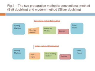
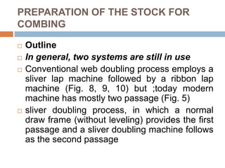
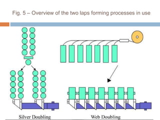
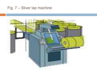
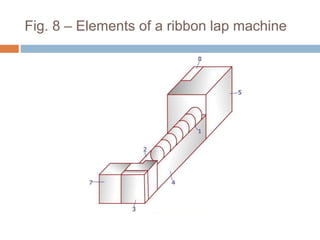
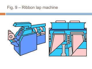
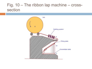
SlideShare a Scribd company logo
PREPARATION OF
COMBING
Preparation of combing
 The combers are fed with a small lap produced by
combining several slivers. It is extremely
important that these laps are prepared properly,
as the raw material delivered by the card is
unsuitable for combing as regards both form and
fiber arrangement.
 If card slivers were just combined and fed to the
comber, true nipping by the nipper plates would
occur only on the high points, with the risk that the
nippers could not retain the less firmly
compressed edge zones of the slivers (Fig. 1).
This is because the slivers are not flattened.
Fig. 1– Clamped slivers between the nipper plates
The fibres could then be pulled out as clumps by the
circular combs during combing operation. A sheet with the
greatest possible degree of evenness in cross section, with
uniform thickness is therefore required as in-feed to the
comber.
Fig. 2 – Fibers projecting from the nippers
 Good parallel disposition of the fibers within the
sheet, along the length of the lap sheet is a further
prerequisite. If the fibers lie across the strand,
even long fibers shown as “b” (Fig. 2) are
presented to the circular combs as if they were
short fibers and get eliminated as noil. A short
fibre is shown as “a”. Even though the fibre “b” is
longer than “a”, its extent along the material
passage is same as that of “a”. Hence, it also treat
like the fibre “a”. This means a long fibre is
unnecessary lost as noil. Appropriate preparatory
machines are needed to prepare the material so
that it meets requirements.
The fiber arrangement must also be taken into
account, i.e. in this case the disposition of the
hooks. If the comber is to straighten hooks, as it is
intended to, then the fibers must be presented to it
with leading hooks. The carded slivers have trailing
hooks as the majority hooks (more than 50%) as the
sliver emerges out of the calendar rollers in the
carding machine. Each time the sliver is packed in a
can and taken out, the majority hooks change. For
example, as the sliver is withdrawn from the card
can, the original trailing hooks (as the sliver went
into the can) are now counted as the leading hooks
as can be seen in Fig. 3. Hence, at this stage
majority hooks are the leading hooks.
Fig. 3 Sliver passage from carding to
comber
 As it can be seen from the Fig. 3 , having even
number of processes in between card and the
comber will ensure that the majority hooks as
they are presented to combing are leading
hooks.
 In earlier days sliver lap and ribbon lap
machines were used. During the nineteen-
nineties the sliver lap machine / ribbon lap
machine process was replaced by the draw
frame / sliver doubling machine process over
all staple ranges.
Fig.4 – The two preparation methods: conventional method
(Batt doubling) and modern method (Sliver doubling)
How does the material preparation affect
Combing?
 The degree of parallelization has a very great
influence on the result of the combing operation,
both from the viewpoint of both economics and
quality. Very high level of parallelization also has
adverse effect on combing as that of poor
parallelization. It is important to find the optimum
level of parallelization. Lack of parallelization and
longitudinal orientation, leads to elimination of
longer fibers together with the noil, as already
explained. Loss of good fibers due to fiber
disorder is reinforced to the extent that the circular
combs are overloaded during passage through a
disordered batt. Due to this, they pluck and tear at
the stock, thereby carrying away bunches of
fibers.
Parallelization of the Fibers in the
Batt
 Similar phenomenon happens with an excessively thick batt.
With same machine settings, the amount of noil decreases
proportionately with increased parallelization of the fibers and
with a decrease in batt thickness (below the optimum). It
therefore does not always mean that more noil is
automatically associated with better yarn quality. The correct
goal is always a predetermined waste elimination level.
 On the other hand, an understanding of the disadvantages of
excessive longitudinal fiber orientation needs a better
understanding of the combing process and in particular what
is happening at the detaching stage. While detaching,
between one fifth and one sixth of the fibers presented to the
detaching rollers are drawn out of the batt. This means only
few fibers are drawn out of a thick layer of feedstock.
Parallelization of the Fibers in the
Batt
 During this stage, impurities, neps, foreign matter and so on are held back in the
sheet because of the retaining power of the thick layer. This retaining power, and
hence the so-called self-cleaning effect of the batt, will be all the greater the higher
the disorder of the fibers within the sheet.
 If the fibers have an excessively high degree of parallelization, the retaining power of
the batt can be so severely reduced that it is no longer able to hold back the neps as
it usually does. Some of these neps also pass through the top comb. Neppiness of
the product is increased.
 A second disadvantage is that if the fibers are too highly ordered, the single layers of
the lap do not hold together well (it lacks cohesive strength of the layers compared
with that of the fiber-to-fiber adhesion at the surface of the lap layers) and mutual
separation layer from layer is disturbed.
 A high degree of parallelization always leads to considerable hairiness of the lap.
Furthermore, the lap weight must be kept low. The degree of parallelization depends
on the total draft between the card and the comber.
Batt Thickness (weight)
 The self-cleaning effect of the batt exerts a considerable influence on
the combing operation. This effect arises from the retaining power of
the fibers relative to impurities, which depends not only on the disorder
of the fibers but also on their quantity. A thick batt always exerts greater
retaining power than a thin one. At least up to a certain level, the
clamping effect of the nippers is also better with a higher batt volume.
 Adversely, a thick batt always exerts a heavy load on the comb and this
can lead to uncontrolled combing. In this case, the fiber farthest from
the circular combs (upper side of the nipped web) may escape the
combing operation, since the combs are no longer able to pass through
the whole of the layer.
 The unfavorable effect of overloading the comb is greater than the
favorable effect of the retaining power of the sheet. A compromise must
therefore be struck between quality and productivity. Depending on
staple length (and Micronaire value), the ideal batt weight lies between
72 and 80 ktex for short and medium staple cotton, and between 64
and 74 ktex for long staple cotton, for fibre length longer than 1 ¼
inches.
Evenness of the Batt Sheet
 The more even the batt sheet (web) is across its width, the better the
clamping effect at the nipper clamping line. Evening-out of the web is
therefore of considerable significance. It is very important that the
slivers are arranged neatly relative to one another and evenly over the
entire working width at the lap machine.
 The most effective method of obtaining a high degree of evenness of
the sheet is high doubling in sheet form, as in the classical system, a
combination of sliver lap machine and ribbon lap machine (Fig. 4).
 In this respect, the operation of the ribbon lap machine was always
ideal in the past. Nowadays, however, the disadvantages far exceed
the advantages, e.g. the very high fiber parallelization. Caused by the
high drafts in two stages, resulting in insufficient cohesion of the sheet.
It does not permit high speeds and therefore high productivity
compared with the sliver lap system. The self-cleaning effect also
suffers from this high degree of parallelization.
The Disposition of the Hooks
 Fibers must be presented to the comber so that leading hooks
predominate in the feedstock. This influences not only the opening
out of the hooks themselves, but also the cleanliness of the web. If
the batt is fed in the wrong direction, the number of neps rises
markedly. It also increases the soiling and loading of top combs and
circular combs, and finally the neppiness.
 Both quantity and form of fiber hooks depend mainly upon the
stiffness of the fibers; the latter rises to the second or third power
with increasing coarseness of the fibers (Micronaire value). The
hooks also display different forms; fine, long fibers will always
exhibit more and longer hooks (horseshoe shape) than short,
coarse fibers (hockey-stick shape).
 The role of fiber hooks in the spinning process therefore becomes
more significant as fibers become finer. When short fibers are being
spun, fiber hooks are of secondary importance.
PREPARATION OF THE STOCK FOR
COMBING
 Outline
 In general, two systems are still in use
 Conventional web doubling process employs a
sliver lap machine followed by a ribbon lap
machine (Fig. 8, 9, 10) but ;today modern
machine has mostly two passage (Fig. 5)
 sliver doubling process, in which a normal
draw frame (without leveling) provides the first
passage and a sliver doubling machine follows
as the second passage
Fig. 5 – Overview of the two laps forming processes in use
Conventional System
 In this process the sliver lap machine (Fig. 6,
7) is the first step machine in which. 24 slivers
from the card are usually fed together and side
by side over a table into a drafting
arrangement.
 By this process a loose form of web is created
with a small draft of around 1.5. After pressing
and smoothing, this web is rolled up to a lap
by calendar rollers.
Fig. 6 – Top view of a sliver lap machine
Fig. 7 – Sliver lap machine
Fig. 8 – Elements of a ribbon lap machine
Fig. 9 – Ribbon lap machine
Fig. 10 – The ribbon lap machine – cross-
section
Modern Preparation System :
The first machines using this system
Fig. 11 – Basic design of the former (lap forming machine)
Fig. 12 – Web Former
 The idea of creating a comber feeding lap by a single web forming process directly in
front of the comber using a draw frame passage in front of this web former, is developed
in 1948 by a Company, called the super lap machine.
 Although all later machines are of different designs they all are based on this idea. That
is why modern high-performance preparation systems will now be explained on the basis
of the machinery manufacturers machines, starting with the first designs.
 As already mentioned, the web former (e.g. Web Former) always follows a normal draw
frame. On the Web Former machine the material flow starts with the creel 1(Fig.11 & 12)
, consisting of two feed rails. In normal operation 12 cans are laid out under each roller-
assisted feed table.
 Altogether, finally gives a total of 24 doublings. The pre-draw frame slivers run over a
guide bridge above the service alley and also over several guide rollers to the drafting
system at 2(Fig. 11 & 13) .
 The web created by the draft of 1.3 to 2.5 passes over two deflecting plates (Fig. 8) onto
the web table on which the webs are superimposed. Calendar rollers draw these
superimposed webs from the table to the lap winding assembly.
 The strong compression created between the calendar rollers forms a new web, which is
rolled into a lap in the lap forming assembly.
 Empty tubes are automatically exchanged for full laps. Transport of the laps to the
In-feed
Fig. 13–The drafting arrangement of a Web Former
 The first part of the machine is a creel on each side material is feed using
two drafting arrangements from maximum. 28 cans obtained from the draw
frame.
 Here also the slivers are guided over a service alley (one on each side) to
the drafting arrangement (Fig.13).
 The Web Former machine features a 3-over-3 roller, two-zone drafting
arrangement
 The pneumatically weighted top rollers can be continuously adjusted from
minimum to maximum per top roller.
 Draft distances are individually variable, and the draft levels in each of the
break and main draft zones are also variables.
 Upper and lower clearer aprons in combination with a suction system keep
the rollers clean.
 The easily accessible drive for the drafting arrangement is in an enclosed
housing and is fitted with appropriate change gears and oil spray
lubrication.
The Lap Winding Assembly – Conventional
System
 After passing through the web table, web runs through four calendar
rollers (Fig. 14, 1). The pressure generated by two membrane
cylinders can be adjusted up to 16 000 N.
 The calendar rollers are followed by two winding rolls (2) and a lap
tube holding device (3) with a lap weighting device. Final lap is
obtained through calendaring process and quality of lap depends on
lap winding assembly.
 The required weighting pressure (up to 10 000 N), derived from a
piston, is transferred via a pivoting lever to the weighting frame and
thus to the lap tube.
 The Web Former has an automatic lap pressure control which adapts
the pressure according to the lap diameter.
 This is due to increase in diameter of the lap raises the weighting
frame, so that pressure increases according to the diameter.
 The increasing size of the lap is adjusted using setting screws. The
machine stops when a preset lap length is reached, whereupon an
automatic device replaces the full lap by an empty tube.
Fig. 14 – The lap winding device of Web
Former
Former speed control arrangement on the Web Former
:
Fig. 15 – Speed diagram of the Web Former, Production gain by speed
control
 In the former system the Web Former machine
did not run at constant speed, since this would
mean choosing the speed according to the most
critical phase of lap winding, i.e. when lap
winding was close to completion.
 However, this meant losing productivity. That is
why machinery manufacturers adapted the speed
of the machine to the buildup of the lap by means
of the speed control set (Fig. 15).
 So, for example, if a final speed of about 70
m/min was required, the machine started with a
speed of 140 m/min.
System Incorporating the Latest
Technology
 Since production speeds using the winding system based
on calendar rollers have reached their limit due to the
system itself, machinery manufacturers developed a new
lap winding system (Fig. 16).
 The new lap winding system makes use of a unique belt
tension and pressure arrangement.
 The winding belt (Fig. 17, 1), with a width similar to that of
the laps, surrounds the lap to form a circumferential
pressure area (modern-shaped) ranging from 180° to
270° from starting to full lap.
 Fiber guidance and pressure distribution applied by the
modern principle allow constant production (i.e. constant
speed during winding of the lap) at speeds of up to 180
m/min over the entire lap buildup.
Fig. 16 – Comparison between different winding systems
Fig. 17 – Modern winding process

More Related Content

What's hot

What's hot (20)

Simplex machine. Roving, sliver
Simplex machine. Roving, sliverSimplex machine. Roving, sliver
Simplex machine. Roving, sliver
 
Carding (1)
Carding (1)Carding (1)
Carding (1)
 
Draw frame
Draw frameDraw frame
Draw frame
 
Double lift and single cylinder
Double lift and single cylinderDouble lift and single cylinder
Double lift and single cylinder
 
Optimisation of drawframe autoleveller
Optimisation of drawframe autolevellerOptimisation of drawframe autoleveller
Optimisation of drawframe autoleveller
 
Jute spinning assingnment_MD. SALIM RANA_DUET
Jute spinning assingnment_MD. SALIM RANA_DUETJute spinning assingnment_MD. SALIM RANA_DUET
Jute spinning assingnment_MD. SALIM RANA_DUET
 
Tertiary motion of a loom
Tertiary motion of a loomTertiary motion of a loom
Tertiary motion of a loom
 
Secondary motions
 Secondary motions Secondary motions
Secondary motions
 
Rotor spinning
Rotor spinningRotor spinning
Rotor spinning
 
Draw frame
Draw frameDraw frame
Draw frame
 
Take up mechanism
Take up mechanismTake up mechanism
Take up mechanism
 
Differents parts of Simplex Machine and their Functions
Differents parts of Simplex Machine and their FunctionsDifferents parts of Simplex Machine and their Functions
Differents parts of Simplex Machine and their Functions
 
Drafting Zone Of Roving/Speed/Simplex Frame Machine
Drafting Zone Of Roving/Speed/Simplex Frame MachineDrafting Zone Of Roving/Speed/Simplex Frame Machine
Drafting Zone Of Roving/Speed/Simplex Frame Machine
 
Study on the Automation in Speed Frame
Study on the Automation in Speed FrameStudy on the Automation in Speed Frame
Study on the Automation in Speed Frame
 
Simplex frame
Simplex frameSimplex frame
Simplex frame
 
Fibrefiness
FibrefinessFibrefiness
Fibrefiness
 
Ring frame
Ring frame Ring frame
Ring frame
 
Blowroom
BlowroomBlowroom
Blowroom
 
Warping
WarpingWarping
Warping
 
Combing
CombingCombing
Combing
 

Viewers also liked (16)

Presentation
PresentationPresentation
Presentation
 
Comber and combing action
Comber and combing action Comber and combing action
Comber and combing action
 
Comber 2015
Comber 2015Comber 2015
Comber 2015
 
Math problem of combing machine
Math problem of combing machineMath problem of combing machine
Math problem of combing machine
 
Combing Behaviors at Different Parameters
Combing Behaviors at Different ParametersCombing Behaviors at Different Parameters
Combing Behaviors at Different Parameters
 
Auto motion in comber
Auto motion in comberAuto motion in comber
Auto motion in comber
 
Control of waste in comber
Control of waste in comberControl of waste in comber
Control of waste in comber
 
Spinning Sampling Technical Presentation
Spinning Sampling Technical PresentationSpinning Sampling Technical Presentation
Spinning Sampling Technical Presentation
 
Modern Blowroom
Modern Blowroom Modern Blowroom
Modern Blowroom
 
Carding machine
Carding machineCarding machine
Carding machine
 
Yarn manufacturing Process : Carding
Yarn manufacturing Process : CardingYarn manufacturing Process : Carding
Yarn manufacturing Process : Carding
 
Yarn calculations By Samrat Dewan
Yarn calculations By Samrat DewanYarn calculations By Samrat Dewan
Yarn calculations By Samrat Dewan
 
Spinning Process
Spinning Process Spinning Process
Spinning Process
 
Sizing
SizingSizing
Sizing
 
State of the Word 2011
State of the Word 2011State of the Word 2011
State of the Word 2011
 
Slideshare ppt
Slideshare pptSlideshare ppt
Slideshare ppt
 

Similar to 1.3 preparation of combing

Similar to 1.3 preparation of combing (20)

Mechanics of Composite Materials
Mechanics of Composite MaterialsMechanics of Composite Materials
Mechanics of Composite Materials
 
Cotton spun-yarns-for-knit-and-woven-fabrics
Cotton spun-yarns-for-knit-and-woven-fabricsCotton spun-yarns-for-knit-and-woven-fabrics
Cotton spun-yarns-for-knit-and-woven-fabrics
 
Abhi rana)4. dry laid non woven fabrics
Abhi rana)4. dry laid non woven fabricsAbhi rana)4. dry laid non woven fabrics
Abhi rana)4. dry laid non woven fabrics
 
Week1-1.pdf
Week1-1.pdfWeek1-1.pdf
Week1-1.pdf
 
6.3 woven fabric
6.3 woven fabric6.3 woven fabric
6.3 woven fabric
 
THE COMBING PROCESS.pptx
THE COMBING PROCESS.pptxTHE COMBING PROCESS.pptx
THE COMBING PROCESS.pptx
 
Yarn spining...
Yarn spining...Yarn spining...
Yarn spining...
 
Some lessons of Weaving
Some lessons of WeavingSome lessons of Weaving
Some lessons of Weaving
 
DRAWFRAME PRESENTATION
DRAWFRAME PRESENTATION DRAWFRAME PRESENTATION
DRAWFRAME PRESENTATION
 
carding
cardingcarding
carding
 
Yarn Manufacturing Process : Comber Part I
Yarn Manufacturing Process : Comber Part IYarn Manufacturing Process : Comber Part I
Yarn Manufacturing Process : Comber Part I
 
Draw frame (1)
Draw frame (1)Draw frame (1)
Draw frame (1)
 
spinning
spinningspinning
spinning
 
Drawing frame and its machine parts
Drawing frame and its machine partsDrawing frame and its machine parts
Drawing frame and its machine parts
 
Yarn evenness_AyBee Marwat
Yarn evenness_AyBee MarwatYarn evenness_AyBee Marwat
Yarn evenness_AyBee Marwat
 
Basics of Fabric Manufacturing
Basics of Fabric ManufacturingBasics of Fabric Manufacturing
Basics of Fabric Manufacturing
 
yarn count in friction spinning
yarn count in friction spinningyarn count in friction spinning
yarn count in friction spinning
 
Draw Frame lecture 1.pptx
Draw Frame lecture 1.pptxDraw Frame lecture 1.pptx
Draw Frame lecture 1.pptx
 
Needle punching nonwovens
Needle punching nonwovensNeedle punching nonwovens
Needle punching nonwovens
 
WRAP AND FRICTION SPINNING SYSTEM
WRAP AND FRICTION SPINNING SYSTEMWRAP AND FRICTION SPINNING SYSTEM
WRAP AND FRICTION SPINNING SYSTEM
 

More from Amit Biswas

Military Textile
Military TextileMilitary Textile
Military TextileAmit Biswas
 
CV & Cover letter
CV & Cover letterCV & Cover letter
CV & Cover letterAmit Biswas
 
Basic structure of a woven fabric
Basic structure of a woven fabricBasic structure of a woven fabric
Basic structure of a woven fabricAmit Biswas
 
Jet dyeing Machine
Jet dyeing MachineJet dyeing Machine
Jet dyeing MachineAmit Biswas
 
Yarn manufacturing process
Yarn manufacturing processYarn manufacturing process
Yarn manufacturing processAmit Biswas
 
Principal Stitches in Weft Knitting
Principal Stitches  in  Weft KnittingPrincipal Stitches  in  Weft Knitting
Principal Stitches in Weft KnittingAmit Biswas
 
Internal & external communication systems of Grameenphone LTD.
Internal & external communication  systems of Grameenphone LTD.Internal & external communication  systems of Grameenphone LTD.
Internal & external communication systems of Grameenphone LTD.Amit Biswas
 
Internal Communication Systems In Grameenphone LTD.
Internal Communication Systems In Grameenphone LTD.Internal Communication Systems In Grameenphone LTD.
Internal Communication Systems In Grameenphone LTD.Amit Biswas
 
Acrylic fibre_Assignment
Acrylic fibre_AssignmentAcrylic fibre_Assignment
Acrylic fibre_AssignmentAmit Biswas
 
Ultrasonic welding machine
Ultrasonic welding machineUltrasonic welding machine
Ultrasonic welding machineAmit Biswas
 
Heritage side in bd
Heritage side in bdHeritage side in bd
Heritage side in bdAmit Biswas
 
FESTIVALS IN BANGLADESH
  FESTIVALS  IN       BANGLADESH  FESTIVALS  IN       BANGLADESH
FESTIVALS IN BANGLADESHAmit Biswas
 
Bangladesh Textile Mills Association (BTMA)
Bangladesh Textile Mills Association  (BTMA)Bangladesh Textile Mills Association  (BTMA)
Bangladesh Textile Mills Association (BTMA)Amit Biswas
 
Presentation - Gear train
Presentation - Gear trainPresentation - Gear train
Presentation - Gear trainAmit Biswas
 
Presentation - Viscose fibre
Presentation - Viscose fibrePresentation - Viscose fibre
Presentation - Viscose fibreAmit Biswas
 

More from Amit Biswas (20)

Military Textile
Military TextileMilitary Textile
Military Textile
 
CV & Cover letter
CV & Cover letterCV & Cover letter
CV & Cover letter
 
Basic structure of a woven fabric
Basic structure of a woven fabricBasic structure of a woven fabric
Basic structure of a woven fabric
 
Jet dyeing Machine
Jet dyeing MachineJet dyeing Machine
Jet dyeing Machine
 
Rapier Loom
Rapier LoomRapier Loom
Rapier Loom
 
Yarn manufacturing process
Yarn manufacturing processYarn manufacturing process
Yarn manufacturing process
 
Yarn count
Yarn countYarn count
Yarn count
 
Sugarcane fibre
Sugarcane fibreSugarcane fibre
Sugarcane fibre
 
Principal Stitches in Weft Knitting
Principal Stitches  in  Weft KnittingPrincipal Stitches  in  Weft Knitting
Principal Stitches in Weft Knitting
 
Internal & external communication systems of Grameenphone LTD.
Internal & external communication  systems of Grameenphone LTD.Internal & external communication  systems of Grameenphone LTD.
Internal & external communication systems of Grameenphone LTD.
 
Report Writting
Report WrittingReport Writting
Report Writting
 
Internal Communication Systems In Grameenphone LTD.
Internal Communication Systems In Grameenphone LTD.Internal Communication Systems In Grameenphone LTD.
Internal Communication Systems In Grameenphone LTD.
 
Acrylic fibre_Assignment
Acrylic fibre_AssignmentAcrylic fibre_Assignment
Acrylic fibre_Assignment
 
Acrylic fibre
Acrylic fibreAcrylic fibre
Acrylic fibre
 
Ultrasonic welding machine
Ultrasonic welding machineUltrasonic welding machine
Ultrasonic welding machine
 
Heritage side in bd
Heritage side in bdHeritage side in bd
Heritage side in bd
 
FESTIVALS IN BANGLADESH
  FESTIVALS  IN       BANGLADESH  FESTIVALS  IN       BANGLADESH
FESTIVALS IN BANGLADESH
 
Bangladesh Textile Mills Association (BTMA)
Bangladesh Textile Mills Association  (BTMA)Bangladesh Textile Mills Association  (BTMA)
Bangladesh Textile Mills Association (BTMA)
 
Presentation - Gear train
Presentation - Gear trainPresentation - Gear train
Presentation - Gear train
 
Presentation - Viscose fibre
Presentation - Viscose fibrePresentation - Viscose fibre
Presentation - Viscose fibre
 

Recently uploaded

Instructions for Submissions thorugh G- Classroom.pptx
Instructions for Submissions thorugh G- Classroom.pptxInstructions for Submissions thorugh G- Classroom.pptx
Instructions for Submissions thorugh G- Classroom.pptxJheel Barad
 
Benefits and Challenges of Using Open Educational Resources
Benefits and Challenges of Using Open Educational ResourcesBenefits and Challenges of Using Open Educational Resources
Benefits and Challenges of Using Open Educational Resourcesdimpy50
 
1.4 modern child centered education - mahatma gandhi-2.pptx
1.4 modern child centered education - mahatma gandhi-2.pptx1.4 modern child centered education - mahatma gandhi-2.pptx
1.4 modern child centered education - mahatma gandhi-2.pptxJosvitaDsouza2
 
Embracing GenAI - A Strategic Imperative
Embracing GenAI - A Strategic ImperativeEmbracing GenAI - A Strategic Imperative
Embracing GenAI - A Strategic ImperativePeter Windle
 
Salient features of Environment protection Act 1986.pptx
Salient features of Environment protection Act 1986.pptxSalient features of Environment protection Act 1986.pptx
Salient features of Environment protection Act 1986.pptxakshayaramakrishnan21
 
How to Break the cycle of negative Thoughts
How to Break the cycle of negative ThoughtsHow to Break the cycle of negative Thoughts
How to Break the cycle of negative ThoughtsCol Mukteshwar Prasad
 
How libraries can support authors with open access requirements for UKRI fund...
How libraries can support authors with open access requirements for UKRI fund...How libraries can support authors with open access requirements for UKRI fund...
How libraries can support authors with open access requirements for UKRI fund...Jisc
 
Synthetic Fiber Construction in lab .pptx
Synthetic Fiber Construction in lab .pptxSynthetic Fiber Construction in lab .pptx
Synthetic Fiber Construction in lab .pptxPavel ( NSTU)
 
Phrasal Verbs.XXXXXXXXXXXXXXXXXXXXXXXXXX
Phrasal Verbs.XXXXXXXXXXXXXXXXXXXXXXXXXXPhrasal Verbs.XXXXXXXXXXXXXXXXXXXXXXXXXX
Phrasal Verbs.XXXXXXXXXXXXXXXXXXXXXXXXXXMIRIAMSALINAS13
 
Industrial Training Report- AKTU Industrial Training Report
Industrial Training Report- AKTU Industrial Training ReportIndustrial Training Report- AKTU Industrial Training Report
Industrial Training Report- AKTU Industrial Training ReportAvinash Rai
 
plant breeding methods in asexually or clonally propagated crops
plant breeding methods in asexually or clonally propagated cropsplant breeding methods in asexually or clonally propagated crops
plant breeding methods in asexually or clonally propagated cropsparmarsneha2
 
How to Split Bills in the Odoo 17 POS Module
How to Split Bills in the Odoo 17 POS ModuleHow to Split Bills in the Odoo 17 POS Module
How to Split Bills in the Odoo 17 POS ModuleCeline George
 
Students, digital devices and success - Andreas Schleicher - 27 May 2024..pptx
Students, digital devices and success - Andreas Schleicher - 27 May 2024..pptxStudents, digital devices and success - Andreas Schleicher - 27 May 2024..pptx
Students, digital devices and success - Andreas Schleicher - 27 May 2024..pptxEduSkills OECD
 
MARUTI SUZUKI- A Successful Joint Venture in India.pptx
MARUTI SUZUKI- A Successful Joint Venture in India.pptxMARUTI SUZUKI- A Successful Joint Venture in India.pptx
MARUTI SUZUKI- A Successful Joint Venture in India.pptxbennyroshan06
 
Jose-Rizal-and-Philippine-Nationalism-National-Symbol-2.pptx
Jose-Rizal-and-Philippine-Nationalism-National-Symbol-2.pptxJose-Rizal-and-Philippine-Nationalism-National-Symbol-2.pptx
Jose-Rizal-and-Philippine-Nationalism-National-Symbol-2.pptxricssacare
 
How to Create Map Views in the Odoo 17 ERP
How to Create Map Views in the Odoo 17 ERPHow to Create Map Views in the Odoo 17 ERP
How to Create Map Views in the Odoo 17 ERPCeline George
 
678020731-Sumas-y-Restas-Para-Colorear.pdf
678020731-Sumas-y-Restas-Para-Colorear.pdf678020731-Sumas-y-Restas-Para-Colorear.pdf
678020731-Sumas-y-Restas-Para-Colorear.pdfCarlosHernanMontoyab2
 
Home assignment II on Spectroscopy 2024 Answers.pdf
Home assignment II on Spectroscopy 2024 Answers.pdfHome assignment II on Spectroscopy 2024 Answers.pdf
Home assignment II on Spectroscopy 2024 Answers.pdfTamralipta Mahavidyalaya
 
Welcome to TechSoup New Member Orientation and Q&A (May 2024).pdf
Welcome to TechSoup   New Member Orientation and Q&A (May 2024).pdfWelcome to TechSoup   New Member Orientation and Q&A (May 2024).pdf
Welcome to TechSoup New Member Orientation and Q&A (May 2024).pdfTechSoup
 

Recently uploaded (20)

Instructions for Submissions thorugh G- Classroom.pptx
Instructions for Submissions thorugh G- Classroom.pptxInstructions for Submissions thorugh G- Classroom.pptx
Instructions for Submissions thorugh G- Classroom.pptx
 
Benefits and Challenges of Using Open Educational Resources
Benefits and Challenges of Using Open Educational ResourcesBenefits and Challenges of Using Open Educational Resources
Benefits and Challenges of Using Open Educational Resources
 
1.4 modern child centered education - mahatma gandhi-2.pptx
1.4 modern child centered education - mahatma gandhi-2.pptx1.4 modern child centered education - mahatma gandhi-2.pptx
1.4 modern child centered education - mahatma gandhi-2.pptx
 
Embracing GenAI - A Strategic Imperative
Embracing GenAI - A Strategic ImperativeEmbracing GenAI - A Strategic Imperative
Embracing GenAI - A Strategic Imperative
 
Salient features of Environment protection Act 1986.pptx
Salient features of Environment protection Act 1986.pptxSalient features of Environment protection Act 1986.pptx
Salient features of Environment protection Act 1986.pptx
 
How to Break the cycle of negative Thoughts
How to Break the cycle of negative ThoughtsHow to Break the cycle of negative Thoughts
How to Break the cycle of negative Thoughts
 
How libraries can support authors with open access requirements for UKRI fund...
How libraries can support authors with open access requirements for UKRI fund...How libraries can support authors with open access requirements for UKRI fund...
How libraries can support authors with open access requirements for UKRI fund...
 
Synthetic Fiber Construction in lab .pptx
Synthetic Fiber Construction in lab .pptxSynthetic Fiber Construction in lab .pptx
Synthetic Fiber Construction in lab .pptx
 
Phrasal Verbs.XXXXXXXXXXXXXXXXXXXXXXXXXX
Phrasal Verbs.XXXXXXXXXXXXXXXXXXXXXXXXXXPhrasal Verbs.XXXXXXXXXXXXXXXXXXXXXXXXXX
Phrasal Verbs.XXXXXXXXXXXXXXXXXXXXXXXXXX
 
Industrial Training Report- AKTU Industrial Training Report
Industrial Training Report- AKTU Industrial Training ReportIndustrial Training Report- AKTU Industrial Training Report
Industrial Training Report- AKTU Industrial Training Report
 
plant breeding methods in asexually or clonally propagated crops
plant breeding methods in asexually or clonally propagated cropsplant breeding methods in asexually or clonally propagated crops
plant breeding methods in asexually or clonally propagated crops
 
NCERT Solutions Power Sharing Class 10 Notes pdf
NCERT Solutions Power Sharing Class 10 Notes pdfNCERT Solutions Power Sharing Class 10 Notes pdf
NCERT Solutions Power Sharing Class 10 Notes pdf
 
How to Split Bills in the Odoo 17 POS Module
How to Split Bills in the Odoo 17 POS ModuleHow to Split Bills in the Odoo 17 POS Module
How to Split Bills in the Odoo 17 POS Module
 
Students, digital devices and success - Andreas Schleicher - 27 May 2024..pptx
Students, digital devices and success - Andreas Schleicher - 27 May 2024..pptxStudents, digital devices and success - Andreas Schleicher - 27 May 2024..pptx
Students, digital devices and success - Andreas Schleicher - 27 May 2024..pptx
 
MARUTI SUZUKI- A Successful Joint Venture in India.pptx
MARUTI SUZUKI- A Successful Joint Venture in India.pptxMARUTI SUZUKI- A Successful Joint Venture in India.pptx
MARUTI SUZUKI- A Successful Joint Venture in India.pptx
 
Jose-Rizal-and-Philippine-Nationalism-National-Symbol-2.pptx
Jose-Rizal-and-Philippine-Nationalism-National-Symbol-2.pptxJose-Rizal-and-Philippine-Nationalism-National-Symbol-2.pptx
Jose-Rizal-and-Philippine-Nationalism-National-Symbol-2.pptx
 
How to Create Map Views in the Odoo 17 ERP
How to Create Map Views in the Odoo 17 ERPHow to Create Map Views in the Odoo 17 ERP
How to Create Map Views in the Odoo 17 ERP
 
678020731-Sumas-y-Restas-Para-Colorear.pdf
678020731-Sumas-y-Restas-Para-Colorear.pdf678020731-Sumas-y-Restas-Para-Colorear.pdf
678020731-Sumas-y-Restas-Para-Colorear.pdf
 
Home assignment II on Spectroscopy 2024 Answers.pdf
Home assignment II on Spectroscopy 2024 Answers.pdfHome assignment II on Spectroscopy 2024 Answers.pdf
Home assignment II on Spectroscopy 2024 Answers.pdf
 
Welcome to TechSoup New Member Orientation and Q&A (May 2024).pdf
Welcome to TechSoup   New Member Orientation and Q&A (May 2024).pdfWelcome to TechSoup   New Member Orientation and Q&A (May 2024).pdf
Welcome to TechSoup New Member Orientation and Q&A (May 2024).pdf
 

1.3 preparation of combing

  • 2. Preparation of combing  The combers are fed with a small lap produced by combining several slivers. It is extremely important that these laps are prepared properly, as the raw material delivered by the card is unsuitable for combing as regards both form and fiber arrangement.  If card slivers were just combined and fed to the comber, true nipping by the nipper plates would occur only on the high points, with the risk that the nippers could not retain the less firmly compressed edge zones of the slivers (Fig. 1). This is because the slivers are not flattened.
  • 3. Fig. 1– Clamped slivers between the nipper plates The fibres could then be pulled out as clumps by the circular combs during combing operation. A sheet with the greatest possible degree of evenness in cross section, with uniform thickness is therefore required as in-feed to the comber.
  • 4. Fig. 2 – Fibers projecting from the nippers
  • 5.  Good parallel disposition of the fibers within the sheet, along the length of the lap sheet is a further prerequisite. If the fibers lie across the strand, even long fibers shown as “b” (Fig. 2) are presented to the circular combs as if they were short fibers and get eliminated as noil. A short fibre is shown as “a”. Even though the fibre “b” is longer than “a”, its extent along the material passage is same as that of “a”. Hence, it also treat like the fibre “a”. This means a long fibre is unnecessary lost as noil. Appropriate preparatory machines are needed to prepare the material so that it meets requirements.
  • 6. The fiber arrangement must also be taken into account, i.e. in this case the disposition of the hooks. If the comber is to straighten hooks, as it is intended to, then the fibers must be presented to it with leading hooks. The carded slivers have trailing hooks as the majority hooks (more than 50%) as the sliver emerges out of the calendar rollers in the carding machine. Each time the sliver is packed in a can and taken out, the majority hooks change. For example, as the sliver is withdrawn from the card can, the original trailing hooks (as the sliver went into the can) are now counted as the leading hooks as can be seen in Fig. 3. Hence, at this stage majority hooks are the leading hooks.
  • 7. Fig. 3 Sliver passage from carding to comber
  • 8.  As it can be seen from the Fig. 3 , having even number of processes in between card and the comber will ensure that the majority hooks as they are presented to combing are leading hooks.  In earlier days sliver lap and ribbon lap machines were used. During the nineteen- nineties the sliver lap machine / ribbon lap machine process was replaced by the draw frame / sliver doubling machine process over all staple ranges.
  • 9. Fig.4 – The two preparation methods: conventional method (Batt doubling) and modern method (Sliver doubling)
  • 10. How does the material preparation affect Combing?  The degree of parallelization has a very great influence on the result of the combing operation, both from the viewpoint of both economics and quality. Very high level of parallelization also has adverse effect on combing as that of poor parallelization. It is important to find the optimum level of parallelization. Lack of parallelization and longitudinal orientation, leads to elimination of longer fibers together with the noil, as already explained. Loss of good fibers due to fiber disorder is reinforced to the extent that the circular combs are overloaded during passage through a disordered batt. Due to this, they pluck and tear at the stock, thereby carrying away bunches of fibers.
  • 11. Parallelization of the Fibers in the Batt  Similar phenomenon happens with an excessively thick batt. With same machine settings, the amount of noil decreases proportionately with increased parallelization of the fibers and with a decrease in batt thickness (below the optimum). It therefore does not always mean that more noil is automatically associated with better yarn quality. The correct goal is always a predetermined waste elimination level.  On the other hand, an understanding of the disadvantages of excessive longitudinal fiber orientation needs a better understanding of the combing process and in particular what is happening at the detaching stage. While detaching, between one fifth and one sixth of the fibers presented to the detaching rollers are drawn out of the batt. This means only few fibers are drawn out of a thick layer of feedstock.
  • 12. Parallelization of the Fibers in the Batt  During this stage, impurities, neps, foreign matter and so on are held back in the sheet because of the retaining power of the thick layer. This retaining power, and hence the so-called self-cleaning effect of the batt, will be all the greater the higher the disorder of the fibers within the sheet.  If the fibers have an excessively high degree of parallelization, the retaining power of the batt can be so severely reduced that it is no longer able to hold back the neps as it usually does. Some of these neps also pass through the top comb. Neppiness of the product is increased.  A second disadvantage is that if the fibers are too highly ordered, the single layers of the lap do not hold together well (it lacks cohesive strength of the layers compared with that of the fiber-to-fiber adhesion at the surface of the lap layers) and mutual separation layer from layer is disturbed.  A high degree of parallelization always leads to considerable hairiness of the lap. Furthermore, the lap weight must be kept low. The degree of parallelization depends on the total draft between the card and the comber.
  • 13. Batt Thickness (weight)  The self-cleaning effect of the batt exerts a considerable influence on the combing operation. This effect arises from the retaining power of the fibers relative to impurities, which depends not only on the disorder of the fibers but also on their quantity. A thick batt always exerts greater retaining power than a thin one. At least up to a certain level, the clamping effect of the nippers is also better with a higher batt volume.  Adversely, a thick batt always exerts a heavy load on the comb and this can lead to uncontrolled combing. In this case, the fiber farthest from the circular combs (upper side of the nipped web) may escape the combing operation, since the combs are no longer able to pass through the whole of the layer.  The unfavorable effect of overloading the comb is greater than the favorable effect of the retaining power of the sheet. A compromise must therefore be struck between quality and productivity. Depending on staple length (and Micronaire value), the ideal batt weight lies between 72 and 80 ktex for short and medium staple cotton, and between 64 and 74 ktex for long staple cotton, for fibre length longer than 1 ¼ inches.
  • 14. Evenness of the Batt Sheet  The more even the batt sheet (web) is across its width, the better the clamping effect at the nipper clamping line. Evening-out of the web is therefore of considerable significance. It is very important that the slivers are arranged neatly relative to one another and evenly over the entire working width at the lap machine.  The most effective method of obtaining a high degree of evenness of the sheet is high doubling in sheet form, as in the classical system, a combination of sliver lap machine and ribbon lap machine (Fig. 4).  In this respect, the operation of the ribbon lap machine was always ideal in the past. Nowadays, however, the disadvantages far exceed the advantages, e.g. the very high fiber parallelization. Caused by the high drafts in two stages, resulting in insufficient cohesion of the sheet. It does not permit high speeds and therefore high productivity compared with the sliver lap system. The self-cleaning effect also suffers from this high degree of parallelization.
  • 15. The Disposition of the Hooks  Fibers must be presented to the comber so that leading hooks predominate in the feedstock. This influences not only the opening out of the hooks themselves, but also the cleanliness of the web. If the batt is fed in the wrong direction, the number of neps rises markedly. It also increases the soiling and loading of top combs and circular combs, and finally the neppiness.  Both quantity and form of fiber hooks depend mainly upon the stiffness of the fibers; the latter rises to the second or third power with increasing coarseness of the fibers (Micronaire value). The hooks also display different forms; fine, long fibers will always exhibit more and longer hooks (horseshoe shape) than short, coarse fibers (hockey-stick shape).  The role of fiber hooks in the spinning process therefore becomes more significant as fibers become finer. When short fibers are being spun, fiber hooks are of secondary importance.
  • 16. PREPARATION OF THE STOCK FOR COMBING  Outline  In general, two systems are still in use  Conventional web doubling process employs a sliver lap machine followed by a ribbon lap machine (Fig. 8, 9, 10) but ;today modern machine has mostly two passage (Fig. 5)  sliver doubling process, in which a normal draw frame (without leveling) provides the first passage and a sliver doubling machine follows as the second passage
  • 17. Fig. 5 – Overview of the two laps forming processes in use
  • 18. Conventional System  In this process the sliver lap machine (Fig. 6, 7) is the first step machine in which. 24 slivers from the card are usually fed together and side by side over a table into a drafting arrangement.  By this process a loose form of web is created with a small draft of around 1.5. After pressing and smoothing, this web is rolled up to a lap by calendar rollers.
  • 19. Fig. 6 – Top view of a sliver lap machine
  • 20. Fig. 7 – Sliver lap machine
  • 21. Fig. 8 – Elements of a ribbon lap machine
  • 22. Fig. 9 – Ribbon lap machine
  • 23. Fig. 10 – The ribbon lap machine – cross- section
  • 24. Modern Preparation System : The first machines using this system Fig. 11 – Basic design of the former (lap forming machine)
  • 25. Fig. 12 – Web Former
  • 26.  The idea of creating a comber feeding lap by a single web forming process directly in front of the comber using a draw frame passage in front of this web former, is developed in 1948 by a Company, called the super lap machine.  Although all later machines are of different designs they all are based on this idea. That is why modern high-performance preparation systems will now be explained on the basis of the machinery manufacturers machines, starting with the first designs.  As already mentioned, the web former (e.g. Web Former) always follows a normal draw frame. On the Web Former machine the material flow starts with the creel 1(Fig.11 & 12) , consisting of two feed rails. In normal operation 12 cans are laid out under each roller- assisted feed table.  Altogether, finally gives a total of 24 doublings. The pre-draw frame slivers run over a guide bridge above the service alley and also over several guide rollers to the drafting system at 2(Fig. 11 & 13) .  The web created by the draft of 1.3 to 2.5 passes over two deflecting plates (Fig. 8) onto the web table on which the webs are superimposed. Calendar rollers draw these superimposed webs from the table to the lap winding assembly.  The strong compression created between the calendar rollers forms a new web, which is rolled into a lap in the lap forming assembly.  Empty tubes are automatically exchanged for full laps. Transport of the laps to the
  • 27. In-feed Fig. 13–The drafting arrangement of a Web Former
  • 28.  The first part of the machine is a creel on each side material is feed using two drafting arrangements from maximum. 28 cans obtained from the draw frame.  Here also the slivers are guided over a service alley (one on each side) to the drafting arrangement (Fig.13).  The Web Former machine features a 3-over-3 roller, two-zone drafting arrangement  The pneumatically weighted top rollers can be continuously adjusted from minimum to maximum per top roller.  Draft distances are individually variable, and the draft levels in each of the break and main draft zones are also variables.  Upper and lower clearer aprons in combination with a suction system keep the rollers clean.  The easily accessible drive for the drafting arrangement is in an enclosed housing and is fitted with appropriate change gears and oil spray lubrication.
  • 29. The Lap Winding Assembly – Conventional System  After passing through the web table, web runs through four calendar rollers (Fig. 14, 1). The pressure generated by two membrane cylinders can be adjusted up to 16 000 N.  The calendar rollers are followed by two winding rolls (2) and a lap tube holding device (3) with a lap weighting device. Final lap is obtained through calendaring process and quality of lap depends on lap winding assembly.  The required weighting pressure (up to 10 000 N), derived from a piston, is transferred via a pivoting lever to the weighting frame and thus to the lap tube.  The Web Former has an automatic lap pressure control which adapts the pressure according to the lap diameter.  This is due to increase in diameter of the lap raises the weighting frame, so that pressure increases according to the diameter.  The increasing size of the lap is adjusted using setting screws. The machine stops when a preset lap length is reached, whereupon an automatic device replaces the full lap by an empty tube.
  • 30. Fig. 14 – The lap winding device of Web Former
  • 31. Former speed control arrangement on the Web Former : Fig. 15 – Speed diagram of the Web Former, Production gain by speed control
  • 32.  In the former system the Web Former machine did not run at constant speed, since this would mean choosing the speed according to the most critical phase of lap winding, i.e. when lap winding was close to completion.  However, this meant losing productivity. That is why machinery manufacturers adapted the speed of the machine to the buildup of the lap by means of the speed control set (Fig. 15).  So, for example, if a final speed of about 70 m/min was required, the machine started with a speed of 140 m/min.
  • 33. System Incorporating the Latest Technology  Since production speeds using the winding system based on calendar rollers have reached their limit due to the system itself, machinery manufacturers developed a new lap winding system (Fig. 16).  The new lap winding system makes use of a unique belt tension and pressure arrangement.  The winding belt (Fig. 17, 1), with a width similar to that of the laps, surrounds the lap to form a circumferential pressure area (modern-shaped) ranging from 180° to 270° from starting to full lap.  Fiber guidance and pressure distribution applied by the modern principle allow constant production (i.e. constant speed during winding of the lap) at speeds of up to 180 m/min over the entire lap buildup.
  • 34. Fig. 16 – Comparison between different winding systems
  • 35. Fig. 17 – Modern winding process