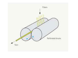
The document discusses wrap spinning and friction spinning systems for yarn production, including descriptions of the wrap spinning and DREF friction spinning processes, their advantages and limitations, end uses of wrap yarns, manufacturers of wrap spinning machines, classifications of friction spinning systems, and features of the DREF-II and DREF-III friction spinning machines.
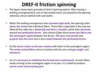
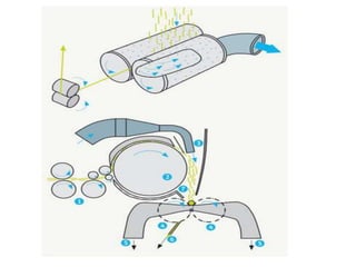
Yarn Engineering Wrap and Friction Spinning Systems
1. MD. MAZBAH UDDIN
BANGLADESH UNIVERSITY OF TEXTILES
YARN ENGINEERING DEPARTMET
BATCH 08
WRAP AND FRICTION SPINNING SYSTEM
2. WRAP SPINNING
1. A roving or sliver feedstock (1) is drafted in a three-, four- or five-roller drafting
arrangement.
2. The fiber strand delivered runs through a hollow spindle (3) without receiving
true twist.
3. In order to impart strength to the strand before it falls apart, a continuous-
filament thread (4) is wound around the strand as it emerges from the drafting
arrangement.
4. The continuous-filament thread comes from a small, rapidly rotating bobbin (5)
mounted on the hollow spindle.
5. Take-off rollers lead the resulting wrap yarn to a winding device.
6. The wrap yarn thus always consists of two components, one twist- free staple-
fiber component in the yarn core (a), and a filament (b) wound around the core.
4. Limitations of Wrap Spinning
1. Only coarser count (50-500 tex) can be spun.
2. Yarn strength depends on binder.
3. Mainly used for long staple.
4. Wrapping structure may be loose due to
washing.
5. Yarn may be wavy if binder is too tight.
Advantages of Wrap Spinning:
1. Less floor space.
2. Spinning directly from sliver.
3. Production rate higher.
4. Sizing is not required.
5. Large package size.
6. Suitable for fancy yarn.
5. End uses of Wrap Spinning:
1. Carpet yarn.
2. Upholstery yarn.
3. Sweater.
4. Blanket.
5. Towel.
6. Outer wear.
Manufacturer of Wrap Spinning:
1. Sussen PL 1000 : For short staple.
2. Sussen PL 2000: For long staple.
3. Mackie
4. Gemmi & Dunsmore (G & D)
5. Saurer Allawa
6. Features of Friction Spinning
1. The main advantage of the friction spinning system is its ability to
generate a number of turns per unit length of yarn with one revolution
of the twisting element.
2. It is possible to spin yarn at a very high production rate up to 300 m/min
due to the low spinning tension required.
3. This system can process a wide range of fibres.
4. It is possible to produce large package, therefore no rewinding is
required.
5. It is also possible to spin core-spun yarns and multi-component yarns
on DREF-III machine.
6. Friction spinning systems have number of limitations which restrict its
acceptance as a viable system for producing general-purpose yarns:
• The main drawback is lower yarn strength. Poor fibre orientation renders
the friction spun yarns relatively weak.
• The extent of disorientation and buckling is greater with longer and finer
fibres.
7. Features of Friction Spinning
• The twist variation from surface to core is
quite high. This is another reason for the low
strength of friction-spun yarns.
• The count range is limited and it is not
possible to produce fine yarn.
• Friction spun yarns have a higher tendency to
snarl.
• Yarns unevenness and imperfections also
increase as production speed increases.
8. Friction Spinning
• Friction spinning was first developed when Fehrer produced the DREF
friction spinning system in 1973. In this machine, the pre-opened fibres
were made to fall onto a perforated cylindrical drum, the rotation of
which imparted twist to the fibre assembly. Due to problems in
controlling the flow, slippage occurred between the fibre assembly and
the perforated roller, which reduced the twist efficiency.
• This process belongs to open end spinning group. Here, the fiber
strand(D/F slivers) is opened to individual fibers and then reassembled
into new strand.
• The formation of this new strand is carried out by using suction to bring
the individual fibers into engagement with the rotating open end of the
yarn( by perforated drums). Binding in of fibers, and imparting strength ,
are effected by continual rotation of the yarn in the converging region of
two drums. The rotation of yarn arises from the rotary movement of
drums and is generated by frictional contact at the drum surfaces. The
yarn formed in the convergent region by collecting and binding in the
fibers must be withdrawn and wound to a cross wound package.
9.
10. Basic operations in friction spinning
1. Opening the fiber strand.
2. Collecting fibers into a new strand.
3. Imparting strength by twisting.
4. Withdrawing the resulting yarn.
5. Winding to a cross wound package.
11. Classification of friction spinning system
• According to feed:
1. Single sliver feed
2. Multiple sliver feed( dref-2, dref-3)
• According to opening assembly:
1. One opening assembly
2. Two opening assemblies or drafting
devices(dref-3)
• According to collection and friction
assemblies:
1. Collection and friction assembly
separated.
2. Friction assembly acts as collection
device.
• No. of friction surfaces:
1. One friction surface.
2. Two friction surface.
• According to types of friction
assembly:
1. Perforated drums.
2. One perforated and one
smooth(blind drum)
3. Two discs.
4. Disc and roller combination
5. Two crossed belts.
Widely used types:
1. Single sliver feed
2. One opener
3. Friction assembly also acts as
collection device.
4. Two friction surface
5. Two perforated drums or one
perforated –one blind.
12. Advantages and disadvantages
ADVANTAGES ARE AS FOLLOWS:
• high delivery speeds;
• low yarn production costs (lower than those of ring spinning);
• elimination of rewinding;
• low end breakage rates;
• yarn character similar to that of ring-spun yarn;
• no wrapping fibers;
• optically good mass evenness (well suited to knitted goods);
• better and softer handle than that of rotor-spun yarn;
• smooth yarn appearance.
DISADVANTAGES ARE:
• low yarn strength;
• high tendency to snarl;
• higher number of fibers needed in yarn cross-section;
• difficulty of keeping spinning conditions constant;
• high air consumption;
• Increasing unevenness and imperfections with increasing spinning speed, and further
reduction in yarn strength
13. DREF-II friction spinning
• The figure shows basic principle of dref-2 spinning system. After leaving a
drafting arrangement(1), one or two carded slivers are passed to the opening
roller(2)( a drum clothed with saw tooth).
• While The drafting arrangement here provides light draft, the opening roller
opens the strand into individual fibers. These fibers separated in this way are
lifted off the roller by a blower(3) and form a cloud(7), which then descends
toward two perforated drums . One stream (5)per drum draws the fibers into
the convergent region between the drums. The open end yarn(6) also
projects into this zone and is also sucked towards the perforated drums.
• As the drums rotate so the yarn rotates with them in the convergent region.
The newly arrived fibers come in contact with the yarn and get caught and
twisted in.
• So, it is necessary to withdraw the formed yarn continuously to twist fibers
newly arriving in the convergent region in to yarn. It is suited to produce
coarse count and recycling yarn.
14.
15. DREF-III friction spinning
The DREF-III friction spinning machine was
introduced into the market in 1981. This
machine was developed to improve yarn
quality, extend the yarn count up to 18s Ne and
produce multi-component yarns. The DREF-III
uses a core-sheath type friction arrangement as
shown in Figure 2. In this machine an attempt
was made to improve the quality of yarn by
aligning the majority of fibres in the direction
of yarn axis.
16. DREF-III friction spinning
• Dref-3 produces bundled yarn according to friction spinning principle. Its an expansion of
dref-2 to accommodate a drafting arrangement before the spinning drums.
• A D/F(2.5-3.5 ktex) sliver is passed into a double apron roller drafting arrangement( 3
drafting zones). The drafted strand ( 100-150 draft) delivered is passed towards the
convergent region of two perforated drums. A pair of withdrawal rollers draws the this
strand through perforated drums and out of the spinning zone. So, it is apparent that the
coherent fiber strand is nipped between withdrawal rollers and the drafting arrangement,
and is rotating between these two points by the perforated drums . Hence, it’s a false
twisted between these points. Meaning that turns are present between the drafting and
the perforated drums not between perforated drums and withdrawal rollers.
• If this is continued , the strand will fall apart. So before this happens, staple fibers are fed
from above on to the convergent region. Due to the rotation of perforated drums these
staple fibers wrap themselves around the horizontally moving strand. Thus a bundled yarn
is formed.
• These staple fibers are coming from a another drafting arrangement with two opening
rollers. The feed to this drafting arrangement is 4-6 D/F slivers (2,5-3,5ktex).
The produced yarn is then withdrawn and wound onto cross wound package.