Downloaded 250 times
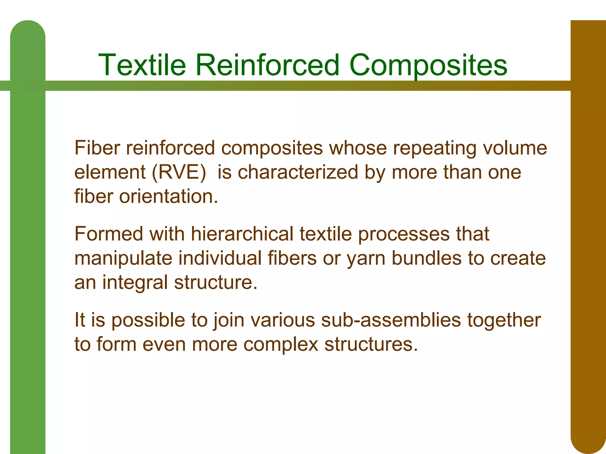
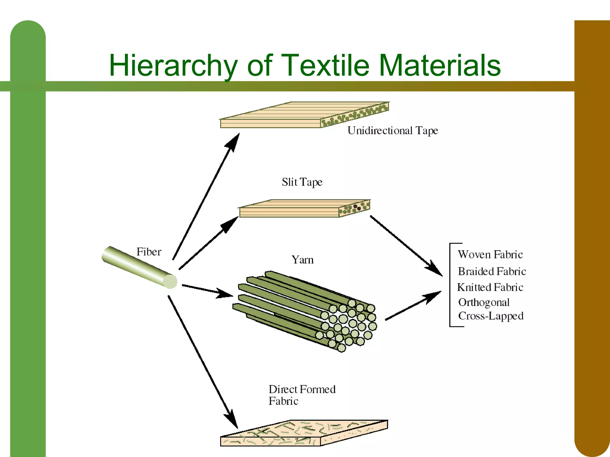

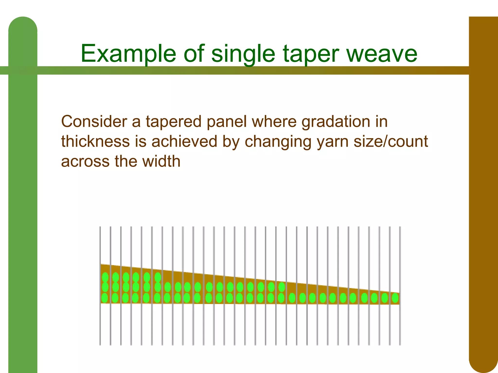
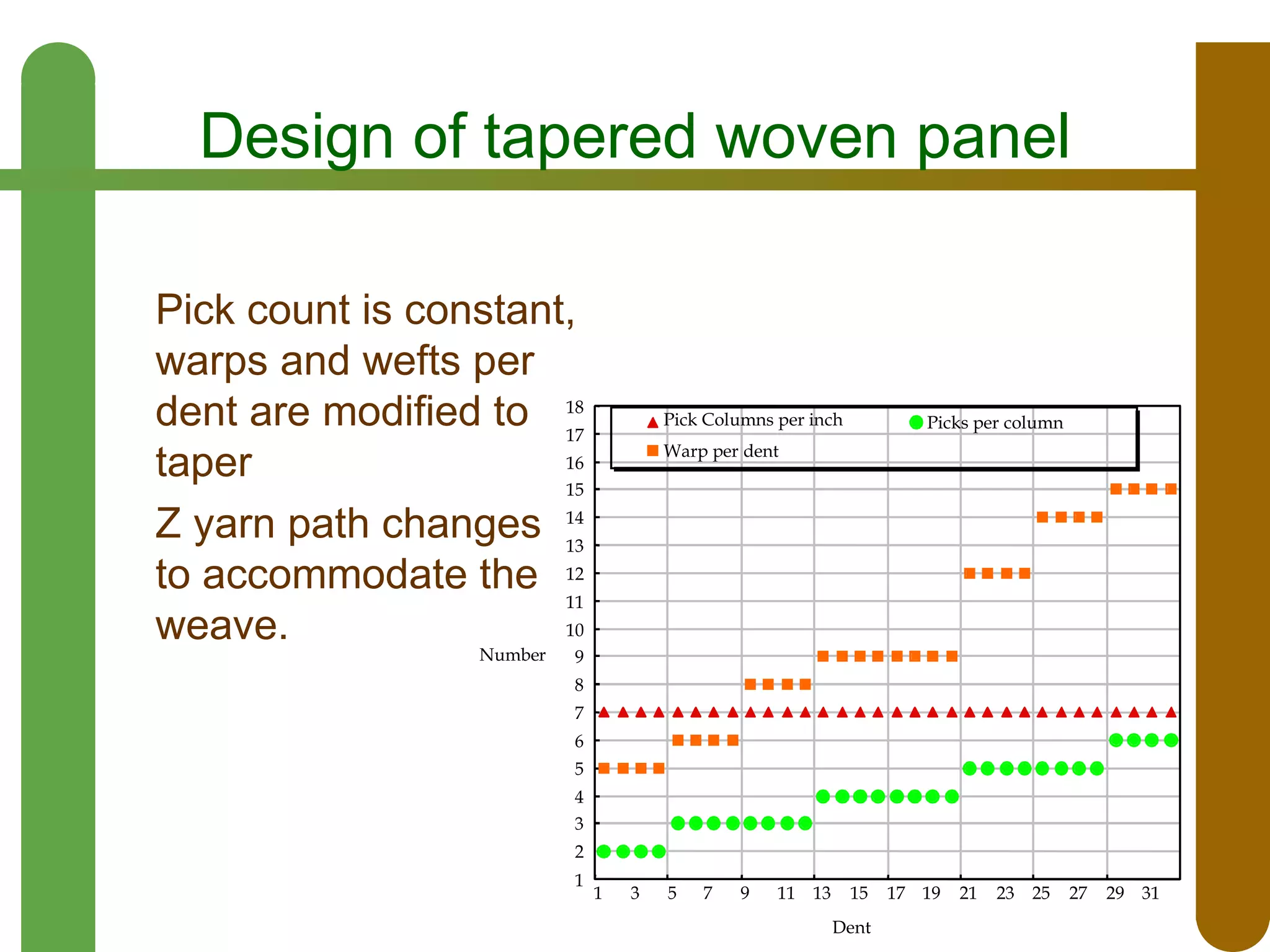

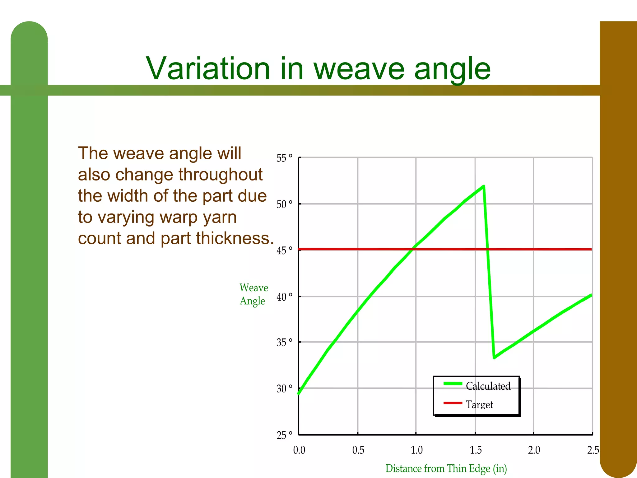
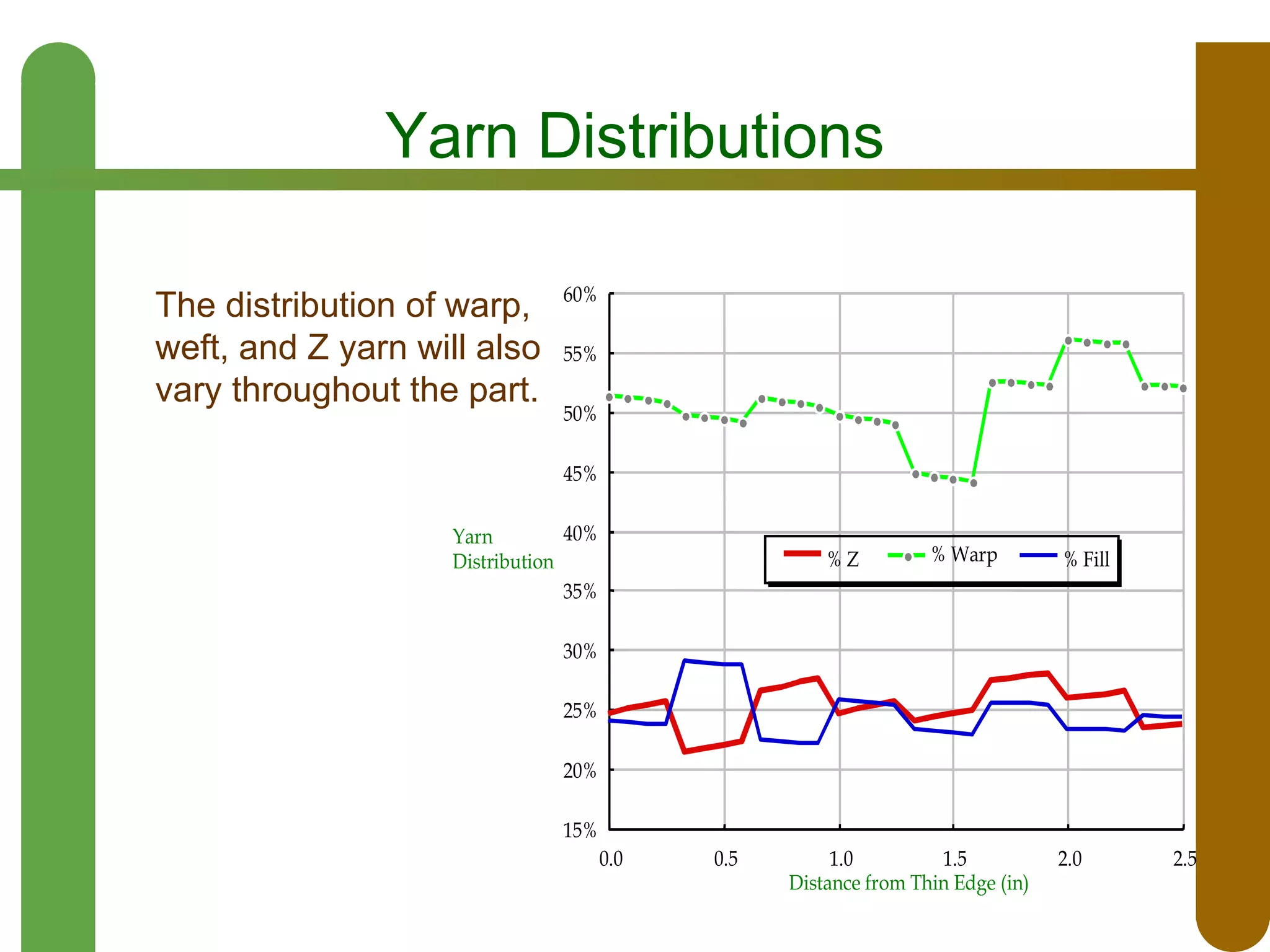
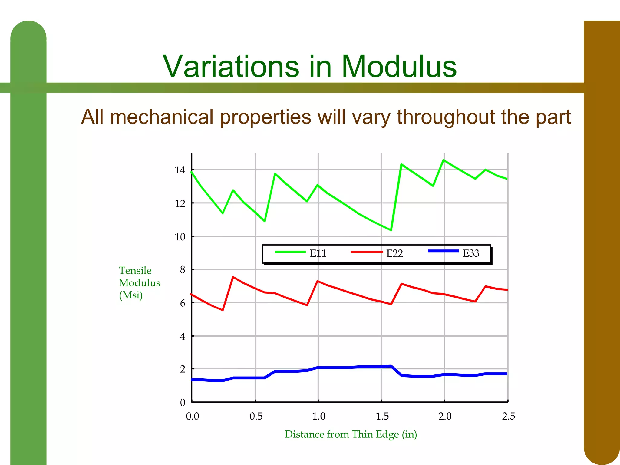

This document discusses opportunities and challenges for textile reinforced composites. It describes how textiles can be formed using various processes like weaving, knitting, braiding, and direct forming to create structures with multiple fiber orientations. Textiles are considered to have cost advantages over tape layup methods. However, shaping textiles to create tapered or complex geometries can introduce variations in fiber volume fraction, weave angle, yarn distribution, and mechanical properties across the structure. Careful design is required to minimize these variations.


![Polymer matrix composites [pmc]](https://cdn.slidesharecdn.com/ss_thumbnails/polymermatrixcomposites-110526080726-phpapp01-160103174810-thumbnail.jpg?width=640&height=640&fit=bounds)