
Download as PDF, PPTX

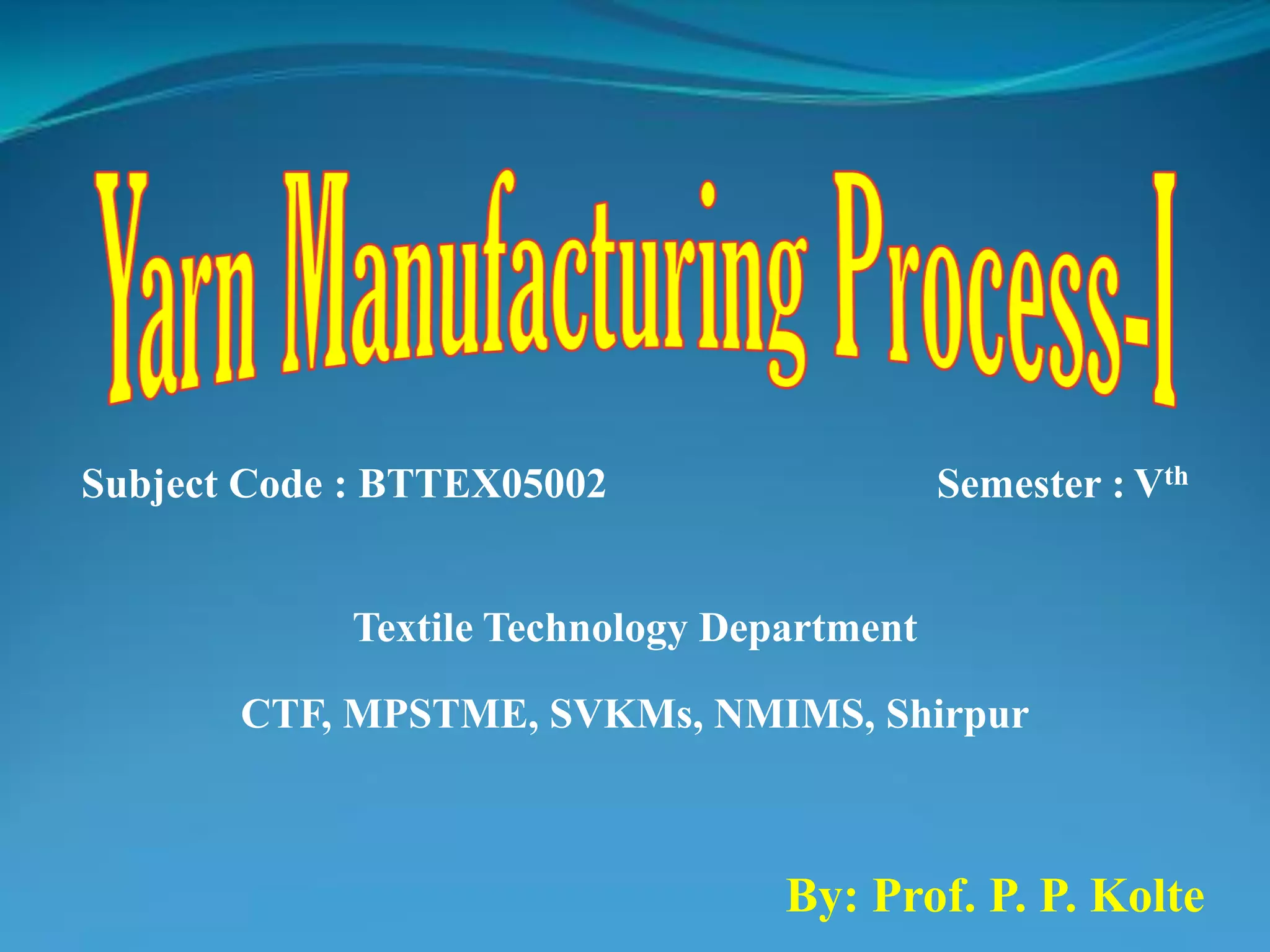


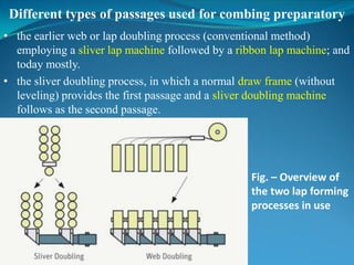
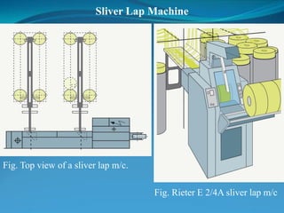
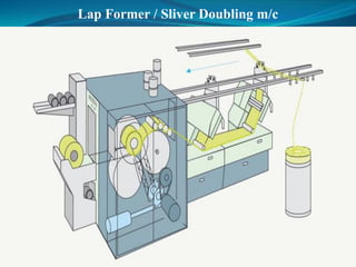
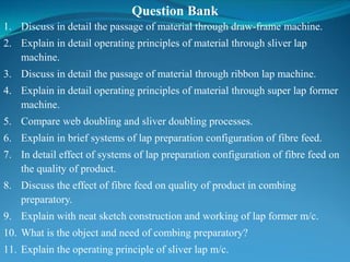
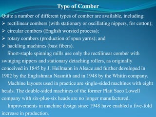
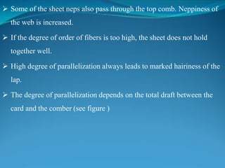
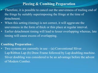
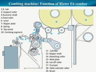
![- 4/5 drafting system
- drafting capacity 10, generally working draft 8.
- Three sliver creel with stand, each has capacity 20 and are double
sided. Hence, 60 doublings possible.
- Maximum total draft of 3.75 with 60 doubling.
- Lap weight 1200 grains/yard [85 gms/m]
- Production rate 250-290 Kg/hr
Fig. Sliver feeding at super lap former](https://image.slidesharecdn.com/comber-180912060236/85/Yarn-Manufacturing-Process-Comber-Part-I-21-320.jpg)
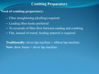
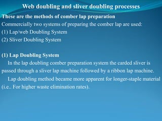
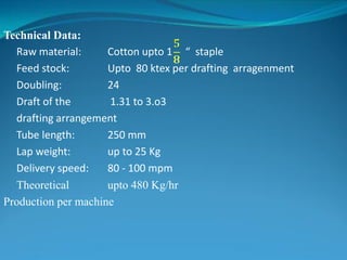
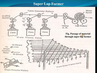
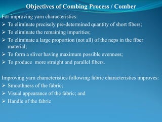
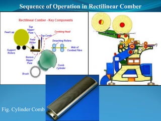
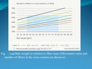
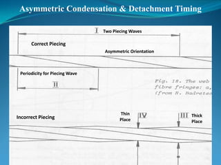
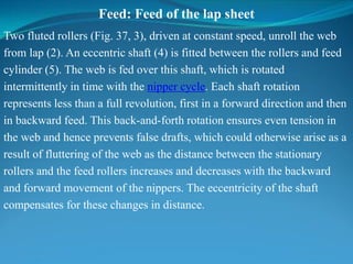
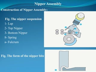
![Preparation of stock for combing
[System of lap preparation configuration of fibre feed and its effect on
the quality of product]
Fig. – Clamped slivers between
the nipper plates
Fig. – Fibers projecting from
the nippers](https://image.slidesharecdn.com/comber-180912060236/85/Yarn-Manufacturing-Process-Comber-Part-I-22-320.jpg)


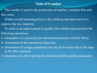
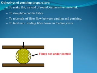
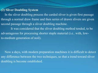
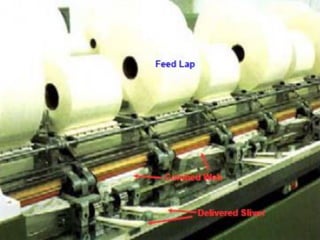
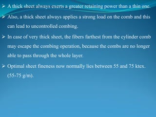
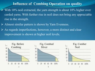
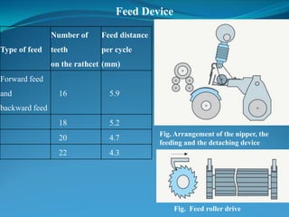
![Types of Application
The amount of material combed out varies within the range between
8% and 25% of the infeed stock.
1] For Long Staple combing mills:
Processing first-class, expensive cotton of high strength,
containing a low proportion of short fibers and little dirt.
The product is a fine to very fine yarn of top quality.
The demands placed on know-how and skill of operating personnel
is correspondingly high, as they are on the design
and maintenance of the machines.
Yarn production is low, while generation of noil is high.](https://image.slidesharecdn.com/comber-180912060236/85/Yarn-Manufacturing-Process-Comber-Part-I-31-320.jpg)
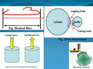
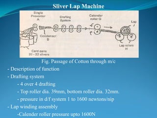
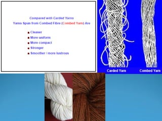
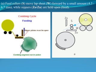
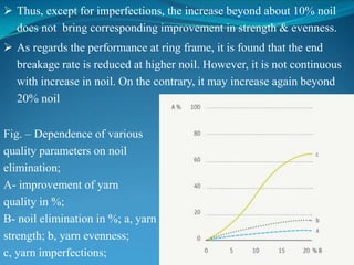
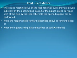
![2] For Medium-staple combing mills:
Medium cotton qualities with a wide spread of quality parameters are
spun into medium (to fine) yarns of good quality at economic production
costs.
The process is problematic in that it has to achieve a high strand of
quality and at the same time give high production at low cost.
The maximum demands placed on medium staple combing can only
be fulfilled by optimally trained personnel.
3] Short to Medium staple combing mills:
Raw material used have the same as that for production of carded
yarns.
In this combination with low level noil level (6 – 14%).
This process is the most widely used in practice; it is technologically
undemanding and can be operated without problems when good m/c
are available.](https://image.slidesharecdn.com/comber-180912060236/85/Yarn-Manufacturing-Process-Comber-Part-I-32-320.jpg)
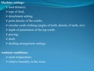
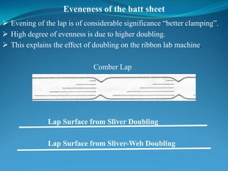
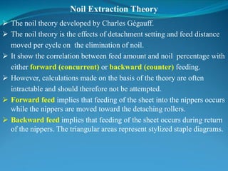
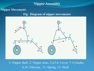
![Influences of the feed stock on combing
1. Parallalisation of the fibres in the batt / lap
2. Batt / lap Thickness[Weight]
3. Eveneness of the batt / lap sheet
4. The disposition of the hooks](https://image.slidesharecdn.com/comber-180912060236/85/Yarn-Manufacturing-Process-Comber-Part-I-50-320.jpg)
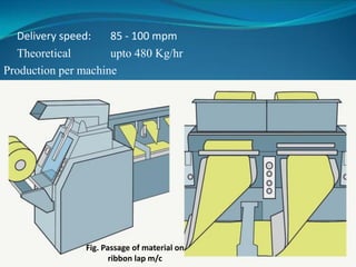
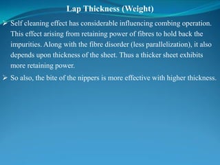
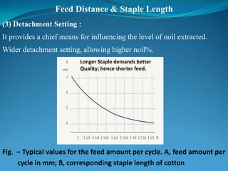
![Lap / Batt Thickness[Weight]
Fig. – Batt weight in relation to staple length](https://image.slidesharecdn.com/comber-180912060236/85/Yarn-Manufacturing-Process-Comber-Part-I-55-320.jpg)
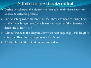
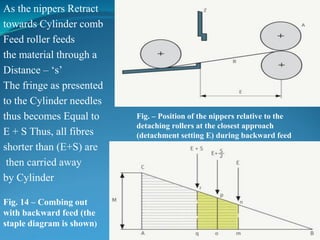
![Derivation of Gegauff’s expression:
• The ‘po’ is dividing line representing a length (E+s/2). Further, in
similar triangles, the ratio of the areas are proportional to squares of
the sides, and as the areas represents the noil percentage based on the
ratio of weight of noil to that of feed stock, following can be stated :
∆opB (op)2
• Noil (p%) = ------ x 100 = ------- x 100
∆ABC (AC)2
= [ E + s/2]2 / M2 x 100](https://image.slidesharecdn.com/comber-180912060236/85/Yarn-Manufacturing-Process-Comber-Part-I-70-320.jpg)
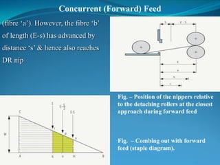
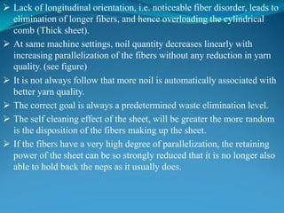
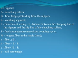
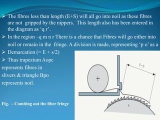
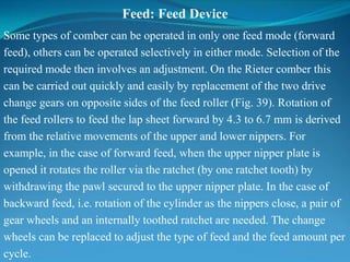
![Concurrent (Forward) Feed
Fibre ‘C’, still shorter than distance (E-S), thus will not be able to
reach the detaching roller nip.
With earlier logic the diagram (fig. ), gives three lines representing –
‘E’, ‘E-S/2’ and ‘E-S’ lines.
Thus, percentage of noil will be –
Noil% = [ ∆(opB) / ∆(ABC)] x 100
= [ (op)2 / AC2] x 100
= [E – (S/2)2 / M2] x 100 (Forward feed)
and [E+ (S/2)2 / M2] x 100 (Backward feed)
From the two derived expressions, it follows that in Counter
(Backward) Feed, the noil level is increased as the feed distance is
raised. Whereas, in the Concurrent (Forward) Feed, the noil is
reduced.](https://image.slidesharecdn.com/comber-180912060236/85/Yarn-Manufacturing-Process-Comber-Part-I-73-320.jpg)


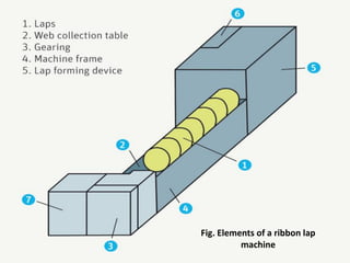
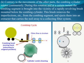
The document discusses combing preparatory processes. It describes the need for combing preparatory, which includes fiber straightening, reversing fiber flow, and producing a flat sliver. Traditionally, this involved a sliver lap machine and ribbon lap machine, but now mostly uses a draw frame and sliver lap machine. The objectives of combing preparatory are to straighten fibers, reverse flow, maximize leading fiber hooks, and produce a flat sliver. Different machine types and their functions are explained, including parameters that influence the combing operation and quality of the finished product.


![Yarn Manufacturing Process : Comber Part II [Modern combers]](https://cdn.slidesharecdn.com/ss_thumbnails/moderncombers-180912060904-thumbnail.jpg?width=640&height=640&fit=bounds)


![Spinning [compatibility mode],Yarn types classification](https://cdn.slidesharecdn.com/ss_thumbnails/spinningcompatibilitymode-151215095342-thumbnail.jpg?width=640&height=640&fit=bounds)


