Downloaded 15 times


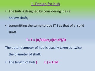


![• Direct shear stress due to pure torsion in the
coupling halve
• τ=W/[ (π/4) (d 1 )]
2
• maximum bending moment on the pin
• M =W (l/2 +5mm)
• bending stress
σ= M / Z
= W (l/2 +5mm)/ (π/32) (d 1
3)](https://image.slidesharecdn.com/11ccouplings-flangecoupling-210302065547/85/11-c-couplings-flange-coupling-23-320.jpg)
![• Maximum principal stress
= 1/2[σ +(σ+4τ2 )1/2]
• maximum shear stress on the pin
= 1/2(σ+4τ2 )1/2
• The value of maximum principal stress varies
from 28 to 42 MPa](https://image.slidesharecdn.com/11ccouplings-flangecoupling-210302065547/85/11-c-couplings-flange-coupling-24-320.jpg)

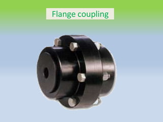
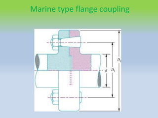
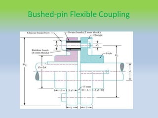
This document describes different types of flange couplings, including their design and components. It discusses unprotected, protected, and marine type flange couplings. It also covers the design of a bushed-pin flexible coupling, which is a modification of the rigid flange coupling that uses rubber or leather bushes over the coupling pins to allow some flexibility. Key aspects covered include hub, key, flange, bolt, and pin/bush designs and specifications.


