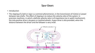
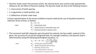
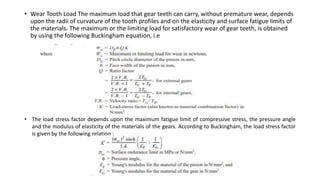
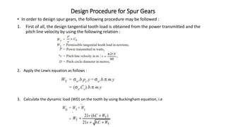
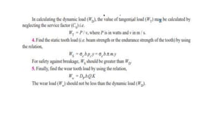
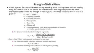
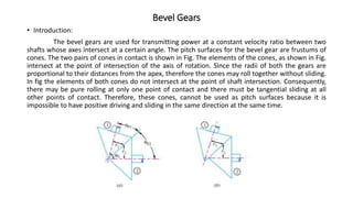
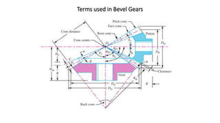
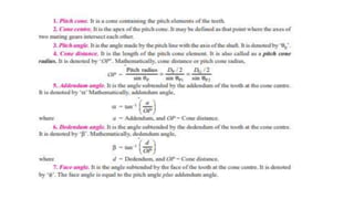
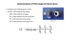
SlideShare a Scribd company logo
1 of 46
Introduction to
Gears
SARDAR PATEL COLLEGE OF ENGINEERING – BAKROL
PROF. HEENA K SHARMA
Spur Gears
• Introduction
• The slipping of a belt or rope is a common phenomenon, in the transmission of motion or power
between two shafts. The effect of slipping is to reduce the velocity ratio of the system. In
precision machines, in which a definite velocity ratio is of importance (as in watch mechanism),
the only positive drive is by gears or toothed wheels. A gear drive is also provided, when the
distance between the driver and the follower is very small.
Advantages and Disadvantages of Gear Drives
• The following are the advantages and disadvantages of the gear drive as compared to other
drives, i.e. belt, rope and chain drives : Advantages
• 1. It transmits exact velocity ratio.
• 2. It may be used to transmit large power.
• 3. It may be used for small centre distances of shafts.
• 4. It has high efficiency.
• 5. It has reliable service.
• 6. It has compact layout.
Disadvantages
• 1. Since the manufacture of gears require special tools and equipment, therefore it is costlier than
other drives.
• 2. The error in cutting teeth may cause vibrations and noise during operation.
• 3. It requires suitable lubricant and reliable method of applying it, for the proper operation of
gear drives.
Terms used in Gears
1. Pitch circle. It is an imaginary circle which by pure rolling action, would give the same motion as the
actual gear.
2. Pitch circle diameter. It is the diameter of the pitch circle. The size of the gear is usually specified by the
pitch circle diameter. It is also called as pitch diameter.
3. Pitch point. It is a common point of contact between two pitch circles.
4. Pitch surface. It is the surface of the rolling discs which the meshing gears have replaced at the pitch
circle.
5. Pressure angle or angle of obliquity. It is the angle between the common normal to two gear teeth at the
point of contact and the common tangent at the pitch point. It is usually denoted by φ. The standard
pressure angles are 1 14 /2° and 20°.
6. Addendum. It is the radial distance of a tooth from the pitch circle to the top of the tooth.
7. Dedendum. It is the radial distance of a tooth from the pitch circle to the bottom of the tooth.
8. Addendum circle. It is the circle drawn through the top of the teeth and is concentric with the pitch circle.
9. Dedendum circle. It is the circle drawn through the bottom of the teeth. It is also called root circle. Note :
Root circle diameter = Pitch circle diameter × cos φ, where φ is the pressure angle.
10. Circular pitch. It is the distance measured on the circumference of the pitch circle from a point of one
tooth to the corresponding point on the next tooth. It is usually denoted by pc . Mathematically,
Circular pitch, pc = π D/T
where D = Diameter of the pitch circle, and T = Number of teeth on the wheel.
11. Diametral pitch. It is the ratio of number of teeth to the pitch circle diameter in millimetres. It
denoted by pd. Mathematically
Diametral pitch, pd = c T/ D = π/PC
where T = Number of teeth, and D = Pitch circle diameter
12. Module. It is the ratio of the pitch circle diameter in millimetres to the number of teeth. It is
usually denoted by m.
Mathematically, Module, m = D / T
13. Clearance. It is the radial distance from the top of the tooth to the bottom of the tooth, in a
meshing gear. A circle passing through the top of the meshing gear is known as clearance circle.
14. Total depth. It is the radial distance between the addendum and the dedendum circle of a gear.
It is equal to the sum of the addendum and dedendum.
15. Working depth. It is radial distance from the addendum circle to the clearance circle. It is equal
to the sum of the addendum of the two meshing gears.
16. Tooth thickness. It is the width of the tooth measured along the pitch circle.
17. Tooth space. It is the width of space between the two adjacent teeth measured along the pitch
circle
18. Backlash. It is the difference between the tooth space and the tooth thickness, as measured on
the pitch circle.
19. Face of the tooth. It is surface of the tooth above the pitch surface.
20. Top land. It is the surface of the top of the tooth.
21. Flank of the tooth. It is the surface of the tooth below the pitch surface.
22. Face width. It is the width of the gear tooth measured parallel to its axis.
23. Profile. It is the curve formed by the face and flank of the tooth.
24. Fillet radius. It is the radius that connects the root circle to the profile of the tooth.
25. Path of contact. It is the path traced by the point of contact of two teeth from the
beginning to the end of engagement.
26. Length of the path of contact. It is the length of the common normal cut-off by the
addendum circles of the wheel and pinion.
27. Arc of contact. It is the path traced by a point on the pitch circle from the beginning to
the end of engagement of a given pair of teeth. The arc of contact consists of two
parts, i.e. (a) Arc of approach. It is the portion of the path of contact from the
beginning of the engagement to the pitch point. (b) Arc of recess. It is the portion of
the path of contact from the pitch point to the end of the engagement of a pair of
teeth.
Condition for Constant Velocity Ratio of Gears–Law of Gearing
• Consider the portions of the two teeth, one on the wheel 1 (or pinion) and the other on the
wheel 2, as shown by thick line curves in Fig. Let the two teeth come in contact at point Q, and
the wheels rotate in the directions as shown in the figure.
• Let T T be the common tangent and MN be the common normal to the curves at point of contact
Q. From the centres O1 and O2, draw O1M and O2N perpendicular to MN. A little consideration
will show that the point Q moves in the direction QC, when considered as a point on wheel 1, and
in the direction QD when considered as a point on wheel 2.
• Let v1 and v2 be the velocities of the point Q on the wheels 1 and 2 respectively. If the teeth are
to remain in contact, then the components of these velocities along the common normal MN
must be equal.
Therefore, in order to have a constant angular velocity ratio for all positions of the wheels, P must be the fixed
point (called pitch point) for the two wheels. In other words, the common normal at the point of contact between
a pair of teeth must always pass through the pitch point. This is fundamental condition which must be satisfied
while designing the profiles for the teeth of gear wheels. It is also known as law of gearing.
• Forms of Teeth:We have discussed in that conjugate teeth are not in common use. Therefore, in
actual practice, following are the two types of teeth commonly used.
1. Cycloidal teeth ;
2. Involute teeth.
We shall discuss both the above mentioned types of teeth in the following articles.
• Cycloidal Teeth:
A cycloid is the curve traced by a point on the circumference of a circle which rolls without
slipping on a fixed straight line. When a circle rolls without slipping on the outside of a fixed circle,
the curve traced by a point on the circumference of a circle is known as epicycloid. On the other
hand, if a circle rolls without slipping on the inside of a fixed circle, then the curve traced by a point
on the circumference of a circle is called hypocycloid.
• Involute Teeth :An involute of a circle is a plane curve generated by a point on a tangent, which
rolls on the circle without slipping or by a point on a taut string which is unwrapped from a reel as
shown in Fig. In connection with toothed wheels, the circle is known as base circle.
Design Considerations for a Gear Drive
• In the design of a gear drive, the following data is usually given :
• 1. The power to be transmitted.
• 2. The speed of the driving gear,
• 3. The speed of the driven gear or the velocity ratio, and
• 4. The centre distance.
The following requirements must be met in the design of a gear drive :
(a) The gear teeth should have sufficient strength so that they will not fail under static loading or
dynamic loading during normal running conditions.
(b) The gear teeth should have wear characteristics so that their life is satisfactory.
(c) The use of space and material should be economical.
(d) The alignment of the gears and deflections of the shafts must be considered because they
effect on the performance of the gears.
(e) The lubrication of the gears must be satisfactory
Beam Strength of Gear Teeth – Lewis Equation
• The beam strength of gear teeth is determined from an equation
(known as *Lewis equation) and the load carrying ability of the
toothed gears as determined by this equation gives satisfactory
results. In the investigation, Lewis assumed that as the load is being
transmitted from one gear to another, it is all given and taken by one
tooth, because it is not always safe to assume that the load is
distributed among several teeth.
• When contact begins, the load is assumed to be at the end of the
driven teeth and as contact ceases, it is at the end of the driving
teeth. This may not be true when the number of teeth in a pair of
mating gears is large, because the load may be distributed among
several teeth. But it is almost certain that at some time during the
contact of teeth, the proper distribution of load does not exist and
that one tooth must transmit the full load. In any pair of gears
having unlike number of teeth, the gear which have the fewer teeth
(i.e. pinion) will be the weaker, because the tendency toward
undercutting of the teeth becomes more pronounced in gears as the
number of teeth becomes smaller
• therefore, conclude that the section BC is the section of maximum stress or the critical section.
The maximum value of the bending stress (or the permissible working stress), at the section BC is
given by
Permissible Working Stress for Gear Teeth in the Lewis Equation
• The permissible working stress (σw) in the Lewis equation depends upon the material for which
an allowable static stress (σo) may be determined. The allowable static stress is the stress at
theelastic limit of the material. It is also called the basic stress. In order to account for the
dynamic effects which become more severe as the pitch line velocity increases, the value of σw is
reduced. According to the Barth formula, the permissible working stress,
• Dynamic Tooth Load In the previous article, the velocity factor was used to make approximate
allowance for the effect of dynamic loading. The dynamic loads are due to the following reasons :
• 1. Inaccuracies of tooth spacing,
• 2. Irregularities in tooth profiles, and
• 3. Deflections of teeth under load.
A closer approximation to the actual conditions may be made by the use of equations based on
extensive series of tests, as follows :
• The increment load (WI ) depends upon the pitch line velocity, the face width, material of the
gears, the accuracy of cut and the tangential load. For average conditions, the dynamic load is
determined by using the following Buckingham equation, i.e.
• Wear Tooth Load The maximum load that gear teeth can carry, without premature wear, depends
upon the radii of curvature of the tooth profiles and on the elasticity and surface fatigue limits of
the materials. The maximum or the limiting load for satisfactory wear of gear teeth, is obtained
by using the following Buckingham equation, i.e
• The load stress factor depends upon the maximum fatigue limit of compressive stress, the pressure angle
and the modulus of elasticity of the materials of the gears. According to Buckingham, the load stress factor
is given by the following relation :
Design Procedure for Spur Gears
• In order to design spur gears, the following procedure may be followed :
1. First of all, the design tangential tooth load is obtained from the power transmitted and the
pitch line velocity by using the following relation :
2. Apply the Lewis equation as follows :
3. Calculate the dynamic load (WD) on the tooth by using Buckingham equation, i.e
Design of Shaft for Spur Gears
Helical Gears
• Introduction:
A helical gear has teeth in form of helix around the gear. Two such gears may be
used to connect two parallel shafts in place of spur gears. The helixes may be right handed on one
gear and left handed on the other. The pitch surfaces are cylindrical as in spur gearing, but the teeth
instead of being parallel to the axis, wind around the cylinders helically like screw threads. The teeth
of helical gears with parallel axis have line contact, as in spur gearing. This provides gradual
engagement and continuous contact of the engaging teeth. Hence helical gears give smooth drive with
a high efficiency of transmission.
• Terms used in Helical Gears:
• The following terms in connection with helical gears, are important from the subject point of view.
1. Helix angle. It is a constant angle made by the helices with the axis of rotation.
2. Axial pitch. It is the distance, parallel to the axis, between similar faces of adjacent teeth. It is the
same as circular pitch and is therefore denoted by pc . The axial pitch may also be defined as the
circular pitch in the plane of rotation or the diametral plane.
3. Normal pitch. It is the distance between similar faces of adjacent teeth along a helix on the pitch
cylinders normal to the teeth. It is denoted by pN. The normal pitch may also be defined as the
circular pitch in the normal plane which is a plane perpendicular to the teeth. Mathematically, normal
pitch, pN = pc cos α
• Face Width of Helical Gears:
In order to have more than one pair of teeth in contact, the tooth displacement
(i.e. the advancement of one end of tooth over the other end) or overlap should be at least equal to
the axial pitch, such that
Overlap = pc = b tan α ...(i)
The normal tooth load (WN) has two components ; one is tangential component (WT) and
the other axial component (WA),
The axial or end thrust is given by
WA = WN sin α = WT tan α ...(ii)
From equation (i), we see that as the helix angle increases, then the tooth overlap increases. But at
the same time, the end thrust as given by equation (ii), also increases, which is undesirable. It is
usually recommended that the overlap should be 15 percent of the circular pitch.
• The formative or equivalent number of teeth for a helical gear may be defined as the number of teeth
that can be generated on the surface of a cylinder having a radius equal to the radius of curvature at a
point at the tip of the minor axis of an ellipse obtained by taking a section of the gear in the normal
plane. Mathematically, formative or equivalent number of teeth on a helical gear,
TE = T / cos3 α
where T = Actual number of teeth on a helical gear, and α = Helix angle.
• Proportions for Helical Gears Though the proportions for helical gears are not standardised, yet the
following are recommended by American Gear Manufacturer's Association (AGMA).
• Pressure angle in the plane of rotation, φ = 15° to 25°
• Helix angle, α = 20° to 45°
• Addendum = 0.8 m (Maximum)
• Dedendum = 1 m (Minimum)
• Minimum total depth = 1.8 m
• Minimum clearance = 0.2 m
• Thickness of tooth = 1.5708 m
Formative or Equivalent Number of Teeth for Helical Gears
Strength of Helical Gears
• In helical gears, the contact between mating teeth is gradual, starting at one end and moving
along the teeth so that at any instant the line of contact runs diagonally across the teeth.
Therefore in order to find the strength of helical gears, a modified Lewis equation is used. It is
given by
Bevel Gears
• Introduction:
The bevel gears are used for transmitting power at a constant velocity ratio between two
shafts whose axes intersect at a certain angle. The pitch surfaces for the bevel gear are frustums of
cones. The two pairs of cones in contact is shown in Fig. The elements of the cones, as shown in Fig.
intersect at the point of intersection of the axis of rotation. Since the radii of both the gears are
proportional to their distances from the apex, therefore the cones may roll together without sliding.
In fig the elements of both cones do not intersect at the point of shaft intersection. Consequently,
there may be pure rolling at only one point of contact and there must be tangential sliding at all
other points of contact. Therefore, these cones, cannot be used as pitch surfaces because it is
impossible to have positive driving and sliding in the same direction at the same time.
Terms used in Bevel Gears
Determination of Pitch Angle for Bevel Gears
• Consider a pair of bevel gears in mesh,
• Let θP1 = Pitch angle for the pinion,
θP2 = Pitch angle for the gear,
θS = Angle between the two shaft axes,
DP = Pitch diameter of the pinion,
DG = Pitch diameter of the gear, and
Formative or Equivalent Number of Teeth for Bevel Gears – Tredgold’s
Approximation
• A similar analysis for a bevel gear will show that a true section of the resulting involute lies on the
surface of a sphere. But it is not possible to represent on a plane surface the exact profile of a
bevel gear tooth lying on the surface of a sphere. Therefore, it is important to approximate the
bevel gear tooth profiles as accurately as possible. The approximation (known as Tredgold’s
approximation) is based upon the fact that a cone tangent to the sphere at the pitch point will
closely approximate the surface of the sphere for a short distance either side of the pitch point,
Strength of Bevel Gears
• The strength of a bevel gear tooth is obtained in a similar way as discussed in the previous
articles. The modified form of the Lewis equation for the tangential tooth load is given as follows:
Forces Acting on a Bevel Gear
• Consider a bevel gear and pinion in mesh as shown in Fig. The normal force (WN) on the tooth is
perpendicular to the tooth profile and thus makes an angle equal to the pressure angle (φ) to the
pitch circle. Thus normal force can be resolved into two components, one is the tangential
component (WT) and the other is the radial component (WR). The tangential component (i.e. the
tangential tooth load) produces the bearing reactions while the radial component produces end
thrust in the shafts. The magnitude of the tangential and radial components is as follows :
WT = WN cos φ, and WR = WN sin φ = WT tan φ
• axial force acting on the pinion shaft,
• and the radial force acting on the pinion shaft,
Design of a Shaft for Bevel Gears
Worm Gears
• Introduction
• The worm gears are widely used for transmitting power at high velocity ratios between non-
intersecting shafts that are generally, but not necessarily, at right angles. It can give velocity ratios
as high as 300 : 1 or more in a single step in a minimum of space, but it has a lower efficiency. The
worm gearing is mostly used as a speed reducer, which consists of worm and a worm wheel or
gear. The worm (which is the driving member) is usually of a cylindrical form having threads of the
same shape as that of an involute rack.
• The threads of the worm may be left handed or right handed and single or multiple threads. The
worm wheel or gear (which is the driven member) is similar to a helical gear with a face curved to
conform to the shape of the worm. The worm is generally made of steel while the worm gear is
made of bronze or cast iron for light service.
• The worm gearing is classified as non-interchangeable, because a worm wheel cut with a hob of
one diameter will not operate satisfactorily with a worm of different diameter, even if the thread
pitch is same.
Types of Worms
• The following are the two types of worms :
1. Cylindrical or straight worm, and
2. Cone or double enveloping worm.
The cylindrical or straight worm, as shown in Fig. (a), is most commonly used. The shape of
the thread is involute helicoid of pressure angle 14 ½° for single and double threaded worms and
20° for triple and quadruple threaded worms. The worm threads are cut by a straight sided milling
cutter having its diameter not less than the outside diameter of worm or greater than 1.25 times
the outside diameter of worm. The cone or double enveloping worm, as shown in Fig. (b), is used to
some extent, but it requires extremely accurate alignment.
Terms used in Worm Gearing
1. Axial pitch. It is also known as linear pitch of a worm. It is the distance measured axially (i.e.
parallel to the axis of worm) from a point on one thread to the corresponding point on the
adjacent thread on the worm, as shown in above Fig. It may be noted that the axial pitch (pa) of
a worm is equal to the circular pitch ( pc ) of the mating worm gear, when the shafts are at right
angles.
2. Lead. It is the linear distance through which a point on a thread moves ahead in one revolution
of the worm. For single start threads, lead is equal to the axial pitch, but for multiple start
threads, lead is equal to the product of axial pitch and number of starts. Mathematically,
Lead, l = pa . n
where pa = Axial pitch ; and n = Number of starts.
3. Lead angle. It is the angle between the tangent to the thread helix on the pitch cylinder and the
plane normal to the axis of the worm. It is denoted by λ.
4. Tooth pressure angle. It is measured in a plane containing the axis of the worm and is equal to
one-half the thread profile angle.
5. Normal pitch. It is the distance measured along the normal to the threads between two
corresponding points on two adjacent threads of the worm. Mathematically, Normal pitch,
pN = pa.cos λ
6. Helix angle. It is the angle between the tangent to the thread helix on the pitch cylinder and the
axis of the worm. It is denoted by αW, in Fig. 31.3. The worm helix angle is the complement of
worm lead angle, i.e. αW + λ = 90°
It may be noted that the helix angle on the worm is generally quite large and that on the
worm gear is very small. Thus, it is usual to specify the lead angle (λ) on the worm and helix
angle (αG) on the worm gear. These two angles are equal for a 90° shaft angle.
7. Velocity ratio. It is the ratio of the speed of worm (NW) in r.p.m. to the speed of the worm gear
(NG) in r.p.m. Mathematically, velocity ratio,
Efficiency of Worm Gearing
• The efficiency of worm gearing may be defined as the ratio of work done by the worm gear to the
work done by the worm.
Mathematically, the efficiency of worm gearing is given by
• In order to find the approximate value of the efficiency, assuming square threads, the following relation may
be used :
Thermal Rating of Worm Gearing
• In the worm gearing, the heat generated due to the work lost in friction must be dissipated in
order to avoid over heating of the drive and lubricating oil.
• The quantity of heat generated (Qg) is given by
Qg = Power lost in friction in watts = P (1 – η) ...(i)
where P = Power transmitted in watts, and
η = Efficiency of the worm gearing.
• The heat generated must be dissipated through the lubricating oil to the gear box housing and
then to the atmosphere. The heat dissipating capacity depends upon the following factors :
• 1. Area of the housing (A),
• 2. Temperature difference between the housing surface and surrounding air (t 2 – t 1), and 3.
Conductivity of the material (K).
• Mathematically, the heat dissipating capacity,
Qd = A (t 2 – t 1) K ...(ii)
From equations (i) and (ii), we can find the temperature difference (t 2 – t 1). The average
value of K may be taken as 378 W/m2/°C
Forces Acting on Worm Gears
• When the worm gearing is transmitting power, the forces acting on the worm are similar to those
on a power screw. Fig. shows the forces acting on the worm. It may be noted that the forces on a
worm gear are equal in magnitude to that of worm, but opposite in direction to those shown in
Fig.
Gear design

More Related Content

What's hot (20)

Fundamental and selection of bearings
Fundamental and selection of bearingsFundamental and selection of bearings
Fundamental and selection of bearings
 
Gear trains
Gear trainsGear trains
Gear trains
 
Module 4 gears
Module 4 gearsModule 4 gears
Module 4 gears
 
Gears
GearsGears
Gears
 
WORM GEAR PPT
WORM GEAR PPTWORM GEAR PPT
WORM GEAR PPT
 
Helical gear
Helical gearHelical gear
Helical gear
 
Clutches
ClutchesClutches
Clutches
 
Balancing of reciprocating masses
Balancing of reciprocating massesBalancing of reciprocating masses
Balancing of reciprocating masses
 
brakes and dynamometer
brakes and dynamometerbrakes and dynamometer
brakes and dynamometer
 
Theory of machine
Theory of machine Theory of machine
Theory of machine
 
Gear and Gear trains
Gear and Gear trainsGear and Gear trains
Gear and Gear trains
 
Propeller shaft
Propeller shaftPropeller shaft
Propeller shaft
 
Types of Gears
Types of GearsTypes of Gears
Types of Gears
 
design of Brakes system
design of Brakes  systemdesign of Brakes  system
design of Brakes system
 
Brakes and dynamometer knw
Brakes and dynamometer knwBrakes and dynamometer knw
Brakes and dynamometer knw
 
Balancing, Theory of Machine PPT
Balancing, Theory of Machine PPTBalancing, Theory of Machine PPT
Balancing, Theory of Machine PPT
 
steering gear mechanism ppt
steering gear mechanism pptsteering gear mechanism ppt
steering gear mechanism ppt
 
Worm gears
Worm gearsWorm gears
Worm gears
 
Module 5 Cams
Module 5 CamsModule 5 Cams
Module 5 Cams
 
Gears
GearsGears
Gears
 

Similar to Gear design (20)

spur gear.pptx, type of gear and design of gear
spur gear.pptx, type of gear and design of gearspur gear.pptx, type of gear and design of gear
spur gear.pptx, type of gear and design of gear
 
Design of gears by aliyi umer
Design of gears by aliyi umerDesign of gears by aliyi umer
Design of gears by aliyi umer
 
Gear
GearGear
Gear
 
Gears & its Terminology
Gears & its TerminologyGears & its Terminology
Gears & its Terminology
 
Introduction to gears
Introduction to gearsIntroduction to gears
Introduction to gears
 
design of Spur gear
design of  Spur gear design of  Spur gear
design of Spur gear
 
Spur gear
Spur gearSpur gear
Spur gear
 
Elemen Mesin II - Rodagigi Lurus
Elemen Mesin II - Rodagigi LurusElemen Mesin II - Rodagigi Lurus
Elemen Mesin II - Rodagigi Lurus
 
Gears
GearsGears
Gears
 
Gears
GearsGears
Gears
 
Helical and spur gears.pptx
Helical and spur gears.pptxHelical and spur gears.pptx
Helical and spur gears.pptx
 
differntial gear.pdf
differntial gear.pdfdifferntial gear.pdf
differntial gear.pdf
 
Lecture 2 spur gear
Lecture 2 spur gearLecture 2 spur gear
Lecture 2 spur gear
 
Gear
GearGear
Gear
 
Spur gears
Spur gearsSpur gears
Spur gears
 
Gear Box Nirjhar
Gear Box NirjharGear Box Nirjhar
Gear Box Nirjhar
 
Three new models for evaluation of standard involute spur gear | Mesh Analysis
Three new models for evaluation of standard involute spur gear | Mesh Analysis Three new models for evaluation of standard involute spur gear | Mesh Analysis
Three new models for evaluation of standard involute spur gear | Mesh Analysis
 
Gears ppt.pptx
Gears ppt.pptxGears ppt.pptx
Gears ppt.pptx
 
Unit i
Unit   iUnit   i
Unit i
 
Mpe 209 lec gear Design
Mpe 209 lec gear DesignMpe 209 lec gear Design
Mpe 209 lec gear Design
 

Recently uploaded

chaitra-1.pptx fake news detection using machine learning
chaitra-1.pptx  fake news detection using machine learningchaitra-1.pptx  fake news detection using machine learning
chaitra-1.pptx fake news detection using machine learningmisbanausheenparvam
 
CCS355 Neural Network & Deep Learning UNIT III notes and Question bank .pdf
CCS355 Neural Network & Deep Learning UNIT III notes and Question bank .pdfCCS355 Neural Network & Deep Learning UNIT III notes and Question bank .pdf
CCS355 Neural Network & Deep Learning UNIT III notes and Question bank .pdfAsst.prof M.Gokilavani
 
(MEERA) Dapodi Call Girls Just Call 7001035870 [ Cash on Delivery ] Pune Escorts
(MEERA) Dapodi Call Girls Just Call 7001035870 [ Cash on Delivery ] Pune Escorts(MEERA) Dapodi Call Girls Just Call 7001035870 [ Cash on Delivery ] Pune Escorts
(MEERA) Dapodi Call Girls Just Call 7001035870 [ Cash on Delivery ] Pune Escortsranjana rawat
 
IVE Industry Focused Event - Defence Sector 2024
IVE Industry Focused Event - Defence Sector 2024IVE Industry Focused Event - Defence Sector 2024
IVE Industry Focused Event - Defence Sector 2024Mark Billinghurst
 
Software and Systems Engineering Standards: Verification and Validation of Sy...
Software and Systems Engineering Standards: Verification and Validation of Sy...Software and Systems Engineering Standards: Verification and Validation of Sy...
Software and Systems Engineering Standards: Verification and Validation of Sy...VICTOR MAESTRE RAMIREZ
 
Past, Present and Future of Generative AI
Past, Present and Future of Generative AIPast, Present and Future of Generative AI
Past, Present and Future of Generative AIabhishek36461
 
main PPT.pptx of girls hostel security using rfid
main PPT.pptx of girls hostel security using rfidmain PPT.pptx of girls hostel security using rfid
main PPT.pptx of girls hostel security using rfidNikhilNagaraju
 
APPLICATIONS-AC/DC DRIVES-OPERATING CHARACTERISTICS
APPLICATIONS-AC/DC DRIVES-OPERATING CHARACTERISTICSAPPLICATIONS-AC/DC DRIVES-OPERATING CHARACTERISTICS
APPLICATIONS-AC/DC DRIVES-OPERATING CHARACTERISTICSKurinjimalarL3
 
VICTOR MAESTRE RAMIREZ - Planetary Defender on NASA's Double Asteroid Redirec...
VICTOR MAESTRE RAMIREZ - Planetary Defender on NASA's Double Asteroid Redirec...VICTOR MAESTRE RAMIREZ - Planetary Defender on NASA's Double Asteroid Redirec...
VICTOR MAESTRE RAMIREZ - Planetary Defender on NASA's Double Asteroid Redirec...VICTOR MAESTRE RAMIREZ
 
GDSC ASEB Gen AI study jams presentation
GDSC ASEB Gen AI study jams presentationGDSC ASEB Gen AI study jams presentation
GDSC ASEB Gen AI study jams presentationGDSCAESB
 
Internship report on mechanical engineering
Internship report on mechanical engineeringInternship report on mechanical engineering
Internship report on mechanical engineeringmalavadedarshan25
 
(ANVI) Koregaon Park Call Girls Just Call 7001035870 [ Cash on Delivery ] Pun...
(ANVI) Koregaon Park Call Girls Just Call 7001035870 [ Cash on Delivery ] Pun...(ANVI) Koregaon Park Call Girls Just Call 7001035870 [ Cash on Delivery ] Pun...
(ANVI) Koregaon Park Call Girls Just Call 7001035870 [ Cash on Delivery ] Pun...ranjana rawat
 
Model Call Girl in Narela Delhi reach out to us at 🔝8264348440🔝
Model Call Girl in Narela Delhi reach out to us at 🔝8264348440🔝Model Call Girl in Narela Delhi reach out to us at 🔝8264348440🔝
Model Call Girl in Narela Delhi reach out to us at 🔝8264348440🔝soniya singh
 
HARMONY IN THE HUMAN BEING - Unit-II UHV-2
HARMONY IN THE HUMAN BEING - Unit-II UHV-2HARMONY IN THE HUMAN BEING - Unit-II UHV-2
HARMONY IN THE HUMAN BEING - Unit-II UHV-2RajaP95
 
Microscopic Analysis of Ceramic Materials.pptx
Microscopic Analysis of Ceramic Materials.pptxMicroscopic Analysis of Ceramic Materials.pptx
Microscopic Analysis of Ceramic Materials.pptxpurnimasatapathy1234
 
What are the advantages and disadvantages of membrane structures.pptx
What are the advantages and disadvantages of membrane structures.pptxWhat are the advantages and disadvantages of membrane structures.pptx
What are the advantages and disadvantages of membrane structures.pptxwendy cai
 
Sheet Pile Wall Design and Construction: A Practical Guide for Civil Engineer...
Sheet Pile Wall Design and Construction: A Practical Guide for Civil Engineer...Sheet Pile Wall Design and Construction: A Practical Guide for Civil Engineer...
Sheet Pile Wall Design and Construction: A Practical Guide for Civil Engineer...Dr.Costas Sachpazis
 
CCS355 Neural Network & Deep Learning Unit II Notes with Question bank .pdf
CCS355 Neural Network & Deep Learning Unit II Notes with Question bank .pdfCCS355 Neural Network & Deep Learning Unit II Notes with Question bank .pdf
CCS355 Neural Network & Deep Learning Unit II Notes with Question bank .pdfAsst.prof M.Gokilavani
 
power system scada applications and uses
power system scada applications and usespower system scada applications and uses
power system scada applications and usesDevarapalliHaritha
 

Recently uploaded (20)

chaitra-1.pptx fake news detection using machine learning
chaitra-1.pptx  fake news detection using machine learningchaitra-1.pptx  fake news detection using machine learning
chaitra-1.pptx fake news detection using machine learning
 
CCS355 Neural Network & Deep Learning UNIT III notes and Question bank .pdf
CCS355 Neural Network & Deep Learning UNIT III notes and Question bank .pdfCCS355 Neural Network & Deep Learning UNIT III notes and Question bank .pdf
CCS355 Neural Network & Deep Learning UNIT III notes and Question bank .pdf
 
(MEERA) Dapodi Call Girls Just Call 7001035870 [ Cash on Delivery ] Pune Escorts
(MEERA) Dapodi Call Girls Just Call 7001035870 [ Cash on Delivery ] Pune Escorts(MEERA) Dapodi Call Girls Just Call 7001035870 [ Cash on Delivery ] Pune Escorts
(MEERA) Dapodi Call Girls Just Call 7001035870 [ Cash on Delivery ] Pune Escorts
 
IVE Industry Focused Event - Defence Sector 2024
IVE Industry Focused Event - Defence Sector 2024IVE Industry Focused Event - Defence Sector 2024
IVE Industry Focused Event - Defence Sector 2024
 
🔝9953056974🔝!!-YOUNG call girls in Rajendra Nagar Escort rvice Shot 2000 nigh...
🔝9953056974🔝!!-YOUNG call girls in Rajendra Nagar Escort rvice Shot 2000 nigh...🔝9953056974🔝!!-YOUNG call girls in Rajendra Nagar Escort rvice Shot 2000 nigh...
🔝9953056974🔝!!-YOUNG call girls in Rajendra Nagar Escort rvice Shot 2000 nigh...
 
Software and Systems Engineering Standards: Verification and Validation of Sy...
Software and Systems Engineering Standards: Verification and Validation of Sy...Software and Systems Engineering Standards: Verification and Validation of Sy...
Software and Systems Engineering Standards: Verification and Validation of Sy...
 
Past, Present and Future of Generative AI
Past, Present and Future of Generative AIPast, Present and Future of Generative AI
Past, Present and Future of Generative AI
 
main PPT.pptx of girls hostel security using rfid
main PPT.pptx of girls hostel security using rfidmain PPT.pptx of girls hostel security using rfid
main PPT.pptx of girls hostel security using rfid
 
APPLICATIONS-AC/DC DRIVES-OPERATING CHARACTERISTICS
APPLICATIONS-AC/DC DRIVES-OPERATING CHARACTERISTICSAPPLICATIONS-AC/DC DRIVES-OPERATING CHARACTERISTICS
APPLICATIONS-AC/DC DRIVES-OPERATING CHARACTERISTICS
 
VICTOR MAESTRE RAMIREZ - Planetary Defender on NASA's Double Asteroid Redirec...
VICTOR MAESTRE RAMIREZ - Planetary Defender on NASA's Double Asteroid Redirec...VICTOR MAESTRE RAMIREZ - Planetary Defender on NASA's Double Asteroid Redirec...
VICTOR MAESTRE RAMIREZ - Planetary Defender on NASA's Double Asteroid Redirec...
 
GDSC ASEB Gen AI study jams presentation
GDSC ASEB Gen AI study jams presentationGDSC ASEB Gen AI study jams presentation
GDSC ASEB Gen AI study jams presentation
 
Internship report on mechanical engineering
Internship report on mechanical engineeringInternship report on mechanical engineering
Internship report on mechanical engineering
 
(ANVI) Koregaon Park Call Girls Just Call 7001035870 [ Cash on Delivery ] Pun...
(ANVI) Koregaon Park Call Girls Just Call 7001035870 [ Cash on Delivery ] Pun...(ANVI) Koregaon Park Call Girls Just Call 7001035870 [ Cash on Delivery ] Pun...
(ANVI) Koregaon Park Call Girls Just Call 7001035870 [ Cash on Delivery ] Pun...
 
Model Call Girl in Narela Delhi reach out to us at 🔝8264348440🔝
Model Call Girl in Narela Delhi reach out to us at 🔝8264348440🔝Model Call Girl in Narela Delhi reach out to us at 🔝8264348440🔝
Model Call Girl in Narela Delhi reach out to us at 🔝8264348440🔝
 
HARMONY IN THE HUMAN BEING - Unit-II UHV-2
HARMONY IN THE HUMAN BEING - Unit-II UHV-2HARMONY IN THE HUMAN BEING - Unit-II UHV-2
HARMONY IN THE HUMAN BEING - Unit-II UHV-2
 
Microscopic Analysis of Ceramic Materials.pptx
Microscopic Analysis of Ceramic Materials.pptxMicroscopic Analysis of Ceramic Materials.pptx
Microscopic Analysis of Ceramic Materials.pptx
 
What are the advantages and disadvantages of membrane structures.pptx
What are the advantages and disadvantages of membrane structures.pptxWhat are the advantages and disadvantages of membrane structures.pptx
What are the advantages and disadvantages of membrane structures.pptx
 
Sheet Pile Wall Design and Construction: A Practical Guide for Civil Engineer...
Sheet Pile Wall Design and Construction: A Practical Guide for Civil Engineer...Sheet Pile Wall Design and Construction: A Practical Guide for Civil Engineer...
Sheet Pile Wall Design and Construction: A Practical Guide for Civil Engineer...
 
CCS355 Neural Network & Deep Learning Unit II Notes with Question bank .pdf
CCS355 Neural Network & Deep Learning Unit II Notes with Question bank .pdfCCS355 Neural Network & Deep Learning Unit II Notes with Question bank .pdf
CCS355 Neural Network & Deep Learning Unit II Notes with Question bank .pdf
 
power system scada applications and uses
power system scada applications and usespower system scada applications and uses
power system scada applications and uses
 

Gear design

  • 1. Introduction to Gears SARDAR PATEL COLLEGE OF ENGINEERING – BAKROL PROF. HEENA K SHARMA
  • 2. Spur Gears • Introduction • The slipping of a belt or rope is a common phenomenon, in the transmission of motion or power between two shafts. The effect of slipping is to reduce the velocity ratio of the system. In precision machines, in which a definite velocity ratio is of importance (as in watch mechanism), the only positive drive is by gears or toothed wheels. A gear drive is also provided, when the distance between the driver and the follower is very small.
  • 3. Advantages and Disadvantages of Gear Drives • The following are the advantages and disadvantages of the gear drive as compared to other drives, i.e. belt, rope and chain drives : Advantages • 1. It transmits exact velocity ratio. • 2. It may be used to transmit large power. • 3. It may be used for small centre distances of shafts. • 4. It has high efficiency. • 5. It has reliable service. • 6. It has compact layout. Disadvantages • 1. Since the manufacture of gears require special tools and equipment, therefore it is costlier than other drives. • 2. The error in cutting teeth may cause vibrations and noise during operation. • 3. It requires suitable lubricant and reliable method of applying it, for the proper operation of gear drives.
  • 4. Terms used in Gears 1. Pitch circle. It is an imaginary circle which by pure rolling action, would give the same motion as the actual gear. 2. Pitch circle diameter. It is the diameter of the pitch circle. The size of the gear is usually specified by the pitch circle diameter. It is also called as pitch diameter. 3. Pitch point. It is a common point of contact between two pitch circles. 4. Pitch surface. It is the surface of the rolling discs which the meshing gears have replaced at the pitch circle. 5. Pressure angle or angle of obliquity. It is the angle between the common normal to two gear teeth at the point of contact and the common tangent at the pitch point. It is usually denoted by φ. The standard pressure angles are 1 14 /2° and 20°. 6. Addendum. It is the radial distance of a tooth from the pitch circle to the top of the tooth. 7. Dedendum. It is the radial distance of a tooth from the pitch circle to the bottom of the tooth. 8. Addendum circle. It is the circle drawn through the top of the teeth and is concentric with the pitch circle. 9. Dedendum circle. It is the circle drawn through the bottom of the teeth. It is also called root circle. Note : Root circle diameter = Pitch circle diameter × cos φ, where φ is the pressure angle. 10. Circular pitch. It is the distance measured on the circumference of the pitch circle from a point of one tooth to the corresponding point on the next tooth. It is usually denoted by pc . Mathematically, Circular pitch, pc = π D/T where D = Diameter of the pitch circle, and T = Number of teeth on the wheel.
  • 5.
  • 6. 11. Diametral pitch. It is the ratio of number of teeth to the pitch circle diameter in millimetres. It denoted by pd. Mathematically Diametral pitch, pd = c T/ D = π/PC where T = Number of teeth, and D = Pitch circle diameter 12. Module. It is the ratio of the pitch circle diameter in millimetres to the number of teeth. It is usually denoted by m. Mathematically, Module, m = D / T 13. Clearance. It is the radial distance from the top of the tooth to the bottom of the tooth, in a meshing gear. A circle passing through the top of the meshing gear is known as clearance circle. 14. Total depth. It is the radial distance between the addendum and the dedendum circle of a gear. It is equal to the sum of the addendum and dedendum. 15. Working depth. It is radial distance from the addendum circle to the clearance circle. It is equal to the sum of the addendum of the two meshing gears. 16. Tooth thickness. It is the width of the tooth measured along the pitch circle. 17. Tooth space. It is the width of space between the two adjacent teeth measured along the pitch circle 18. Backlash. It is the difference between the tooth space and the tooth thickness, as measured on the pitch circle.
  • 7. 19. Face of the tooth. It is surface of the tooth above the pitch surface. 20. Top land. It is the surface of the top of the tooth. 21. Flank of the tooth. It is the surface of the tooth below the pitch surface. 22. Face width. It is the width of the gear tooth measured parallel to its axis. 23. Profile. It is the curve formed by the face and flank of the tooth. 24. Fillet radius. It is the radius that connects the root circle to the profile of the tooth. 25. Path of contact. It is the path traced by the point of contact of two teeth from the beginning to the end of engagement. 26. Length of the path of contact. It is the length of the common normal cut-off by the addendum circles of the wheel and pinion. 27. Arc of contact. It is the path traced by a point on the pitch circle from the beginning to the end of engagement of a given pair of teeth. The arc of contact consists of two parts, i.e. (a) Arc of approach. It is the portion of the path of contact from the beginning of the engagement to the pitch point. (b) Arc of recess. It is the portion of the path of contact from the pitch point to the end of the engagement of a pair of teeth.
  • 8. Condition for Constant Velocity Ratio of Gears–Law of Gearing • Consider the portions of the two teeth, one on the wheel 1 (or pinion) and the other on the wheel 2, as shown by thick line curves in Fig. Let the two teeth come in contact at point Q, and the wheels rotate in the directions as shown in the figure. • Let T T be the common tangent and MN be the common normal to the curves at point of contact Q. From the centres O1 and O2, draw O1M and O2N perpendicular to MN. A little consideration will show that the point Q moves in the direction QC, when considered as a point on wheel 1, and in the direction QD when considered as a point on wheel 2. • Let v1 and v2 be the velocities of the point Q on the wheels 1 and 2 respectively. If the teeth are to remain in contact, then the components of these velocities along the common normal MN must be equal.
  • 9. Therefore, in order to have a constant angular velocity ratio for all positions of the wheels, P must be the fixed point (called pitch point) for the two wheels. In other words, the common normal at the point of contact between a pair of teeth must always pass through the pitch point. This is fundamental condition which must be satisfied while designing the profiles for the teeth of gear wheels. It is also known as law of gearing.
  • 10. • Forms of Teeth:We have discussed in that conjugate teeth are not in common use. Therefore, in actual practice, following are the two types of teeth commonly used. 1. Cycloidal teeth ; 2. Involute teeth. We shall discuss both the above mentioned types of teeth in the following articles. • Cycloidal Teeth: A cycloid is the curve traced by a point on the circumference of a circle which rolls without slipping on a fixed straight line. When a circle rolls without slipping on the outside of a fixed circle, the curve traced by a point on the circumference of a circle is known as epicycloid. On the other hand, if a circle rolls without slipping on the inside of a fixed circle, then the curve traced by a point on the circumference of a circle is called hypocycloid.
  • 11. • Involute Teeth :An involute of a circle is a plane curve generated by a point on a tangent, which rolls on the circle without slipping or by a point on a taut string which is unwrapped from a reel as shown in Fig. In connection with toothed wheels, the circle is known as base circle.
  • 12. Design Considerations for a Gear Drive • In the design of a gear drive, the following data is usually given : • 1. The power to be transmitted. • 2. The speed of the driving gear, • 3. The speed of the driven gear or the velocity ratio, and • 4. The centre distance. The following requirements must be met in the design of a gear drive : (a) The gear teeth should have sufficient strength so that they will not fail under static loading or dynamic loading during normal running conditions. (b) The gear teeth should have wear characteristics so that their life is satisfactory. (c) The use of space and material should be economical. (d) The alignment of the gears and deflections of the shafts must be considered because they effect on the performance of the gears. (e) The lubrication of the gears must be satisfactory
  • 13. Beam Strength of Gear Teeth – Lewis Equation • The beam strength of gear teeth is determined from an equation (known as *Lewis equation) and the load carrying ability of the toothed gears as determined by this equation gives satisfactory results. In the investigation, Lewis assumed that as the load is being transmitted from one gear to another, it is all given and taken by one tooth, because it is not always safe to assume that the load is distributed among several teeth. • When contact begins, the load is assumed to be at the end of the driven teeth and as contact ceases, it is at the end of the driving teeth. This may not be true when the number of teeth in a pair of mating gears is large, because the load may be distributed among several teeth. But it is almost certain that at some time during the contact of teeth, the proper distribution of load does not exist and that one tooth must transmit the full load. In any pair of gears having unlike number of teeth, the gear which have the fewer teeth (i.e. pinion) will be the weaker, because the tendency toward undercutting of the teeth becomes more pronounced in gears as the number of teeth becomes smaller
  • 14. • therefore, conclude that the section BC is the section of maximum stress or the critical section. The maximum value of the bending stress (or the permissible working stress), at the section BC is given by
  • 15.
  • 16. Permissible Working Stress for Gear Teeth in the Lewis Equation • The permissible working stress (σw) in the Lewis equation depends upon the material for which an allowable static stress (σo) may be determined. The allowable static stress is the stress at theelastic limit of the material. It is also called the basic stress. In order to account for the dynamic effects which become more severe as the pitch line velocity increases, the value of σw is reduced. According to the Barth formula, the permissible working stress,
  • 17. • Dynamic Tooth Load In the previous article, the velocity factor was used to make approximate allowance for the effect of dynamic loading. The dynamic loads are due to the following reasons : • 1. Inaccuracies of tooth spacing, • 2. Irregularities in tooth profiles, and • 3. Deflections of teeth under load. A closer approximation to the actual conditions may be made by the use of equations based on extensive series of tests, as follows : • The increment load (WI ) depends upon the pitch line velocity, the face width, material of the gears, the accuracy of cut and the tangential load. For average conditions, the dynamic load is determined by using the following Buckingham equation, i.e.
  • 18. • Wear Tooth Load The maximum load that gear teeth can carry, without premature wear, depends upon the radii of curvature of the tooth profiles and on the elasticity and surface fatigue limits of the materials. The maximum or the limiting load for satisfactory wear of gear teeth, is obtained by using the following Buckingham equation, i.e • The load stress factor depends upon the maximum fatigue limit of compressive stress, the pressure angle and the modulus of elasticity of the materials of the gears. According to Buckingham, the load stress factor is given by the following relation :
  • 19. Design Procedure for Spur Gears • In order to design spur gears, the following procedure may be followed : 1. First of all, the design tangential tooth load is obtained from the power transmitted and the pitch line velocity by using the following relation : 2. Apply the Lewis equation as follows : 3. Calculate the dynamic load (WD) on the tooth by using Buckingham equation, i.e
  • 20.
  • 21. Design of Shaft for Spur Gears
  • 22. Helical Gears • Introduction: A helical gear has teeth in form of helix around the gear. Two such gears may be used to connect two parallel shafts in place of spur gears. The helixes may be right handed on one gear and left handed on the other. The pitch surfaces are cylindrical as in spur gearing, but the teeth instead of being parallel to the axis, wind around the cylinders helically like screw threads. The teeth of helical gears with parallel axis have line contact, as in spur gearing. This provides gradual engagement and continuous contact of the engaging teeth. Hence helical gears give smooth drive with a high efficiency of transmission. • Terms used in Helical Gears: • The following terms in connection with helical gears, are important from the subject point of view. 1. Helix angle. It is a constant angle made by the helices with the axis of rotation. 2. Axial pitch. It is the distance, parallel to the axis, between similar faces of adjacent teeth. It is the same as circular pitch and is therefore denoted by pc . The axial pitch may also be defined as the circular pitch in the plane of rotation or the diametral plane. 3. Normal pitch. It is the distance between similar faces of adjacent teeth along a helix on the pitch cylinders normal to the teeth. It is denoted by pN. The normal pitch may also be defined as the circular pitch in the normal plane which is a plane perpendicular to the teeth. Mathematically, normal pitch, pN = pc cos α
  • 23. • Face Width of Helical Gears: In order to have more than one pair of teeth in contact, the tooth displacement (i.e. the advancement of one end of tooth over the other end) or overlap should be at least equal to the axial pitch, such that Overlap = pc = b tan α ...(i) The normal tooth load (WN) has two components ; one is tangential component (WT) and the other axial component (WA), The axial or end thrust is given by WA = WN sin α = WT tan α ...(ii) From equation (i), we see that as the helix angle increases, then the tooth overlap increases. But at the same time, the end thrust as given by equation (ii), also increases, which is undesirable. It is usually recommended that the overlap should be 15 percent of the circular pitch.
  • 24. • The formative or equivalent number of teeth for a helical gear may be defined as the number of teeth that can be generated on the surface of a cylinder having a radius equal to the radius of curvature at a point at the tip of the minor axis of an ellipse obtained by taking a section of the gear in the normal plane. Mathematically, formative or equivalent number of teeth on a helical gear, TE = T / cos3 α where T = Actual number of teeth on a helical gear, and α = Helix angle. • Proportions for Helical Gears Though the proportions for helical gears are not standardised, yet the following are recommended by American Gear Manufacturer's Association (AGMA). • Pressure angle in the plane of rotation, φ = 15° to 25° • Helix angle, α = 20° to 45° • Addendum = 0.8 m (Maximum) • Dedendum = 1 m (Minimum) • Minimum total depth = 1.8 m • Minimum clearance = 0.2 m • Thickness of tooth = 1.5708 m Formative or Equivalent Number of Teeth for Helical Gears
  • 25. Strength of Helical Gears • In helical gears, the contact between mating teeth is gradual, starting at one end and moving along the teeth so that at any instant the line of contact runs diagonally across the teeth. Therefore in order to find the strength of helical gears, a modified Lewis equation is used. It is given by
  • 26. Bevel Gears • Introduction: The bevel gears are used for transmitting power at a constant velocity ratio between two shafts whose axes intersect at a certain angle. The pitch surfaces for the bevel gear are frustums of cones. The two pairs of cones in contact is shown in Fig. The elements of the cones, as shown in Fig. intersect at the point of intersection of the axis of rotation. Since the radii of both the gears are proportional to their distances from the apex, therefore the cones may roll together without sliding. In fig the elements of both cones do not intersect at the point of shaft intersection. Consequently, there may be pure rolling at only one point of contact and there must be tangential sliding at all other points of contact. Therefore, these cones, cannot be used as pitch surfaces because it is impossible to have positive driving and sliding in the same direction at the same time.
  • 27. Terms used in Bevel Gears
  • 28.
  • 29.
  • 30. Determination of Pitch Angle for Bevel Gears • Consider a pair of bevel gears in mesh, • Let θP1 = Pitch angle for the pinion, θP2 = Pitch angle for the gear, θS = Angle between the two shaft axes, DP = Pitch diameter of the pinion, DG = Pitch diameter of the gear, and
  • 31.
  • 32. Formative or Equivalent Number of Teeth for Bevel Gears – Tredgold’s Approximation • A similar analysis for a bevel gear will show that a true section of the resulting involute lies on the surface of a sphere. But it is not possible to represent on a plane surface the exact profile of a bevel gear tooth lying on the surface of a sphere. Therefore, it is important to approximate the bevel gear tooth profiles as accurately as possible. The approximation (known as Tredgold’s approximation) is based upon the fact that a cone tangent to the sphere at the pitch point will closely approximate the surface of the sphere for a short distance either side of the pitch point,
  • 33. Strength of Bevel Gears • The strength of a bevel gear tooth is obtained in a similar way as discussed in the previous articles. The modified form of the Lewis equation for the tangential tooth load is given as follows:
  • 34. Forces Acting on a Bevel Gear • Consider a bevel gear and pinion in mesh as shown in Fig. The normal force (WN) on the tooth is perpendicular to the tooth profile and thus makes an angle equal to the pressure angle (φ) to the pitch circle. Thus normal force can be resolved into two components, one is the tangential component (WT) and the other is the radial component (WR). The tangential component (i.e. the tangential tooth load) produces the bearing reactions while the radial component produces end thrust in the shafts. The magnitude of the tangential and radial components is as follows : WT = WN cos φ, and WR = WN sin φ = WT tan φ • axial force acting on the pinion shaft, • and the radial force acting on the pinion shaft,
  • 35. Design of a Shaft for Bevel Gears
  • 36.
  • 37. Worm Gears • Introduction • The worm gears are widely used for transmitting power at high velocity ratios between non- intersecting shafts that are generally, but not necessarily, at right angles. It can give velocity ratios as high as 300 : 1 or more in a single step in a minimum of space, but it has a lower efficiency. The worm gearing is mostly used as a speed reducer, which consists of worm and a worm wheel or gear. The worm (which is the driving member) is usually of a cylindrical form having threads of the same shape as that of an involute rack. • The threads of the worm may be left handed or right handed and single or multiple threads. The worm wheel or gear (which is the driven member) is similar to a helical gear with a face curved to conform to the shape of the worm. The worm is generally made of steel while the worm gear is made of bronze or cast iron for light service. • The worm gearing is classified as non-interchangeable, because a worm wheel cut with a hob of one diameter will not operate satisfactorily with a worm of different diameter, even if the thread pitch is same.
  • 38. Types of Worms • The following are the two types of worms : 1. Cylindrical or straight worm, and 2. Cone or double enveloping worm. The cylindrical or straight worm, as shown in Fig. (a), is most commonly used. The shape of the thread is involute helicoid of pressure angle 14 ½° for single and double threaded worms and 20° for triple and quadruple threaded worms. The worm threads are cut by a straight sided milling cutter having its diameter not less than the outside diameter of worm or greater than 1.25 times the outside diameter of worm. The cone or double enveloping worm, as shown in Fig. (b), is used to some extent, but it requires extremely accurate alignment.
  • 39. Terms used in Worm Gearing
  • 40. 1. Axial pitch. It is also known as linear pitch of a worm. It is the distance measured axially (i.e. parallel to the axis of worm) from a point on one thread to the corresponding point on the adjacent thread on the worm, as shown in above Fig. It may be noted that the axial pitch (pa) of a worm is equal to the circular pitch ( pc ) of the mating worm gear, when the shafts are at right angles. 2. Lead. It is the linear distance through which a point on a thread moves ahead in one revolution of the worm. For single start threads, lead is equal to the axial pitch, but for multiple start threads, lead is equal to the product of axial pitch and number of starts. Mathematically, Lead, l = pa . n where pa = Axial pitch ; and n = Number of starts. 3. Lead angle. It is the angle between the tangent to the thread helix on the pitch cylinder and the plane normal to the axis of the worm. It is denoted by λ.
  • 41. 4. Tooth pressure angle. It is measured in a plane containing the axis of the worm and is equal to one-half the thread profile angle. 5. Normal pitch. It is the distance measured along the normal to the threads between two corresponding points on two adjacent threads of the worm. Mathematically, Normal pitch, pN = pa.cos λ 6. Helix angle. It is the angle between the tangent to the thread helix on the pitch cylinder and the axis of the worm. It is denoted by αW, in Fig. 31.3. The worm helix angle is the complement of worm lead angle, i.e. αW + λ = 90° It may be noted that the helix angle on the worm is generally quite large and that on the worm gear is very small. Thus, it is usual to specify the lead angle (λ) on the worm and helix angle (αG) on the worm gear. These two angles are equal for a 90° shaft angle. 7. Velocity ratio. It is the ratio of the speed of worm (NW) in r.p.m. to the speed of the worm gear (NG) in r.p.m. Mathematically, velocity ratio,
  • 42.
  • 43. Efficiency of Worm Gearing • The efficiency of worm gearing may be defined as the ratio of work done by the worm gear to the work done by the worm. Mathematically, the efficiency of worm gearing is given by • In order to find the approximate value of the efficiency, assuming square threads, the following relation may be used :
  • 44. Thermal Rating of Worm Gearing • In the worm gearing, the heat generated due to the work lost in friction must be dissipated in order to avoid over heating of the drive and lubricating oil. • The quantity of heat generated (Qg) is given by Qg = Power lost in friction in watts = P (1 – η) ...(i) where P = Power transmitted in watts, and η = Efficiency of the worm gearing. • The heat generated must be dissipated through the lubricating oil to the gear box housing and then to the atmosphere. The heat dissipating capacity depends upon the following factors : • 1. Area of the housing (A), • 2. Temperature difference between the housing surface and surrounding air (t 2 – t 1), and 3. Conductivity of the material (K). • Mathematically, the heat dissipating capacity, Qd = A (t 2 – t 1) K ...(ii) From equations (i) and (ii), we can find the temperature difference (t 2 – t 1). The average value of K may be taken as 378 W/m2/°C
  • 45. Forces Acting on Worm Gears • When the worm gearing is transmitting power, the forces acting on the worm are similar to those on a power screw. Fig. shows the forces acting on the worm. It may be noted that the forces on a worm gear are equal in magnitude to that of worm, but opposite in direction to those shown in Fig.