Keys and Couplings
Keys–
A key is a piece of mild steel inserted between
the shaft and hub or boss of the pulley to connect
these together in order to prevent relative motion
between
them.
It is always inserted parallel to the axis of the shaft.
Keys are used as temporary fastenings and are
subjected to considerable crushing and shearing
stresses.
A keyway is a slot or recess in a shaft and hub of
the pulley to accommodate a key.
2.
Types of Keys
•The following types of keys are important
from the subject point of view :
1. Sunk keys,
2. Saddle keys,
3. Tangent keys,
4. Round keys,
5. Splines.
3.
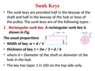
Sunk Keys
• Thesunk keys are provided half in the keyway of the
shaft and half in the keyway of the hub or boss of
the pulley. The sunk keys are of the following types :
1. Rectangular sunk key. A rectangular sunk key is
shown in Fig.
The usual proportions
• Width of key, w = d / 4 ;
• thickness of key, t = 2w / 3 = d / 6
• where d = Diameter of the shaft or diameter of the
hole in the hub.
• The key has taper 1 in 100 on the top side only.
4.
2. Square sunkkey.
• The only difference between a rectangular
sunk key and a square sunk key is that its
width and thickness are equal, i.e.
• w = t = d / 4
3. Parallel sunk key.
• The parallel sunk keys may be of rectangular or
square section uniform in width and thickness
throughout. It may be noted that a parallel key is
a taperless and is used where the pulley, gear or
other mating piece is required to slide along the
shaft.
5.
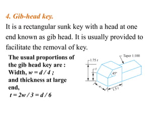
4. Gib-head key.
Itis a rectangular sunk key with a head at one
end known as gib head. It is usually provided to
facilitate the removal of key.
The usual proportions of
the gib head key are :
Width, w = d / 4 ;
and thickness at large
end,
t = 2w / 3 = d / 6
6.
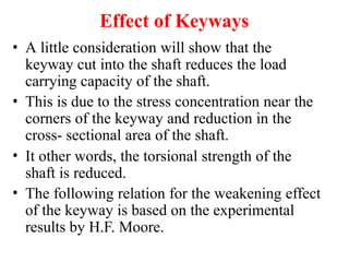
Effect of Keyways
•A little consideration will show that the
keyway cut into the shaft reduces the load
carrying capacity of the shaft.
• This is due to the stress concentration near the
corners of the keyway and reduction in the
cross- sectional area of the shaft.
• It other words, the torsional strength of the
shaft is reduced.
• The following relation for the weakening effect
of the keyway is based on the experimental
results by H.F. Moore.
7.
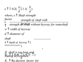
where, e Shaft strength
factor
w h
strength of shaft without keyway for sameshaft
w width of keyway
d diameter of
shaft
h depth of keyway (
thicknessof keyway(t )
)
2
If shaft is too long and
sliding keywaythen
K Re duction factor for
strength of shaft with
keyway
e
h
d d
w
e 1 0.2( ) 1.1( )
o
K 1 0.4( ) 0.7( )
d
8.
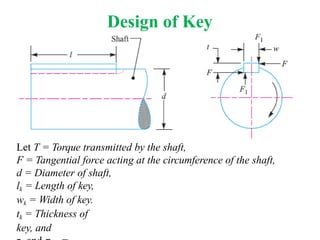
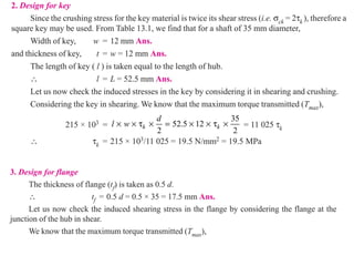
Design of Key
LetT = Torque transmitted by the shaft,
F = Tangential force acting at the circumference of the shaft,
d = Diameter of shaft,
lk = Length of key,
wk = Width of key.
tk = Thickness of
key, and
9.
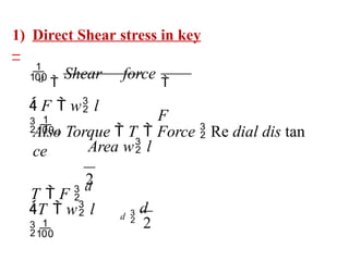
1) Direct Shearstress in key
–
2
2
Also Torque T Force Re dial dis tan
ce
T F
d
d
T w l
Shear force
F
Area w l
F w l
d
d
d
10.
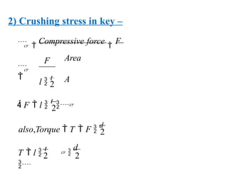
2) Crushing stressin key –
2
2
2
also,Torque T F
d
2
2
d
l
t
F
Compressive force
F
Area
A
cr
T l
t
cr
F l
t
cr
cr
11.
Couplings
• Shafts areavailable in varying length from 6
to 10 meters for easy handling and
transportation.
• Larger length shafts can not be manufactured
in correct for the use of power transmission.
• But in actual practice, larger length shafts are
required for transmission of torque and
power.
• This requirement will be fulfilled by the use
of coupling which joined two or more shafts
so coupling is a device used to join two or
12.
Requirements of aGood Shaft Coupling
• A good shaft coupling should have
the following requirements :
1. It should be easy to connect or
disconnect.
2. It should transmit the full power from one
shaft to the other shaft without losses.
3. It should hold the shafts in perfect alignment.
4. It should reduce the transmission of shock
loads from one shaft to another shaft.
5. It should have no projecting parts.
13.
Factors Consider inSelection of
Coupling
1) Torque requirement.
2) Speed involved.
3) Shaft misalignment.
4) Operating condition.
5) Cyclic operation.
6) Direction of rotation.
7) Life of coupling.
8) Duty or work involved.
14.
• Why acoupling should be placed as close to
a bearing as possible?
Answer – Coupling should be placed as close to
a bearing because of following reasons
1. It gives minimum vibrations.
2. Bending load on the shaft can be minimized.
3. It increases power transmission stability.
4. To avoid deflections of shaft.
15.
Types of Couplings
1)Rigid coupling –
it is used to connect two shafts which are
parallel and in alignment.
a) Sleeve or muff coupling.
b) Clamp or split muff coupling.
c) Flange coupling.
16.
2) Flexible coupling–
It is used to connect two shafts which
are parallel and not in alignment.
a) Bushed pin type flexible coupling.
b) Universal coupling.
c) Oldham coupling.
17.
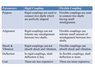
Parameters Rigid CouplingFlexible Coupling
Purpose Rigid couplings are used to
connect two shafts which
are perfectly aligned.
Flexible couplings are used
to connect two shafts
having small
misalignment.
Alignment Rigid couplings can not
tolerate any misalignment
between two shafts.
Flexible couplings can
tolerate small amount of
misalignment between two
shafts.
Shock &
Vibration
Rigid couplings can not
absorb shock and vibration.
Flexible couplings can
absorb shock and vibration.
Deflection In rigid couplings, shaft
deflection is less.
In flexible couplings, shaft
deflection is more.
Cost These are less expensive These are more expensive.
18.
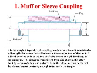
1. Muff orSleeve Coupling
It is the simplest type of rigid coupling, made of cast iron. It consists of a
hollow cylinder whose inner diameter is the same as that of the shaft. It
is fitted over the ends of the two shafts by means of a gib head key, as
shown in Fig. The power is transmitted from one shaft to the other
shaft by means of a key and a sleeve. It is, therefore, necessary that all
the elements must be strong enough to transmit the torque.
19.
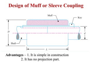
Design of Muffor Sleeve Coupling
Advantages – 1. It is simple in construction
2. It has no projection part.
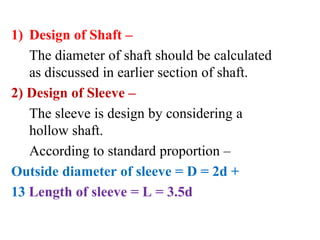
1) Design ofShaft –
The diameter of shaft should be calculated
as discussed in earlier section of shaft.
2) Design of Sleeve –
The sleeve is design by considering a
hollow shaft.
According to standard proportion –
Outside diameter of sleeve = D = 2d +
13 Length of sleeve = L = 3.5d
22.
This equation isused to check
the shear stress in sleeve
D
16
Where k
d
T
D3
(1 k
4
)
3) Considering the torsional
shear failure of sleeve
23.
crushing
d
tk
shearing
d
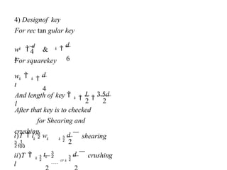
After that key is to checked
for Shearing and
crushing
L
3.5d
d
4
For squarekey
d
6
For rec tan gular key
4) Designof key
cr k
k
ii)T
l
k
k
k
i)T l w
k
And length of key
l
k
k
w
t
k
k
w
d
&
t
2
2 2
4
24.
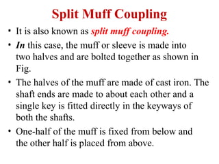
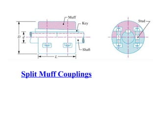
Split Muff Coupling
•It is also known as split muff coupling.
• In this case, the muff or sleeve is made into
two halves and are bolted together as shown in
Fig.
• The halves of the muff are made of cast iron. The
shaft ends are made to about each other and a
single key is fitted directly in the keyways of
both the shafts.
• One-half of the muff is fixed from below and
the other half is placed from above.
25.
• Both thehalves are held together by means
of mild steel studs or bolts and nuts.
• The number of bolts may be two, four or six.
• The nuts are recessed into the bodies of the
muff castings.
• This coupling may be used for heavy duty
and moderate speeds.
• The advantage of this coupling is that the
position of the shafts need not be changed for
assembling or disassembling of the couplings.
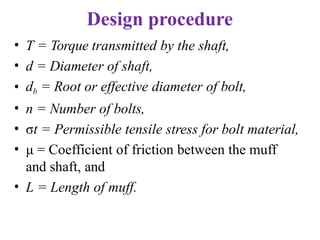
Design procedure
• T= Torque transmitted by the shaft,
• d = Diameter of shaft,
• db = Root or effective diameter of bolt,
• n = Number of bolts,
• σt = Permissible tensile stress for bolt material,
• μ = Coefficient of friction between the muff
and shaft, and
• L = Length of muff.
28.
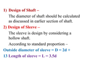
1) Design ofShaft –
The diameter of shaft should be calculated
as discussed in earlier section of shaft.
2) Design of Sleeve –
The sleeve is design by considering a
hollow shaft.
According to standard proportion –
Outside diameter of sleeve = D = 2d +
13 Length of sleeve = L = 3.5d
29.
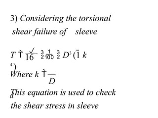
This equation isused to check
the shear stress in sleeve
D
16
Where k
d
T
D3
(1 k
4
)
3) Considering the torsional
shear failure of sleeve
30.
crushing
d
tk
shearing
d
After that key is to checked
for Shearing and
crushing
L
3.5d
d
4
For squarekey
d
6
For rec tan gular key
4) Designof key
cr k
k
ii)T
l
k
k
k
i)T l w
k
And length of key
l
k
k
w
t
k
k
w
d
&
t
2
2 2
4
31.
4
4
2
2
2
b
n
f
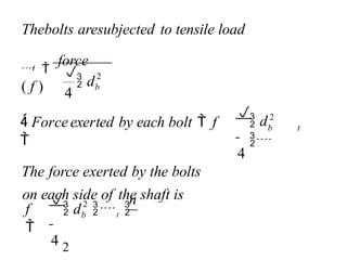
Forceexerted byeach bolt f
The force exerted by the bolts
on each side of the shaft is
4
d
Thebolts aresubjected to tensile load
b
d t
2
t
b
d
t
force
( f )
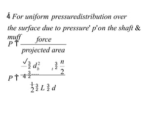
32.
n
projected area
force
P
thesurface due to pressure' p'on the shaft &
muff
For uniform pressuredistribution over
b t
2
1
L d
2
P 4
2
d
33.
n
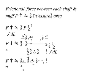
Frictional force betweeneach shaft &
muff F Pr essure area
b
b t
d
2
2
F d t
n
2
2
2
1
dL
F
4
2
1
L
d
2
F P
1
dL
34.
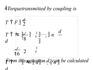
16
2
2
d
From this equationdb can be calculated
.
Torquetransmitted by coupling is
b
2
b t
T F
d
8
2
T dt n
2
n
2
T
d
35.
Flange Couplings
• Aflange coupling usually applies to a
coupling having two separate cast iron flanges.
• Each flange is mounted on the shaft end
and keyed to it.
• The faces are turned up at right angle to the
axis of the shaft.
• One of the flange has a projected portion and the
other flange has a corresponding recess. This
helps to bring the shafts into line and to
maintain alignment.
36.
• The twoflanges are coupled together by means of
bolts and nuts. The flange coupling is adopted to
heavy loads and hence it is used on large
shafting.
• The flange couplings are of the following
three types :
1) Unprotected type flange coupling
2) Protected type flange coupling
3) Marine type flange coupling
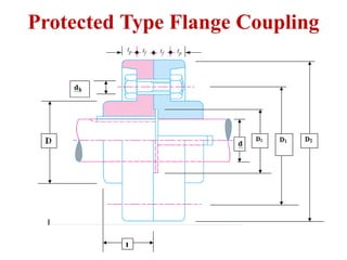
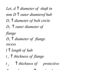
Let, d diameter of shaft in
mm D outer diamterof hub
D1 diameter of bolt circle
D2 outer diameter of
flange
D3 diameter of flange
recess
l length of hub
t f thickness of flange
t p thickness of protective
40.
• The designof rigid flange coupling can be
done in two different ways, depending upon
the fit of the bolts in flange holes.
• If bolts are fitted in reamed holes and are finger-
tight, in such case, the torque is transmitted by
the shear resistance and crushing resistance of
the bolts.
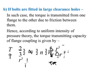
• If the bolts are fitted in large clearance holes and
are tightened sufficiently with pre-load, in such
case, the torque is transmitted from one flange
to the other not through the bolts but due to
friction between the two flanges.
41.
1. Design ofShaft & Key
– The shaft and keys are designed
as discussed in earlier sections.
42.
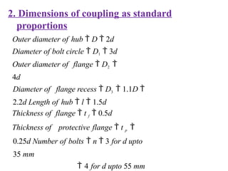
2. Dimensions ofcoupling as standard
proportions
Outer diameter of hub D 2d
Diameter of bolt circle D1 3d
Outer diameter of flange D2
4d
Diameter of flange recess D3 1.1D
2.2d Length of hub l 1.5d
Thickness of flange t f 0.5d
Thickness of protective flange t p
0.25d Number of bolts n 3 for d upto
35 mm
4 for d upto 55 mm
43.
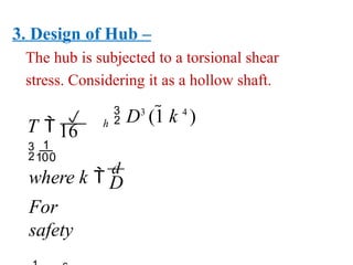
3. Design ofHub –
The hub is subjected to a torsional shear
stress. Considering it as a hollow shaft.
For
safety
h
D
where k
d
D3
(1 k 4
)
T
16
44.
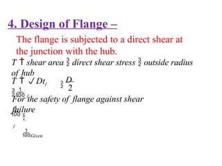
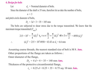
4. Design ofFlange –
The flange is subjected to a direct shear at
the junction with the hub.
T shear area direct shear stress outside radius
of hub
Given
f
T Dtf
f
For the safety of flange against shear
failure
D
2
45.
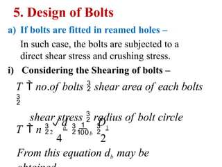
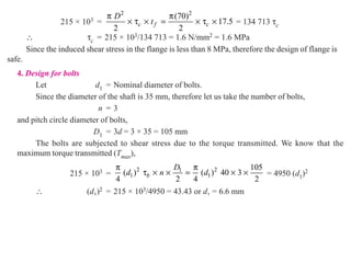
5. Design ofBolts
a) If bolts are fitted in reamed holes –
In such case, the bolts are subjected to a
direct shear stress and crushing stress.
i) Considering the Shearing of bolts –
T no.of bolts shear area of each bolts
shear stress radius of bolt circle
From this equation db may be
D
4 2
T n b
b 1
d
2
46.
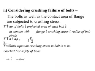
ii) Considering crushingfailure of bolts –
The bolts as well as the contact area of flange
are subjected to crushing stress.
D1
2
Fromthis equation crushing stress in bolt is to be
checked For safety of bolts
crb cr (Given )
T no.of bolts projected area of each bolt
in contact with flange crushing stress radius of bolt
circle
T n dbt f
crb
47.
b) If boltsare fitted in large clearance holes –
In such case, the torque is transmitted from one
flange to the other due to friction between
them.
Hence, according to uniform intensity of
pressure theory, the torque transmitting capacity
of flange coupling is given by –
o i
r 2
r 2
2 r3
r3
n W
o i
T
3
48.
2
3
2
2
D
D
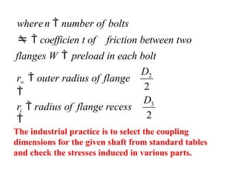
ro outerradius of flange
wheren number of bolts
coefficien t of friction between two
flanges W preload in each bolt
i
r radius of flange recess
The industrial practice is to select the coupling
dimensions for the given shaft from standard tables
and check the stresses induced in various parts.
54.
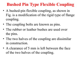
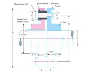
Bushed Pin TypeFlexible Coupling
• A bushed-pin flexible coupling, as shown in
Fig. is a modification of the rigid type of flange
coupling.
• The coupling bolts are known as pins.
• The rubber or leather bushes are used over
the pins.
• The two halves of the coupling are dissimilar
in construction.
• A clearance of 5 mm is left between the face
of the two halves of the coupling.
55.
• There isno rigid connection between them and
the drive takes place through the medium of
the compressible rubber or leather bushes.
• In designing the bushed-pin flexible coupling,
the proportions of the rigid type flange coupling
are modified.
• The main modification is to reduce the
bearing pressure on the rubber or leather
bushes and it should not exceed 0.5 N/mm2.
• In order to keep the low bearing pressure, the
pitch circle diameter and the pin size is
increased.
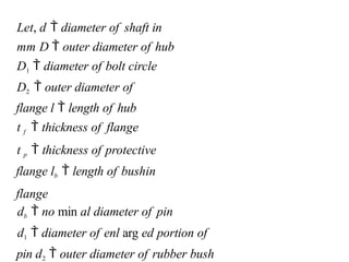
Let, d diameter of shaft in
mm D outer diameter of hub
D1 diameter of bolt circle
D2 outer diameter of
flange l length of hub
t f thickness of flange
t p thickness of protective
flange lb length of bushin
flange
db no min al diameter of pin
d1 diameter of enl arg ed portion of
pin d2 outer diameter of rubber bush
59.
1. Design ofshaft and key
–
The shaft and key are designed as discussed
in earlier sections.
2. Dimensions of coupling as standard
proportions –
outer diameter of hub D 2d
length of hub l 1.5d
Thickness of flange t f
0.5d
Thickness of protective flange t p
0.25d Number of pins n 3 for d upto
30 mm
4 for d upto 75 mm
6 for d upto110 mm
60.
3. Design ofhub –
The hub is subjected to a torsional shear
stress.
Considering it as hollow shaft.
D3
(1 k 4
)
h
16
Where, h torsional shear stress
in hub For safety of hub
h (Given )
Then the design of hub is safe
T
61.
4. Design ofFlange –
The flange is subjected to a direct shear stress
at the junction of the hub.
T shear area direct shear stress outside radius of
hub
Thenthe design of flange is
safe.
2
(Given )
For safety of flange against
shear
D
T n Dt f
f
f
62.
5. Design ofpins –
A) Calculate the dimensions of pin
i) Select the number of pins (n)
ii) Nominal diameter of pin
d
0.5 d
n
b
The standard nominal diameter is selected.
63.
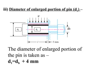
iii) Diameter ofenlarged portion of pin (d1) –
The diameter of enlarged portion of
the pin is taken as –
d1=db + 4 mm
64.
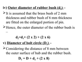
iv) Outer diameterof rubber bush (d2) –
It is assumed that the brass bush of 2 mm
thickness and rubber bush of 6 mm thickness
are fitted on the enlarged portion of pin.
Hence, the outer diameter of the rubber bush is
–
d2=d1+ (2 x 2) + (2 x 6)
v) Diameter of bolt circle (D1) –
Considering the distance of 8 mm between
the outer surface of hub and the rubber bush.
D1 = D + d2 + (2 x 8)
65.
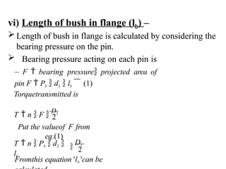
vi) Length ofbush in flange (lb) –
Length of bush in flange is calculated by considering the
bearing pressure on the pin.
Bearing pressure acting on each pin is
– F bearing pressure projected area of
pin F Pb d2 lb (1)
Fromthis equation 'lb 'can be
D1
T n Pb d2
lb
2
Put the valueof F from
eq.(1)
Torquetransmitted is
T n F
D1
2
66.
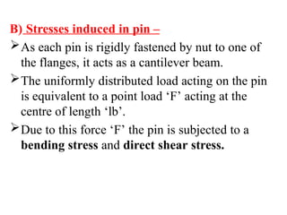
B) Stresses inducedin pin –
As each pin is rigidly fastened by nut to one of
the flanges, it acts as a cantilever beam.
The uniformly distributed load acting on the pin
is equivalent to a point load ‘F’ acting at the
centre of length ‘lb’.
Due to this force ‘F’ the pin is subjected to a
bending stress and direct shear stress.
67.
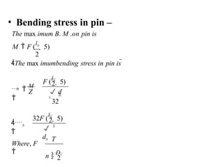
• Bending stressin pin –
The max imum B. M .on pin is
M F (
lb
5)
2
The max imumbending stress in pin is
2
Where, F
2
2
b
32
F (
lb
5)
n
D1
3
32F (
lb
5)
d
3
T
db
Z
b
b
M
68.
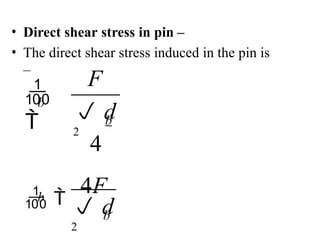
• Direct shearstress in pin –
• The direct shear stress induced in the pin is
–
b
4
d
2
4F
b
d
2
b
b
F
69.
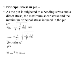
• Principal stressin pin –
• As the pin is subjected to a bending stress and a
direct stress, the maximum shear stress and the
maximum principal stress induced in the pin
are
max
max
2 2
2
b
2
b
2
2
b
2
b
b
and
for safety of
pin
max (Given )
(
(
70.
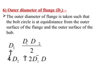
6) Outer diameterof flange (D2) –
The outer diameter of flange is taken such that
the bolt circle is at equidistance from the outer
surface of the flange and the outer surface of the
hub.
D2 2D1 D
D D
D
2
1
2
71.
Design of SpurGears
• Gears are defined as toothed wheels or
multilobed cams which are used to transmit
power and motion from one shaft to another
shaft when the distance between the two shaft is
small.
• It is called as positive drive and the velocity
ratio remains constant.
• The gears are transmit large power and
are compact in construction.
• Also they are able to transmit the motion at
very low speed.
72.
Design Considerations fora Gear Drive
• The power to be transmitted.
• The velocity ratio or speed of the gear drive.
• The central distance between the two shaft.
• Input speed of the driving gear.
• The strength of gear teeth so that they will not fail
under static loading or dynamic loading under
normal running condition.
• Wear characteristics of the gear tooth for a long
satisfactory life.
• The use of space and material and cost should be
economical.
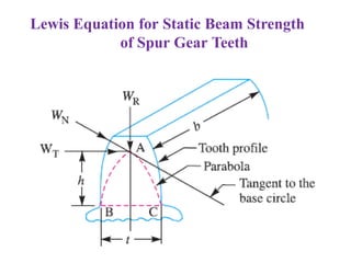
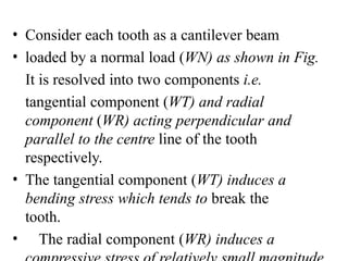
• Consider eachtooth as a cantilever beam
• loaded by a normal load (WN) as shown in Fig.
It is resolved into two components i.e.
tangential component (WT) and radial
component (WR) acting perpendicular and
parallel to the centre line of the tooth
respectively.
• The tangential component (WT) induces a
bending stress which tends to break the
tooth.
• The radial component (WR) induces a
75.
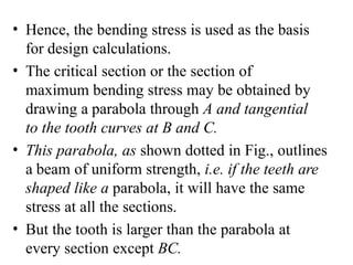
• Hence, thebending stress is used as the basis
for design calculations.
• The critical section or the section of
maximum bending stress may be obtained by
drawing a parabola through A and tangential
to the tooth curves at B and C.
• This parabola, as shown dotted in Fig., outlines
a beam of uniform strength, i.e. if the teeth are
shaped like a parabola, it will have the same
stress at all the sections.
• But the tooth is larger than the parabola at
every section except BC.
76.
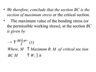
• We therefore,conclude that the section BC is the
section of maximum stress or the critical section.
• The maximum value of the bending stress (or
the permissible working stress), at the section BC
is given by
I
b
Where, M Maximum B. M .of critical sec tion
BC M WT h
M y
(1)
77.
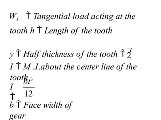
b Facewidth of
gear
bt3
I
WT Tangential load acting at the
tooth h Length of the tooth
y Half thickness of the tooth
t
2
I M .I.about the center line of the
tooth
12
78.
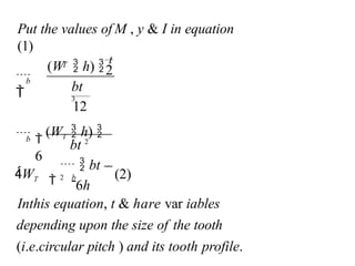
Inthis equation, t& hare var iables
depending upon the size of the tooth
(i.e.circular pitch ) and its tooth profile.
(2)
6h
12
(WT h)
6
2
Put the values of M , y & I in equation
(1)
bt 2
bt
3
WT b
bt
2
b
T
(W h)
t
b
79.
WT b b Pc y
WT b b M
6k
x2
Put y
WT b b c
6kP
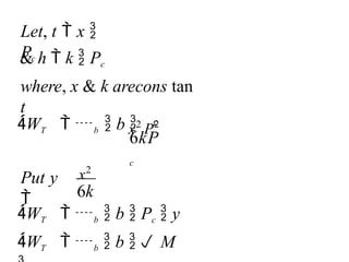
c
Let, t x
Pc
& h k Pc
where, x & k arecons tan
t
x2
P2
80.
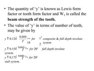
• The quantityof ‘y’ is known as Lewis form
factor or tooth form factor and WT is called the
beam strength of the tooth.
• The value of ‘y’ in terms of number of teeth,
may be given by
composite & full depth involute
system
10
2
for
14
0.684
y 0.124
T
T
y 0.175
0.841
for 200
stub system.
y 0.154
0.912
for 200
full depth involute
system.
T
81.
Permissible Working stress(Bending stress) for Gear
Teeth in the Lewis equation
• The permissible working stress in the Lewis
equation depends upon the material for which
an allowable static stress may be determined.
• The allowable static stress is the stress at
the elastic limit of the material.
• It is also called as basic stress.
82.
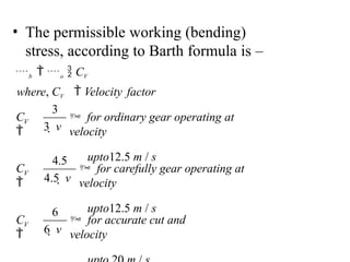
• The permissibleworking (bending)
stress, according to Barth formula is –
b o CV
where, CV Velocity factor
for accurate cut and
velocity
6 v
for carefully gear operating at
velocity
upto12.5 m / s
4.5 v
for ordinary gear operating at
velocity
upto12.5 m / s
3 v
V
C
V
C
V
C
6
4.5
3
83.
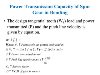
Power Transmission Capacityof Spur
Gear in Bending
• The design tangential tooth (WT) load and power
transmitted (P) and the pitch line velocity is
given by equation.
V
T S
W
P
C
Where,WT Permissible tan gential tooth load in
N WT b b m y ( oCV )b m y
P Power transmitted in watt
V Pitch line velocity in m / s
DN
60
CS Service factor
D P.C.D.of gear in meters
84.
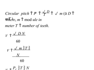
T
C
where, m mod ule in
meter T number of teeth.
V
D N
60
V
m T
N
60
P T N
Circular pitch P
D
m ( D
mT )
85.
Modes / Causesof Gear tooth Failure
1. Bending failure or tooth breakage –
Gear tooth behave like a cantilever beam subjected to a
repetitive bending stress. The tooth may break due to
repetitive bending stress.
The tooth breakage occurs when the repetitive bending
stress induced in the gear tooth exceed the bending
endurance strength of the gear tooth.
In other words the tooth breakage occurs when the total
load acting on the gear tooth exceed beam strength of the
gear tooth.
The tooth breakage can be avoided by adjusting the
parameters such as module and face width in the gear design.
86.
2. Wear Failure–
The wear is the phenomenon which removes the
complete layer of the surface or makes craters or
scratches on the surface.
The different types of wear failure in the gear tooth
are discuss below.
a) Pitting –
It is the surface fatigue failure due to
repetitive contact stresses.
The pitting starts when total load acting on the
gear tooth exceeds the wear strength of the
gear tooth.
87.
b) Scoring –
Scoringis essentially a lubrication failure.
In adequate lubrication along with the high
tooth load and poor surface finish result in
breakdown of the oil film and cause the metal to
metal contact.
This causes rapid alteration welding and
tearing at high spots which is known as stick-
slip phenomenon.
88.
c) Abrasive Wear
–
Abrasivewear is a surface damage caused by
particles trapped in between the meeting teeth
surfaces.
These particles may be present in lubricant as
impurities, may be the dirt entering the gearbox from
outside or may be flakes of material detached from
the tooth surface.
Abrasive wear may be minimize by proper filtration
of the lubricant, providing complete enclosure for
gear, increasing the surface hardness and use of high
viscosity oils.
89.
d) Corrosive Wear–
The corrosive wear is due to chemical action by
the improper lubricant or sometime it may be
due to surrounding atmosphere which may be
corrosive in nature.
The remedies against corrosive wear are
using proper lubricant with proper additives
and providing complete enclosure for gears.