RAJASTHAN TECHNICAL UNIVERSITYKOTA
BTECH 3rd YEAR 5th SEMESTER
BRANCH : MECHANICAL ENGINEERING
SUBJECT : MDP LAB
BATCH : M3
TITLE : DESIGN OF COUPLING ( MUFF & FLANGE )
SUBMITTED BY :
SUBMITTED BY:
R.K BHAMU SIR
Ayush Pal
Rohit Verma
24/910
24/946
Satyam 24/951
Atul Kumawat
Jayesh Jangid
24/909
24/924
2.
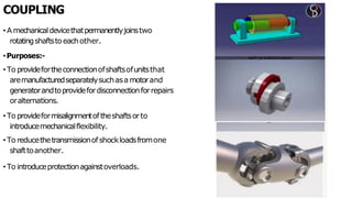
COUPLING
• A mechanicaldevicethatpermanentlyjoinstwo
rotatingshaftstoeachother.
•Purposes:-
•To providefortheconnectionofshaftsofunitsthat
aremanufacturedseparatelysuchasa motorand
generatorandtoprovidefordisconnectionforrepairs
oralternations.
• To provideformisalignmentoftheshaftsorto
introducemechanicalflexibility.
• To reducethetransmissionofshockloadsfromone
shafttoanother.
• To introduceprotectionagainstoverloads.
3.
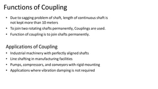
Functions of Coupling
•Due to sagging problem of shaft, length of continuous shaft is
not kept more than 10 meters
• To join two rotating shafts permanently, Couplings are used.
• Function of coupling is to join shafts permanently.
Applications of Coupling
• Industrial machinery with perfectly aligned shafts
• Line shafting in manufacturing facilities
• Pumps, compressors, and conveyors with rigid mounting
• Applications where vibration damping is not required
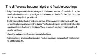
A good coupling,rigidorflexible,shouldsatisfy the
following requirements:
1
1
/
1
1/
20
2
5 7
• Thecouplingshouldbecapableoftransmittingtorquefromthedrivingshafttothe
drivenshaft.
• Thecouplingshouldkeepthetwoshaftsinproperalignment.
• Thecouplingshouldbeeasytoassembleanddisassembleforthepurposeofrepairs
andalterations.
• Thefailureofrevolvingboltheads,nuts,keyheadsandotherprojectingpartsmay
causeaccidents.Theyshouldbecoveredbygivingsuitableshapetotheflangesorby
providingguards.
8.
3/17/2021 Vijay KumarKarma, IET, DAVV, Indore 5
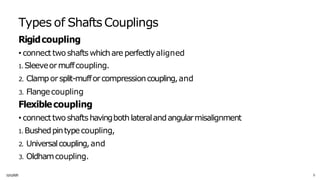
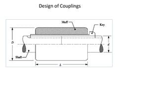
Design of Couplings
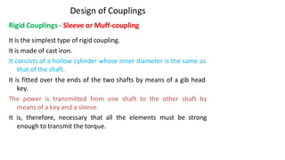
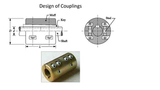
Rigid Couplings - Sleeve or Muff-coupling
It is the simplest type of rigid coupling.
It is made of cast iron.
It consists of a hollow cylinder whose inner diameter is the same as
that of the shaft.
It is fitted over the ends of the two shafts by means of a gib head
key.
The power is transmitted from one shaft to the other shaft by
means of a key and a sleeve.
It is, therefore, necessary that all the elements must be strong
enough to transmit the torque.
Design of Couplings
4
3/17/2021Vijay Kumar Karma, IET, DAVV, Indore 7
3
16
16 D
c 1− k
D4
= D ( )
− d4
T = c
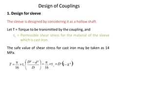
1. Design for sleeve
The sleeve is designed by considering it as a hollow shaft.
Let T = Torque to be transmitted by the coupling, and
τc = Permissible shear stress for the material of the sleeve
which is cast iron.
The safe value of shear stress for cast iron may be taken as 14
MPa.
11.
Design of Couplings
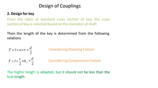
2.Design for key
From the table of standard cross section of key, the cross
section of key is selected based on the diameter of shaft.
Then the length of the key is determined from the following
relations
Considering Shearing Failure
Considering Compression Failure
2
T = l w
d
d
2
Vijay Kumar Karma, IET, DAVV, Indore 8
2
c
T = l
t
12.
Design of Couplings
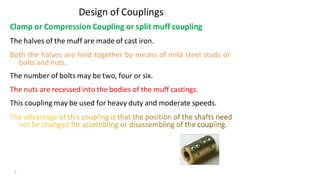
Clampor Compression Coupling or split muff coupling
The halves of the muff are made of cast iron.
Both the halves are held together by means of mild steel studs or
bolts and nuts.
The number of bolts may be two, four or six.
The nuts are recessed into the bodies of the muff castings.
This coupling may be used for heavy duty and moderate speeds.
3/17/2021 Vijay Kumar Karma, IET, DAVV, Indore 9
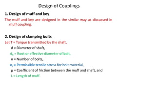
Design of Couplings
1.Design of muff and key
The muff and key are designed in the similar way as discussed in
muff coupling.
2. Design of clamping bolts
Let T = Torque transmitted by the shaft,
d = Diameter of shaft,
db = Root or effective diameter of bolt,
n = Number of bolts,
μ = Coefficient of friction between the muff and shaft, and
L = Length of muff.
3/17/2021 Vijay Kumar Karma, IET, DAVV, Indore 11
15.
Design of Couplings
Forceexerted by each bolt F =
∴ Force exerted by the bolts on each side of the shaft
Let p be the pressure on the shaft and the muff surface due to the
force, then for uniform pressure distribution over the surface,
t
b
(d )
4
2
n
Pr ojected Area
F
p =
b t
2
1
L d
2
= 4
2
(d )
n
2
3/17/2021 Vijay Kumar Karma, IET, DAVV, Indore 12
4
2
1
F = b t
(d )
16.
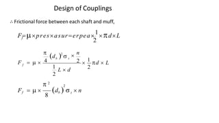
Design of Couplings
∴Frictional force between each shaft and muff,
f
2
F=presasur=erpea
1
dL
(d ) n
b t
f
2
2
1
d L
F = 4
2
1
L d
2
t
Vijay Kumar Karma, IET, DAVV, Indore 13
2
2
Ff = (db ) n
8
17.
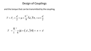
Design of Couplings
andthe torque that can be transmitted by the coupling,
)2 d
d 2
(
T = Ff
2
=
8
db t n
2
t
3/17/2021 Vijay Kumar Karma, IET, DAVV, Indore 14
n d
T = ( d b )
2
2
1 6
18.
Design of Couplings
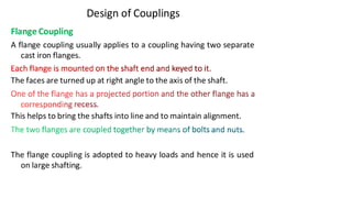
FlangeCoupling
A flange coupling usually applies to a coupling having two separate
cast iron flanges.
The faces are turned up at right angle to the axis of the shaft.
This helps to bring the shafts into line and to maintain alignment.
The flange coupling is adopted to heavy loads and hence it is used
on large shafting.
3/17/2021 Vijay Kumar Karma, IET, DAVV, Indore 15
19.
Design of Couplings
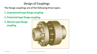
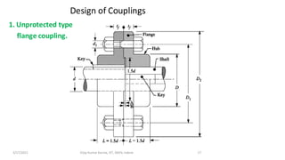
Theflange couplings are of the following three types :
1. Unprotected type flange coupling.
2. Protected type flange coupling.
3. Marine type flange
coupling.
3/17/2021 Vijay Kumar Karma, IET, DAVV, Indore 16
Design of Couplings
coupling.
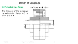
2.Protected type flange
The thickness of the protective
circumferential flange (tp) is
taken as 0.25 d.
3/17/2021 Vijay Kumar Karma, IET, DAVV, Indore 18
22.
Design of Couplings
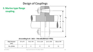
3.Marine type flange
coupling.
3/17/2021 Vijay Kumar Karma, IET, DAVV, Indore 19
23.
3/17/2021 Vijay KumarKarma, IET, DAVV, Indore 20
Design of Couplings
Design of Flange Coupling
Consider a flange coupling as shown in Figure above.
Let
τs, τb
d = Diameter of shaft or inner diameter of hub,
D = Outer diameter of hub,
d1 = Nominal or outside diameter of bolt,
D1 = Diameter of bolt circle,
n = Number of bolts,
tf = Thickness of flange,
and τk = Allowable shear stress for shaft, bolt and key material
respectively
τc = Allowable shear stress for the flange material i.e. cast iron,
σcb, and σck = Allowable crushing stress for bolt and key material
respectively.
24.
Design of Couplings
1.Design for hub
The hub is designed by considering it as a hollow shaft, transmitting
the same torque (T) as that of a solid shaft.
2. Design for key
The key is designed with usual proportions and then checked for
shearing and crushing stresses.
The material of key is usually the same as that of shaft. The length
of key is taken equal to the length of hub
16
3/17/2021 Vijay Kumar Karma, IET, DAVV, Indore 21
16 D
c
D4
= D3
(1−k4
)
− d4
T = c
25.
Design of Couplings
3.Design for flange
The flange at the junction of the hub is under shear while
transmitting the torque.
Therefore, the torque transmitted,
T = Circumference of hub × Thickness of flange × Shear stress of
flange × Radius of hub
The thickness of flange is usually taken as half the diameter of shaft.
c tf
3/17/2021 Vijay Kumar Karma, IET, DAVV, Indore 22
T = Dtf c
2
=
D D2
2
26.
Design of Couplings
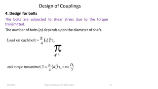
4.Design for bolts
The bolts are subjected to shear stress due to the torque
transmitted.
The number of bolts (n) depends upon the diameter of shaft.
(d ) b
Load on eachbolt =
4
2
1
2
and torque transmitted,T =
2
1 b
(d ) n
D1
4
3/17/2021 Vijay Kumar Karma, IET, DAVV, Indore 23
41 b
T
L
o
o
a
o
b
t
n
l
=
t
h
(
d
a
l
)
o
a
2
27.
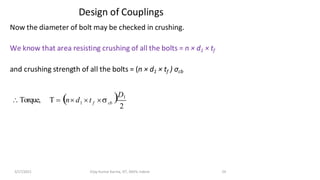
Design of Couplings
Nowthe diameter of bolt may be checked in crushing.
We know that area resisting crushing of all the bolts = n × d1 × tf
and crushing strength of all the bolts = (n × d1 × tf ) σcb
T = (n d
2
3/17/2021 Vijay Kumar Karma, IET, DAVV, Indore 24
)D1
Torque, 1 cb
f
t